Table of Contents
Advertisement
Quick Links
One Technology Way • P.O. Box 9106 • Norwood, MA 02062-9106, U.S.A. • Tel: 781.329.4700 • Fax: 781.461.3113 • www.analog.com
Full-featured evaluation board for the AD7276
PC control in conjunction with the System Demonstration
Platform (EVAL-SDP-CB1Z)
PC software for control and data analysis (time and
frequency domain)
Standalone capability
EVAL-AD7276SDZ KIT CONTENTS
EVAL-AD7276SDZ Evaluation Board
Evaluation Software CD for the AD7276
9V Mains power supply adapter
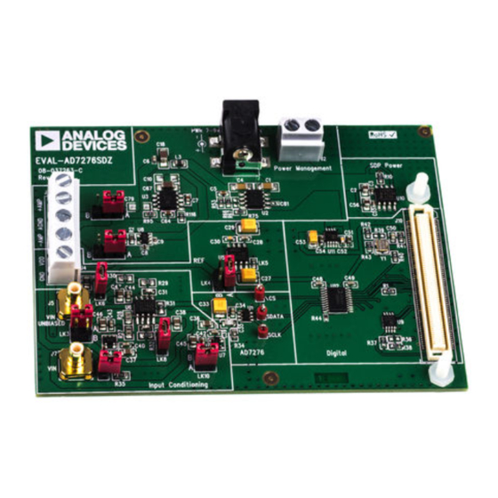
EVALUATION BOARD DESCRIPTION
The EVAL-AD7276SDZ is a full-featured evaluation board,
designed to allow the user to easily evaluate all features of the
AD7276. The evaluation board can be controlled via the system
demonstration platform (SDP) connector (J8). The EVAL-SDP-
CB1Z board allows the evaluation board to be controlled via the
USB port of a PC using the AD7276 evaluation software.
The EVAL-AD7276SDZ generates all required power supplies
on board and supplies power to the EVAL-SDP-CB1Z controller
board.
On-board components include the:
•
AD8022: Dual High Speed, Low Noise Op Amp
•
ADA4000-1: Single, Low Cost, Precision JFET Input
Operational Amplifier
PLEASE SEE THE LAST PAGE FOR AN IMPORTANT
WARNING AND LEGAL TERMS AND CONDITIONS.
Evaluation Board User Guide
Evaluating the AD7276
ADDITIONAL EQUIPMENT NEEDED
System Demonstration platform (EVAL-SDP-CB1Z)
Precision Analog signal source
SMB cables
USB Cables
Various link options are described in the Evaluation Board
Hardware section.
Rev. PrA | Page 1 of 28
•
AD780: 2.5 V/3.0 V Ultrahigh Precision Bandgap
Voltage Reference
•
ADP1613: Step-Up PWM DC-to-DC Switching
Converter,
•
ADP1720: 50 mA, High Voltage, Micropower Linear
Regulator
•
ADP7104: 20 V, 500 mA, Low Noise, CMOS LDO
ADM1185: Quad Voltage Monitor and Sequencer
•
ADG3308: Low Voltage, 1.15 V to 5.5 V, 8-Channel
Bidirectional Logic Level Translator
UG-xxx-AD7276
Advertisement
Table of Contents

Subscribe to Our Youtube Channel
Related Manuals for Analog Devices EVAL-AD7276SDZ


Summary of Contents for Analog Devices EVAL-AD7276SDZ
-
Page 1: Eval-Ad7276Sdz Kit Contents
Evaluation Software CD for the AD7276 9V Mains power supply adapter EVALUATION BOARD DESCRIPTION The EVAL-AD7276SDZ is a full-featured evaluation board, • AD780: 2.5 V/3.0 V Ultrahigh Precision Bandgap designed to allow the user to easily evaluate all features of the Voltage Reference AD7276. -
Page 2: Functional Block Diagram
SHIFTER ADA4000-1 BUFFER EVAL-SDP-CB1Z BIAS UP CIRCUIT CONTROLLER VIN Unbiased EVAL-AD7276SDZ BOARD 48MHZ SCLK AD8022 Figure 1 Functional Block Diagram PLEASE SEE THE LAST PAGE FOR AN IMPORTANT Rev. PrA | Page 2 of 28 WARNING AND LEGAL TERMS AND CONDITIONS. -
Page 3: Table Of Contents
TABLE OF CONTENTS EVAL-AD7276SDZ KIT Contents ..........1 Sockets/Connectors ..............9 Additional Equipment Needed ............1 EVAL-AD7276SDZ Basic Hardware Setup ......10 Evaluation Board Description ............1 Evaluation Board SoftwarE ............11 Functional Block Diagram ............... 2 Software Installation ..............11 Revision History ................ -
Page 4: Eval-Ad7276Sdz Quickstart Guide
Analog Devices subfolder in the Programs menu. (4) Screwing the two boards together with the enclosed nylon screw-nut set will ensure the boards connect firmly together. Figure 2. Hardware Configuration – Setting up the EVAL-AD7276SDZ. Rev. PrA | Page 4 of 28... -
Page 5: Evaluation Board Hardware
Evaluation Board User UG-xxx-AD7276 Guide EVALUATION BOARD HARDWARE AD7276 DEVICE DESCRIPTION The AD7276/AD7277/AD7278 are 12-/10-/8-bit, high speed, low power, successive approximation analog-to-digital converters (ADCs), respectively. The parts operate from a single 2.35 V to 3.6 V power supply and feature throughput rates of up to 3 MSPS. -
Page 6: Hardware Link Options
Evaluation Board User UG-xxx-AD7276 Guide HARDWARE LINK OPTIONS There are 12 link options, which must be set for the required operating setup before using the evaluation board. The functions of these options are outlined in Table 1. Shows the position in which all the links are set when the evaluation board is packaged. Jumper and solder link (LKx) options must be set correctly to select the appropriate operating setup before using the evaluation board. - Page 7 Evaluation Board User UG-xxx-AD7276 Guide Table 2 Link Options -Setup condition Link No. Position Function Amplifier negative voltage supplied from on board supply Amplifier Positive voltage supplied from on board supply Selected voltage level is VDD to U4-A VDD sourced from U5 INSERTED U5 output voltage is 3.0V INSERTED...
-
Page 8: Power Supplies
STAND-ALONE MODE Care should be taken before applying power and signals to the The EVAL-AD7276SDZ may also be used without the EVAL- evaluation board to ensure that all link positions are as required SDP-CB1Z. In this case, connection to the digital interface in by the operating mode. -
Page 9: Reference Options
Evaluation Board User UG-xxx-AD7276 Guide REFERENCE OPTIONS SOCKETS/CONNECTORS the reference source is an AD780: 2.5 V/3.0 V Ultrahigh Table 7 Socket connector functions Precision Bandgap Voltage Reference. The reference is taken from Socket Function the VDD pin of the AD7276. An external VDD voltage may also J1 PWR 7- 9V DC transformer power connector. -
Page 10: Eval-Ad7276Sdz Basic Hardware Setup
Evaluation Board User UG-xxx-AD7276 Guide may be used to power the EVAL-AD7276SDZ via J2. Further EVAL-AD7276SDZ BASIC HARDWARE SETUP details on the required power supplies connections and options The AD7276 evaluation board connects to the (EVAL-SDP- are detailed in Table 7 Socket connector functions CB1Z) System Demonstration Board. -
Page 11: Evaluation Board Software
Evaluation Board User UG-xxx-AD7276 Guide EVALUATION BOARD SOFTWARE SOFTWARE INSTALLATION The EVAL-AD7276SDZ evaluation kit includes software on a CD. Click the setup.exe file from the CD to run the install. The default location for the software is C:\Program Files\Analog Devices\EVAL-AD7276_77_78SDZ Note:... - Page 12 Evaluation Board User UG-xxx-AD7276 Guide Figure 10. ADI EVAL-SDP-CB1Z Drivers Setup Window 3 Figure 7. AD7276 Install Window 5. Figure 11. ADI EVAL-SDP-CB1Z Drivers Setup Window 4 Figure 8. ADI EVAL-SDP-CB1Z Drivers Setup Window 1. Figure 12. ADI EVAL-SDP-CB1Z Drivers Setup Window 5 Figure 9.
-
Page 13: Launching The Software
After installation from CD is complete, connect the EVAL- To launch the software, complete the following steps: AD7276SDZ to the EVAL-SDP-CB1Z as described in the From the Start menu, select Programs ->Analog Devices - Evaluation Board Hardware section. > EVAL-AD7276_77_78SDZ > AD7276. The main window of the software then displays. -
Page 14: Description Of User Software Panel
Evaluation Board User UG-xxx-AD7276 Guide Figure 15. Setup Screen Use this drop down menu to select the generic AD7276, DESCRIPTION OF USER SOFTWARE PANEL AD7277 or AD7278. The user software panel as shown in Figure 15 has the following Resolution of selected part is displayed features: Sampling Rate. - Page 15 Evaluation Board User UG-xxx-AD7276 Guide than the ability of the existing device, the software will indicate this and revert to the max Sample frequency. Select the number of samples to analyze. Exit Button. Use this to exit the software. Alternatively, go “Sample”...
-
Page 16: Waveform Capture
Evaluation Board User UG-xxx-AD7276 Guide Figure 16. Waveform Capture Tab The waveform analysis reports back the amplitudes recorded WAVEFORM CAPTURE from the captured signal in addition to the frequency of the Figure 16 illustrates the waveform capture tab. The input signal signal tone. -
Page 17: Ac Testing - Histogram
Evaluation Board User UG-xxx-AD7276 Guide Figure 17. Histogram Capture Tab Illustrates the different measured values for the data AC TESTING - HISTOGRAM captured. Figure 17 shows the histogram capture tab. This tests the ADC DC TESTING - HISTOGRAM for the code distribution for AC input and computes the mean and standard deviation, or transition noise of the converter and More commonly, the histogram would be used for DC testing. -
Page 18: Ac Testing - Fft Capture
Evaluation Board User UG-xxx-AD7276 Guide Figure 18. FFT Capture Tab band-pass filter when the full-scale input range is more than a AC TESTING - FFT CAPTURE few Vpp, it is recommended to use the on board amplifiers to Figure 18 shows the FFT capture tab This tests the traditional amplify the signal, thus preventing the filter from distorting the AC characteristics of the converter and displays a Fast Fourier input signal. -
Page 19: Summary Tab
Evaluation Board User UG-xxx-AD7276 Guide Figure 19. Summary Tab SUMMARY TAB Figure 19 shows the summary tab The summary tab captures all the display information and provides them in one panel with a synopsis of the information including key performance parameters such as SNR and THD Rev. -
Page 20: Save File
.tsv (tab-separated values). may have to navigate to find these files. The default location for the example files is C:\Program Files\Analog Devices\ EVAL- User will be prompted with a Save dialog box and should save... -
Page 21: Evaluation Board Schematics And Artwork
Evaluation Board User UG-xxx-AD7276 Guide EVALUATION BOARD SCHEMATICS AND ARTWORK Figure 22. Schematic page 1 Rev. PrA | Page 21 of 28... - Page 22 Evaluation Board User UG-xxx-AD7276 Guide Figure 23. Schematic page 2 Rev. PrA | Page 22 of 28...
- Page 23 Evaluation Board User UG-xxx-AD7276 Guide Figure 24. Schematic page 3 Rev. PrA | Page 23 of 28...
- Page 24 Evaluation Board User UG-xxx-AD7276 Guide Figure 25 Schematic page 4 Rev. PrA | Page 24 of 28...
- Page 25 Evaluation Board User UG-xxx-AD7276 Guide Figure 26. Top Printed Circuit Board (PCB) Silkscreen Rev. PrA | Page 25 of 28...
- Page 26 Evaluation Board User UG-xxx-AD7276 Guide Figure 27. Layer 1 Component side view Rev. PrA | Page 26 of 28...
- Page 27 Evaluation Board User UG-xxx-AD7276 Guide Figure 28. Layer 2 Component Side view Rev. PrA | Page 27 of 28...
- Page 28 By using the evaluation board discussed herein (together with any tools, components documentation or support materials, the “Evaluation Board”), you are agreeing to be bound by the terms and conditions set forth below (“Agreement”) unless you have purchased the Evaluation Board, in which case the Analog Devices Standard Terms and Conditions of Sale shall govern. Do not use the Evaluation Board until you have read and agreed to the Agreement.
Need help?
Do you have a question about the EVAL-AD7276SDZ and is the answer not in the manual?
Questions and answers