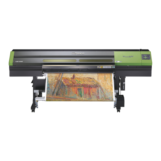
Roland LEC-540 User Manual
Hide thumbs
Also See for LEC-540:
- Setup & maintenance manual (77 pages) ,
- Setup manual (68 pages) ,
- Supplemental manual (34 pages)
Table of Contents
Advertisement
Quick Links
Thank you very much for purchasing this product.
To ensure correct and safe usage with a full understanding of this product's performance, please be sure to read through
this manual completely and store it in a safe location.
Unauthorized copying or transferral, in whole or in part, of this manual is prohibited.
The contents of this operation manual and the specifications of this product are subject to change without notice.
The operation manual and the product have been prepared and tested as much as possible. If you find any misprint or
error, please inform us.
Roland DG Corp. assumes no responsibility for any direct or indirect loss or damage which may occur through use of this
product, regardless of any failure to perform on the part of this product.
Roland DG Corp. assumes no responsibility for any direct or indirect loss or damage which may occur with respect to
any article made using this product.
User's Manual
Advertisement
Table of Contents

Related Manuals for Roland LEC-540


Summary of Contents for Roland LEC-540
- Page 1 The operation manual and the product have been prepared and tested as much as possible. If you find any misprint or error, please inform us. Roland DG Corp. assumes no responsibility for any direct or indirect loss or damage which may occur through use of this product, regardless of any failure to perform on the part of this product.
-
Page 2: For California
This product contains chemicals known to cause cancer, birth defects and other reproductive harm. For EU Countries Manufacturer: ROLAND DG CORPORATION 1-6-4 Shinmiyakoda, Kita-ku, Hamamatsu-shi, Shizuoka-ken, 431-2103 JAPAN The authorized representative in the EU: Roland DG Corporation, German Office Halskestrasse 7, 47877 Willich, Germany... -
Page 3: Table Of Contents
Contents Contents ......................1 Chapter 1 Machine Highlights ................5 Part Names and Functions ................6 Printer Unit ............................6 Operation Panel ..........................8 Media Take-up System ........................9 Menu List .....................10 Main Menu ............................10 Language and Unit Menu ......................15 Cleaning Menu ..........................15 Cutting Configuration Menu ......................15 To Ensure Safe Use ................16 Pour utiliser en toute sécurité... - Page 4 Contents Use Conditions of the Media Take-up System ..........81 When Performing Output without Pullback Movement (or When [TU] Is Selected) ..81 When Performing Output Involving Pullback Movement (or When [TU2] Is Selected) ...82 Loading the Media onto the Media Take-up System ............84 Removing Taken-up Media ......................88 Chapter 4 Maintenance: For always using the printer in the best condition ..89 Checking for Remaining Ink and Replacing Cartridges ......90...
- Page 5 Contents Fully Utilizing Cutting Function ..............133 Hints and Tips for Cutting Setting ..................133 Preventing Pulling of the Media with Undue Force When Performing Cutting Only ...133 Fine-tuning the Cutting Conditions ..................134 Accurately Adjusting the Cutting-in Amount ..............136 Adjusting the Conditions for Cutting the Printed Surface/Cutting-in Amount ..
- Page 6 Media-cutoff Location During Continuous Printing ............188 About the Blade ..................189 Locations of the Power Rating and Serial Number Labels ......190 Specifications ....................191 Company names and product names are trademarks or registered trademarks of their respective holders. Copyright © 2010-2012 Roland DG Corporation http://www.rolanddg.com/...
-
Page 7: Chapter 1 Machine Highlights
Chapter 1 Machine Highlights Part Names and Functions ............6 Printer Unit ...................6 Operation Panel ................8 Media Take-up System ..............9 Menu List ..................10 Main Menu .................10 Language and Unit Menu ............15 Cleaning Menu ................15 Cutting Configuration Menu ............15 To Ensure Safe Use ...............16 Pour utiliser en toute sécurité... -
Page 8: Part Names And Functions
Part Names and Functions Printer Unit Front Loading lever Media discharge port Side cover Front cover You operate this when Elastic media is discharged You remove this when you Be sure to close this when you load media. here. perform maintenance. you perform printing. -
Page 9: Front Cover Inside
Part Names and Functions Print head periphery Cutting carriage The blade and the separating knife are inside here. Print-head carriage The print heads are inside this. UV emitter This is the ultraviolet (UV) LED. It emits light only dur- ing printing. Front cover inside Grit patterns Platen... -
Page 10: Operation Panel
Part Names and Functions Operation Panel Display screen BUSY light BASE POINT key This displays various setting This lights up during printing You use this when menus and other information. and other such operations. you want to set the output-start location. This lights up when TEST PRINT key the setting has been... -
Page 11: Media Take-Up System
Part Names and Functions Media Take-up System AUTO switch MANUAL switch This makes the direction You use this when of rotation for take-up you want to operate during printing change the media take-up automatically. system manually. Take-up cable This is connected to the printer. -
Page 12: Menu List
Menu List Main Menu Press To the [CUT TEST PRINT] menu MENU MEDIA SETTING To the [NAME] menu To the [NAME8] menu MENU PRESET LOAD PRESET LOAD NAME1 LOAD NAME2 LOAD NAME3 LOAD NAME4 LOAD NAME5 LOAD NAME6 LOAD NAME7 LOAD NAME8 To the [NAME1] menu... - Page 13 Menu List Continued Continued Continued To the [NAME8] menu NAME NAME PRESET NAME1 NAME To the [LOAD] menu NAME NAME NAME2 NAME NAME NAME3 NAME NAME NAME4 NAME NAME NAME5 NAME NAME NAME6 NAME NAME NAME7 NAME NAME NAME8 To the [NAME1] menu To the [DETAIL SETTING] menu MENU ADJUST BI-DIR...
- Page 14 Menu List Continued MENU HEAD HEIGHT HEAD HEIGHT To the [MAINTENANCE] menu MENU SUB MENU EDGE DETECTION SUB MENU EDGE DETECTION ENABLE ENABLE SUB MENU VACUUM POWER. VACUUM POWER AUTO AUTO SUB MENU FULL WIDTH S FULL WIDTH S FULL FULL SUB MENU PERIODIC CL.
- Page 15 Menu List Continued To the [NETWORK] menu MENU SYSTEM INFO . MODEL SYSTEM INFO . MODEL LEC-540 SYSTEM INFO . SERIAL NO . SERIAL NO . ZS00001 SYSTEM INFO . ECO‑UV C M Y K Gl W SYSTEM INFO .
- Page 16 Menu List Continued To the [TEST PRINT 2] menu To the [ AUTO ENV. MATCH ] menu MENU CUTTING MENU PRINT-CUT ADJ. CUTTING MENU PRINT-CUT ADJ. TEST PRINT (*1) PRINT-CUT ADJ. F:+0.30 +0.30mm SETTING S:-0.40 -0.40mm PRINT-CUT ADJ. TEST PRINT 2 To the [TEST PRINT] menu To the [TEST PRINT 2] menu CUTTING MENU CROP-CUT ADJ.
-
Page 17: Language And Unit Menu
Menu List Language and Unit Menu Hold down and switch on the sub power. MENU LANGUAGE ENGLISH LENGTH UNIT TEMP. UNIT Cleaning Menu Press Hold down for one second or longer. To the [POWERFUL CL.] menu CLEANING NORMAL CL. NORMAL CL. Normal cleaning for all print heads CLEANING... -
Page 18: To Ensure Safe Use
To Ensure Safe Use Improper handling or operation of this machine may result in injury or damage to property. Points which must be observed to prevent such injury or damage are described as follows. About WARNING and CAUTION Notices Used for instructions intended to alert the user to the risk of death or severe WARNING injury should the unit be used improperly. - Page 19 To Ensure Safe Use Incorrect operation may cause injury WARNING WARNING Be sure to follow the operation proce- Never attempt to disassemble, repair, or dures described in this documentation. modify the machine. Never allow anyone unfamiliar with the Doing so may result in fire, electrical shock, usage or handling of the machine to or injury.
- Page 20 Never ately disconnect the power cord and contact use if any component is damaged. your authorized Roland DG Corp. dealer. Continuing to use the machine may result in fire, electrical shock, or injury. Contact your Never place any flammable object nearby.
- Page 21 To Ensure Safe Use Important notes about the power cord, plug, and electrical outlet Never place any object on top or subject to Never allow to get wet. damage. Never bend or twist with undue force. Never make hot. Never pull with undue force. Dust may cause fire.
- Page 22 To Ensure Safe Use Ink, cleaning fluid, and discharged fluid are flammable and toxic WARNING WARNING Never drink or sniff ink, cleaning fluid, or Keep open flame away from the work area. discharged fluid, or allow them to come in contact with the eyes or skin. Ink and discharged fluid are flammable.
- Page 23 To Ensure Safe Use This machine weighs 300 kg (661 lb.). Media weighs 30 kg (66 lb.). WARNING WARNING Install the machine in a location that is When storing roll media, implement level, stable, and able to bear the weight adequate safety measures to ensure of the machine.
-
Page 24: Warning Labels
To Ensure Safe Use Warning Labels Warning labels are affixed to make areas of danger immediately clear. The meanings of these labels are as follows. Be sure to heed their warnings. Also, never remove the labels or allow them to become obscured. Flammable Ink and discharged fluid are flammable. -
Page 25: Pour Utiliser En Toute Sécurité
Pour utiliser en toute sécurité La manipulation ou l'utilisation inadéquates de cet appareil peuvent causer des blessures ou des dommages matériels. Les précautions à prendre pour prévenir les blessures ou les dom- mages sont décrites ci-dessous. Avis sur les avertissements Utilisé... - Page 26 Pour utiliser en toute sécurité L'utilisation incorrecte peut causer des blessures ATTENTION ATTENTION S'assurer de suivre les procédures Débrancher le câble d'alimentation avant d'utilisation décrites dans la documen- de procéder au nettoyage ou à l'entretien tation. Ne jamais permettre à quiconque de l'appareil, et avant d'y fixer ou d'en ne connaît pas le fonctionnement ou la retirer des accessoires en option.
- Page 27 électrique. Si un objet ou du liquide s'infiltre dans l'appareil, débrancher immédiatement Caractéristiques le câble d'alimentation et communiquer avec le représentant Roland DG Corp. autorisé. Ne jamais placer d'objet inflammable à proximité de l'appareil. Ne jamais utiliser de produit inflammable en aérosol à...
- Page 28 électrique ou des bles- d'alimentation électrique sont utilisées, sures. Communiquer avec le représentant s'assurer qu'elles correspondent aux Roland DG Corp. Autorisé. caractéristiques de l'appareil (tension, fréquence et courant). L'utilisation de plusieurs charges électriques sur une prise unique ou une longue rallonge peut causer un incendie.
- Page 29 Pour utiliser en toute sécurité Remarques importantes à propos du câble d'alimentation, de la fiche et de la prise électrique Ne jamais déposer aucun objet sur le câble, sur Ne jamais laisser l'eau toucher le câble, la fiche la fiche ou sur la prise car cela risque de les ou la prise.
- Page 30 Pour utiliser en toute sécurité L'encre, les liquides nettoyants et les liquides usées sont inflam- mables et toxiques ATTENTION ATTENTION Ne pas approcher une flamme nue de Ne jamais boire l'encre, le liquide de l'espace de travail. nettoyage ni les liquides usés, ne pas L'encre et les liquides usés sont inflam- en respirer les vapeurs et ne pas laisser mables.
- Page 31 Pour utiliser en toute sécurité Le poids de cet appareil est de 300 kg (661 lb.) Le poids du support est de 30 kg (66 lb.) ATTENTION ATTENTION Installer l'appareil à un endroit stable et S'assurer de verrouiller les roulettes de plat et capable de supporter son poids.
- Page 32 Pour utiliser en toute sécurité Vignettes d'avertissement Des vignettes d'avertissement sont apposées pour qu'il soit facile de repérer les zones dangere- uses. La signification des vignettes est donnée ci-dessous. Respecter les avertissements. Ne jamais retirer les vignettes et ne pas les laisser s'encrasser. Inflammable L'encre et les liquides usés sont inflam- mables.
-
Page 33: Important Notes On Handling And Use
Important Notes on Handling and Use This machine is a precision device. To ensure the full performance of this machine, be sure to observe the following important points. Failure to observe them may not only result in loss of performance, but may also cause malfunction or breakdown. Printer Unit This machine is a precision device. -
Page 34: Ink Cartridges
Ink cartridges come in various types. Use a type that is compatible with the printer. Also, be sure to use only genuine items from Roland DG Corp. Never subject to impact or attempt to disassemble. Never drop or shake forcefully. The impact may rupture the internal pouch and cause the ink to leak. -
Page 35: Chapter 2 Basic Operation
Chapter 2 Basic Operation Prepare the Media ...............34 Type of Media ................34 Usable Media ................34 Switch On ..................35 Switch On ..................35 The Power-saving Feature (Sleep Mode)........35 Loading Media ................36 Loading Roll Media ..............36 Loading the Sheet Media............46 Performing the Initial Adjustment (Correcting for Misalignment in Bidirectional Printing More Precisely) ........53 Setup of Media ................55 About [MEDIA SETTING] menu ..........55... -
Page 36: Prepare The Media
Prepare the Media Type of Media In this manual, the paper used for output is called “media. ” There are the following main two media types used in this machine. Roll media: Media wound onto a paper tube Sheet media: Media not wound onto a paper tube such as standard-size media Various paper quality types of roll media and sheet media are selectable according your purpose. -
Page 37: Switch On
Switch On Switch On Procedure Close the front cover. Front cover Turn on the main power switch. Press the sub power button. Note: For installation of the ink cartridge and selec- tion of the language displayed on the display screen, refer to Setup Guide. -
Page 38: Loading Media
Loading Media Loading Roll Media CAUTION Load roll media correctly. Otherwise the media may fall and cause injury. CAUTION Roll media weighs about 30 kg (66 lb.). Handling roll media is an opera- tion that must be performed by two persons or more, and care must be taken to prevent falls. - Page 39 Loading Media When using soft media, be sure to put the rear table back in place. In using soft media such as the roll media, put the rear table back in place. Otherwise it causes un- stable media feed and may result in malfunctions or troubles. ...
- Page 40 Loading Media Fit the paper tube (core) onto the end cap of the media holder [Left]. Do not secure the media holder now. Move the media holder [Right] and fit the media cap onto the paper tube core of the media.
- Page 41 Loading Media Hold the outer side of the media holder [Left] and position the left and right side edges of the media to match the grit patterns. When deciding the position, hold the both sides of media holders from the outer sides and move it. Do not hold the media directly to move.
- Page 42 Loading Media Pass the media through the printer and secure the media holders. Pass the media through the printer and secure the media holders. Front Pinch rollers Grit rollers Pull out the media over the platen. Check both edges of the media are placed on the grit rollers. Be sure to place the right edge of the media on the right end grit rollers.
- Page 43 Loading Media Place the left and right pinch rollers on both edges of the media. Place them on the positions from the media edges by about 10 mm respectively. Right side pinch rollers Left side pinch rollers About 10 mm About 10 mm If you want to readjust the media position at this step, go back to the procedure 1 and redo the ...
- Page 44 Loading Media Hold the media at the center and pull it out, being sure to keep it straight and all areas of the media to be taut. Pull back the loading lever. The media is secured in place. Loading lever ...
- Page 45 Loading Media Clamp the edges of the media with the media clamp. Important notice about the media clamp. Insert the media clamps firmly all the way until they engage with an audible click, and make sure they will not come loose. Incorrect mounting may cause the media to catch or snag and make correct printing impossible, or may lead to malfunction or poor printing quality.
- Page 46 Loading Media Move the left and right media clamps above the edges of the media. Line up the edges of the media with the centers of the holes of the media clamps. When you’re performing cutting only, never use the media clamps. ...
- Page 47 Loading Media Press The print-head carriage moves and detects the width of media. This operation is called initialization. When initialization ends , remains steadily lighted, and the printable width is displayed on the display screen. This completes loading of the media. Remove when not using roll media.
-
Page 48: Loading The Sheet Media
Loading Media Loading the Sheet Media Loading the Sheet Media Measure the thickness of the sheet media. If the measured value is 0.5 millimeters or more, increase the height of the print heads. P. 128, "Adjusting Head Height to Match Media Thickness" ... - Page 49 Loading Media When using soft media, be sure to put the rear table back in place. In using soft media such as the roll media, put the rear table back in place. Otherwise it causes un- stable media feed and may result in malfunctions or troubles. ...
- Page 50 Loading Media Slide the sheet media in this machine from the top of the rear cover. Pass the media through the printer and secure the media holders. Procedure of [Loading Roll Media] Align the end of the sheet media with the location shown in the figure. ...
- Page 51 Loading Media Make sure that media feed is stable. Press and hold Hold down the key until the end of the sheet media passes through the media outlet and its output end location comes above the platen. If any of the situations described below takes place, problems such as the print heads striking the sheet media may occur, resulting in malfunction or the like.
- Page 52 Loading Media Press and hold Hold down until the end of the sheet media reaches the location shown in the figure. Sheet media Align here Continued on the next page...
- Page 53 Loading Media Clamp the edges of the media with the media clamp. Important notice about the media clamp. Insert the media clamps firmly all the way until they engage with an audible click, and make sure they will not come loose. Incorrect mounting may cause the media to catch or snag and make correct printing impossible, or may lead to malfunction or poor printing quality.
- Page 54 Loading Media Move the left and right media clamps above the edges of the media. Line up the edges of the media with the centers of the holes of the media clamps. Close the front cover. to select "PIECE." SETUP SHEET PIECE Press...
-
Page 55: Performing The Initial Adjustment (Correcting For Misalignment In Bidirectional Printing More Precisely)
Loading Media Performing the Initial Adjustment (Correcting for Misalignment in Bidirectional Printing More Precisely) Perform the initial adjustment (correction for misalignment in bidirectional printing more precisely) of this machine. This adjustment is necessary in the following cases. If the thickness of the media is over 0.5mm, raise the head height before performing this adjustment. - Page 56 Loading Media Press to select one from H1 to H6. Press to decide a correction value for the selected item from H1 to H6. Press to finish making the settings for [SETTING NO.1]. To decide a Correction Value Choose the value that produces the least misalignment of 2lines. Choose the value that produc- es the least misalignment.
-
Page 57: Setup Of Media
Setup of Media About [MEDIA SETTING] menu To ensure the optimal output according to the media size and type, various setting items are provided in this machine. However, it is hard work to perform these settings one by one referring to this document. So, this machine provides the [MEDIA SETTING] menu that guides these settings in the interactive mode. -
Page 58: Adjusting The Print Head Height
Setup of Media Adjusting the Print Head Height. Press to select [CHANGE]. HEAD HGT LOW [CHANGE] NEXT Press to enable the setting. When the left figure is displayed, open the front cover. HEAD HEIGHT HIGH Move the height-adjustment lever to adjust the head height. - Page 59 Setup of Media Perform the position correction of feed direction (Alleviate Horizontal Stripes). Feed direction means the feed direction of the media. Perform the correction adjusting to the media in advance because horizontal stripes are more likely to occur during printing when the movement distance of the media changes subtly depending on the kind or thickness of the media.
- Page 60 Setup of Media Performing the correction for misalignment in bidirectional printing This machine prints by the bidirectional mode (in which the heads perform printing during both their outbound pass and return pass). This printing method is called “Bidirectional Printing. ” This method offers the advantage of being able to shorten output times, but subtle misalignment occurs during the outbound and return passes.
- Page 61 Setup of Media Deciding to perform the setting for cutting or not [Only Printing] CUT CONFIG [SET] NEXT Press to select [NEXT]. Press to enable the setting. Go to Procedure [Print & Cut] Press to select [SET]. Press to enable the setting. Go to Procedure Setting the blade force For high-quality cutting, perform a cutting test to check the cutting quality for the media and adjust...
- Page 62 Setup of Media [Two shapes are peeled off separately] CONTINUE ADJ. ? [YES] DONE Press to select [DONE]. Press to enable the setting. Go to Procedure [Two shapes are peeled off together/backing paper is also cut] Press to select [YES]. Press to enable the setting.
- Page 63 Setup of Media Check the test pattern condition. To check the test pattern (P&C1) Check to make sure that the printing position and the cutting position are aligned. Cutting position Printing position Cutting position and printing posi- Cutting position and printing posi- tion are misaligned.
- Page 64 Setup of Media Check the correction values from the test pattern condition. To check the test pattern (P&C2) The point where the cutting line intersects the correction-value scale is the correction value. Check the scan direction and the feed direction respectively. Scan direction Correction Cutting line...
- Page 65 Setup of Media Correcting Misalignment for Printing and Cutting Position When Using Crop Marks. When you remove the printed media, and then reload it and perform cutting, use the crop marks. For this case, correction is to be performed because the positioning of printing and cutting may be misaligned even when you're using crop marks depending on the composition of the media.
- Page 66 Setup of Media Check the correction values from the test pattern condition. To check the test pattern (C&C2) The point where the cutting line intersects the correction-value scale is the correction value. Check the scan direction and the feed direction respectively. Scan direction Correction Cutting line...
- Page 67 Setup of Media Saving the Setting as Preset Press to select [SAVE]. PRESET [SAVE] NEXT Press to enable the setting. If you select [NEXT], the performed settings are retained. However, those settings are not saved as presets. to select the destination to save. SAVE TO NAME1 You can select one of NAME1 to 8.
-
Page 68: Outputting
Outputting Setting the Output-start Location You can set the output-start location at any location you prefer. (You can output if you do not set this.) Note, however, that this setting must be made for each individual page because the setting returns to the default position when output is completed for each page.* * Note, however, that the left and right positions are not restored to their defaults for test patterns. -
Page 69: Printing Tests And Normal Cleaning
Outputting Printing Tests and Normal Cleaning Before you carry out actual printing, we recommend performing a printing test to ensure no dot drop-out occurs. If dot drop-out occurs, perform cleaning of the print head (Normal Cleaning). How to Perform a Printing Test Procedure ... - Page 70 Outputting Press NORMAL CL. Normal cleaning starts. CLEANING... >> NORMAL CL. When it finishes, the screen shown in the figure appears again. Press in this order to go back to the W 736mm SETUP SHEET original screen. ROLL ...
-
Page 71: Important Note On Cutting
Outputting Important Note on Cutting When you’re performing cutting only, never use the media clamps. When you’re performing cutting only, remove the media clamps or move to the locations where they don’t clamp the media. Pull back while holding down the area. Push here. - Page 72 Outputting Press back or remove the dancer roller when the media take-up system is not used. The media pulled forward during the lengthy output may interfere with the dancer roller and affect the output quality. Dancer roller...
-
Page 73: The Cutting Test And Setting The Blade Force
Outputting The Cutting Test And Setting The Blade Force For high-quality cutting, before you perform actual cutting, we recommend carrying out a cutting test to check the cutting quality for the media. Adjust the blade force depending on the cutting quality. Carrying out the cutting test ... - Page 74 Outputting When Cutting the Printed Surface Hardened ink is thick. When cutting a printed surface, first perform a cutting test on the actual surface that has been printed. The end of the cap for the blade holder may scrape or damage the printed surface. If this happens, increase the amount of blade extension.
-
Page 75: Getting Ready To Receive Data From A Computer
Outputting Getting Ready to Receive Data from a Computer When p. 36, "Loading Media," p. 55, "Setup of Media" are completed, get ready to receive the data from a computer. Procedure Close the front cover. Make sure stays steadily lit. If the light does not come on, press ... -
Page 76: Starting Output
Use the included software RIP “Roland VersaWorks." For information on how to install and use Roland Versa- Works, refer to “Roland VersaWorks Quick Start Guide” and HELP of Roland VersaWorks. If using the white ink and gloss ink, refer to “White & Gloss Ink Guide. ”... -
Page 77: Pausing And Canceling Output
Outputting Pausing and Canceling Output You can pause and cancel printing before it finishes. We do not recommend resuming printing because hori- zontal stripes are produced at the place where output stopped. Procedure Press before output finishes. This pauses printing operation. ... - Page 78 Outputting Hold down for one second or longer. The media is cut off. When the media clamps are attached, the screen shown in the figure REMOVE MEDIA CLAMPS appears. Open the front cover, remove the right and left media clamps, and then press The cutoff location on the media is as shown in the figure below.
-
Page 79: Switch Off
Switch Off Switch Off Procedure Hold down the sub power button for one second or longer. The sub power is turned off. Perform this process after output is finished. Press back the loading lever. Even while the sub power is on, keep the loading lever down in the back if this machine is not being used. -
Page 81: Chapter 3 Using The Media Take-Up System
Chapter 3 Using The Media Take- up System The Media Take-up System ............80 Features of the Media Take-up System ........80 About the Paper Tube..............80 Use Conditions of the Media Take-up System ......81 When Performing Output without Pullback Movement (or When [TU] Is Selected) ................81 When Performing Output Involving Pullback Movement (or When [TU2] Is Selected) ..............82... -
Page 82: The Media Take-Up System
The paper tube is a part that wears out. The replacement cycle varies according to usage conditions, but to ensure good media take-up, monitor the state of the paper tube and replace it when necessary. To purchase a replacement, contact your authorized Roland DG Corp. dealer. -
Page 83: Use Conditions Of The Media Take-Up System
Use Conditions of the Media Take-up System When Performing Output without Pullback Movement (or When [TU] Is Selected) In using the media take-up system to perform output without pullback move- SETUP SHEET ment, select [TU] of the [SETUP SHEET] menu. When [TU] is selected, follow the below instructions. -
Page 84: When Performing Output Involving Pullback Movement (Or When [Tu2] Is Selected)
The setting method when using Roland VersaWorks is continued on next page. How to Output by Limiting Length (Roland VersaWorks) This section describes “how to output by limiting the length” using Roland VersaWorks (hereinafter RVW). For information on the detail usage of RVW, refer to the user’s manual of RVW. - Page 85 Use Conditions of the Media Take-up System Click Select ”CustomCUT” from [Size] under “Media Settings.” Set “H.” "Que Properties" window (The setting item and the method in "Job Setting" window are the same as this procedure.)
-
Page 86: Loading The Media Onto The Media Take-Up System
Use Conditions of the Media Take-up System Loading the Media onto the Media Take-up System Pass the media through the printer. Move the dancer roller toward the rear. Dancer roller Switch on the printer's sub power. When selecting [TU] under the [SETUP SHEET] menu, be sure that the [PREFEED] menu is set at [DISABLE]. - Page 87 Use Conditions of the Media Take-up System to pull out the media until its leading edge reaches the paper tube. You can adjust the length of the media in 10-millimeter steps by pressing . (To pull out media continuously, hold down the key. ) ...
- Page 88 Use Conditions of the Media Take-up System Press The media is pulled out and the screen shown in the figure appears. Pull the dancer roller back toward you. Make sure the media is stretched taut, and press CHECK TAKE-UP SETTING The screen shown in the figure appears.
- Page 89 Use Conditions of the Media Take-up System ■ Take-up with inward curl Press W 736mm When the screen shown on the left (the top menu) appears, the media- loading process is complete. With [TU2] selected, the media will be fed out until the dancer roller leans down to the front completely.
-
Page 90: Removing Taken-Up Media
Use Conditions of the Media Take-up System Removing Taken-up Media CAUTION Removal of taken-up roll media from the unit is a task which must be carried out by two or more persons. If dropped, such items may cause injury. Cut off the media. -
Page 91: Chapter 4 Maintenance: For Always Using The Printer In The Best Condition
Chapter 4 Maintenance: For always using the printer in the best condition Checking for Remaining Ink and Replacing Cartridges ....90 Checking for Remaining Ink ............90 How to Replace Ink Cartridges ..........91 Automatic Maintenance Feature ..........93 Automatic Maintenance Feature and Notes ......93 Maintenance that Should Be Performed Daily ......94 Maintenance of Ink Cartridges...........94 Disposing of Discharged Ink ............95... -
Page 92: Checking For Remaining Ink And Replacing Cartridges
Checking for Remaining Ink and Replacing Cartridges Checking for Remaining Ink Procedure Press Press several times until the screen shown on MENU INK REMAINING the left appears. Press indicates the amount of ink remaining. When there are more , the amount of ink remaining is larger. -
Page 93: How To Replace Ink Cartridges
Checking for Remaining Ink and Replacing Cartridges How to Replace Ink Cartridges When ink runs out, a warning beep sounds and printing pauses (unless the default settings have been changed). Pull out the empty cartridge and insert a new one. Printing resumes. Procedure ... - Page 94 Checking for Remaining Ink and Replacing Cartridges Pull out the empty ink cartridge and imme- diately insert the new one. Keep the labeled side face up. Insert and remove slowly, one at a time. Insert the new cartridge until you hear a warn- ing beep sound.
-
Page 95: Automatic Maintenance Feature
Automatic Maintenance Feature Automatic Maintenance Feature and Notes This machine is provided with a feature that automatically performs maintenance on a periodic basis. Because this performs operations that are intended to keep the print heads from drying out, be sure to observe the following matters. -
Page 96: Maintenance That Should Be Performed Daily
Maintenance that Should Be Performed Daily Maintenance of Ink Cartridges Be sure to perform the following tasks. The ink contains ingredients that have the property of becoming deposited. Particularly, the white ink contains ingredients that are highly likely to get deposited, and the settled components may get hardened and cause troubles including malfunctions of the machine if it is left untouched for a certain time. -
Page 97: Disposing Of Discharged Ink
Maintenance that Should Be Performed Daily Disposing of Discharged Ink The drain bottle collects discharged fluid. Dispose of collected material CHECK DRAIN BOTTLE before the bottle becomes full. The message shown in the figure appears when a certain amount of discharged fluid has collected in the bottle. Follow the procedure below to discard the discharged fluid. - Page 98 Maintenance that Should Be Performed Daily Attach the emptied drain bottle to the machine. EMPTY DRAIN BOTTLE Press Press RESET DRAIN COUNTER Press in this order to go back to the W 736mm SETUP SHEET original screen. ROLL WARNING Never place discharged fluid near open flame.
-
Page 99: Cleaning
Maintenance that Should Be Performed Daily Cleaning WARNING Never use gasoline, alcohol, thinner, or any other flammable material. Doing so may cause fire. Wipe away any buildup of ink or grime on the media path and other locations as daily cleaning. In particular, the pinch rollers, grit rollers, and platen are likely to get a buildup of grime. -
Page 100: About Care And Maintenance Of Print Head
(including the normal, medium, and powerful cleaning) or the manual cleaning. P. 108, ”White Ink Replacement” * The print head is component that wears out. Periodic replacement is required, with the frequency of replace- ment depending on use. Purchase them from your authorized Roland DG Corp. dealer. -
Page 101: When Normal Cleaning Is Not Effective
When Normal Cleaning Is Not Effective Medium/ Powerful Cleaning When the dot drop-out cannot be cleared by the normal cleaning (“Printing Tests and Normal Cleaning” on page 67), perform a more powerful cleaning, a “medium cleaning, ” twice or three times. If the condition is not improved, try the even more forceful "powerful cleaning."... - Page 102 When Normal Cleaning Is Not Effective Press MEDIUM CL. If You Chose "MEDIUM CL." The screen shown in the figure appears, then cleaning starts. CLEANING... >> When it finishes, the screen shown in the figure appears. MEDIUM CL. If You Chose "POWERFUL CL."...
-
Page 103: Maintenance That Should Be Performed More Than Once A Month
* When the cleaning stick and cleaning fluid for the manual cleaning runs out, place an order for them with your authorized Roland DG Corp. dealer. * The print head is a component that wears out. Periodic replacement is required, with the frequency of replacement depending on use. Purchase them from your authorized Roland DG Corp. dealer. -
Page 104: Performing Manual Cleaning
If you use up the cleaning stick, purchase a new one from your authorized Roland DG Corp. dealer. Use one cleaning stick per cleaning session, then discard the stick after use. Reusing cleaning sticks may reduce printing quality. - Page 105 Maintenance that Should Be Performed More Than Once a Month Open the front cover and remove the maintenance OPEN MAINTE- NANCE COVER cover. Close the front cover and press The print-head carriage moves to the left side of the machine. Screws Maintenance cover...
- Page 106 Maintenance that Should Be Performed More Than Once a Month Preparations are complete when this screen appears. FINISHED? Clean using the cleaning stick. Moisten the cleaning stick with the cleaning liquid. Be sure to clean using one of the included cleaning sticks.
- Page 107 Maintenance that Should Be Performed More Than Once a Month Apply commercially available glass cleaner to the cleaning stick. Use a new cleaning stick. Clean the locations shown in the figure. Be especially careful to clean away any fibrous dust (lint). While working with the cleaning swab, be care- ful not to touch the print...
- Page 108 Maintenance that Should Be Performed More Than Once a Month Quit the manual cleaning mode. Press When the screen shown on the left appears, attach the CLOSE SIDE COVER side cover. Press Screw Screw Screw Side cover Hook ...
- Page 109 Maintenance that Should Be Performed More Than Once a Month Perform a printing test to verify the results of the procedure. Perform a printing test to check the results. Perform cleaning using the machine’s cleaning feature several times when necessary. ...
-
Page 110: When The Dot Drop-Out Of White Ink Cannot Be Cleared
When the Dot Drop-Out of White Ink Cannot be Cleared White Ink Replacement White ink may sometimes cause abnormal discharges including the dot drop-out even when the cleaning features (such as the normal, medium, and powerful cleaning) and the manual cleaning are performed. This can occur because the ingredients in white ink tend to settle, and may harden if allowed to stand for a lengthy time. - Page 111 When the Dot Drop-Out of White Ink Cannot be Cleared When this screen appears, insert the ink cartridges into SET CARTRIDGE 1 2 3 4 5 6 slots 5 and 6. RENEWING INK . . . >>>>>>>>>>>>>>>>>>> MENU INK RENEWAL ...
- Page 112 Note that this operation is an emergency measure. It may damage defect-free parts depending on the symptom, deteriorating it. If you have any questions, contact your authorized Roland DG Corp. dealer. Procedure ...
-
Page 113: Replacing Consumable Parts
When the screen displays a message like the one shown, it means the item needs to be replaced. Replace with new items. Regarding the purchase of the wiper, contact your authorized Roland DG Corp. dealer. When a warning beep sounds during replacing the wiper. - Page 114 Replacing Consumable Parts Remove the side cover. Screw Screw Screw Side cover Hook Touch the location shown in the figure to discharge any static electricity. Preparations are complete when this screen appears FINISHED? Replace the wipers. Detach the old wipers.
- Page 115 Replacing Consumable Parts Insert the new wipers. Felt surface toward the rear Rubber surface toward the front Attach the hook. Hook Quit the wiper replacement menu. Attach the side cover. Screw Screw Screw Side cover Hook Continued on the next page...
-
Page 116: Replacing The Blade
Replacing Consumable Parts Press FINISHED? CLEANING... >> After the process to quit the wiper replacement mode, the screen shown in the figure appears. MAINTENANCE REPLACE WIPER Press in this order to go back to the W 736mm SETUP SHEET original screen. - Page 117 Replacing Consumable Parts Open the front cover. FINISHED? Preparations are complete when this screen appears. Replace the blade Loosen the screw and remove the cutter holder. Screw Replace the blade Press this pin. Old blade New Blade Remove the old blade.
- Page 118 Replacing Consumable Parts Tighten the screw. Tug the blade holder upward to make sure it does not come loose. Quit the blade replacement menu. Close the front cover. FINISHED? Press Press in this order to go back to the W 736mm SETUP SHEET original screen.
-
Page 119: Replacing The Separating Knife
Replacing Consumable Parts Replacing the Separating Knife If the separating knife becomes dull, replace it with the included replacement knife CAUTION Be sure to perform operations as specified by these instructions, and never touch any area not specified in the instructions. Sudden movement of the machine may cause injury. - Page 120 Replacing Consumable Parts Install a new knife. The knife is secured in place by the magnet. Magnet Positioning groove Slowly insert it into the groove. Tighten the screw. Take care to ensure that the knife does not slip out of position at this time.
-
Page 121: When Not In Use For A Prolonged Period
When Not in Use for a Prolonged Period Keep Performing Maintenance Switch on the power once every two weeks Switch on the sub power once every two weeks. When you turn on the power, the machine automatically performs some operations such as those to keep the print heads from drying out. Allowing the machine to stand completely unused for a prolonged period may damage the print heads, so be sure to switch on the power to perform these automatic operations. -
Page 123: Chapter 5 Part Of Practice
Chapter 5 Part of Practice Fully Utilizing Preset Function ............122 Saving the Various Settings to the Preset .......122 Loading a Saved Preset ............123 Assigning a Name to a Preset ..........123 Fully Utilizing the Correction Function ........125 Correcting for Misalignment in Bidirectional Printing ....125 Correcting for Misalignment in Bidirectional Printing More Precisely ..126 Alleviating Horizontal Bands and the Like (feed correction function) ..126 Accommodating to the Types and Condition of Media ....128... -
Page 124: Fully Utilizing Preset Function
Fully Utilizing Preset Function Saving the Various Settings to the Preset Procedure Press Press twice to display the left figure. MENU PRESET Press , and then Press PRESET SAVE Press to select one of NAME1 through SAVE NAME1 Press... -
Page 125: Loading A Saved Preset
Fully Utilizing Preset Function [PRINT-CUT ADJ.] P. 140, "Correcting Misalignment of the Printing and Cutting Positions" [CROP-CUT ADJ.] P. 149, "Correcting Misalignment for Printing and Cutting When Using Crop Marks" P. 123, "Loading a Saved Preset," p. 123, "Assigning a Name to a Preset" Loading a Saved Preset Procedure ... - Page 126 Fully Utilizing Preset Function Press to enter a character. NAME When a character is decided, press The characters you can enter are "A" through "Z," "0" through "9," and the "-" character. You can enter up to 15 characters, including spaces.
-
Page 127: Fully Utilizing The Correction Function
Fully Utilizing the Correction Function Correcting for Misalignment in Bidirectional Printing Procedure Press Press several times to display the left figure. MENU ADJUST BI-DIR Press Press ADJUST BI-DIR TEST PRINT A test pattern is printed. When printing is completed, press in this order. -
Page 128: Correcting For Misalignment In Bidirectional Printing More Precisely
Fully Utilizing the Correction Function Correcting for Misalignment in Bidirectional Printing More Precisely When further correction is required, such as when adjustment made using [SIMPLE SETTING] does not enhance printing, use [DETAIL SETTING] to make corrections. For information on operations, refer to page 53 “Performing the Initial Adjustment (Correcting for Misalign- ment in Bidirectional Printing More Precisely)”... -
Page 129: Default Setting
Fully Utilizing the Correction Function Description The movement distance of media experiences subtle changes due to the thickness of the media . When the movement distance becomes discrepant, horizontal stripes are more likely to occur during printing. We recom- mend performing correction to match the media you're using. Repeat the process of printing a test pattern and entering a correction value several times to find the optimal value. -
Page 130: Accommodating To The Types And Condition Of Media
Accommodating to the Types and Condition of Media Adjusting Head Height to Match Media Thickness Procedure Press Press several times to display the left figure. MENU HEAD HEIGHT Press When the left figure is displayed, open the front cover. HEAD HEIGHT ... -
Page 131: Using Transparent Media
Accommodating to the Types and Condition of Media Using Transparent Media Procedure Press Press several times to display the left figure. MENU SUB MENU Press twice. Press to select “DISABLE.” EDGE DETECTION ENABLE DISABLE Press to enable the setting. The settings are changed and the screen shown in the figure ap- pears. -
Page 132: Speeding Up Output For Narrow Media
Accommodating to the Types and Condition of Media Press to select a value. VACUUM POWER AUTO 0 to 100% A larger value produces a larger suction force. For the media easy to be loose due to warping or winkling, increase of the suction force may help correct the problem. - Page 133 Accommodating to the Types and Condition of Media Press to select an item. FULL WIDTH S FULL SHEET "SHEET" matches the range of head movement to the width of the media. OFF" matches the range of head movement to the output data. Move- ment is limited to the minimum amount necessary, and this can be expected to yield the fastest output.
-
Page 134: Preventing Soiling Of The Media And Dot Drop-Out
Accommodating to the Types and Condition of Media Preventing Soiling of the Media and Dot Drop-out Procedure Press Press several times to display the left figure. MENU SUB MENU Press Press several times to display the left figure. SUB MENU PERIODIC CL. -
Page 135: Fully Utilizing Cutting Function
Fully Utilizing Cutting Function Hints and Tips for Cutting Setting Setting the [PREFEED] menu item to “ENABLE” makes the machine automatically feed out media and take it up again before cutting. This makes it unnecessary to run out media to the rear of the machine before the operation. -
Page 136: Fine-Tuning The Cutting Conditions
Fully Utilizing Cutting Function Fine-tuning the Cutting Conditions Procedure Performing the Cutting Test P. 71, "The Cutting Test And Setting The Blade Force"Procedure Press Press to select the set cutting condi- FORCE 50gf 50gf tion. [Force] This sets the force (pressure) of the blade.(Default Setting 50gf ) [Speed] This sets the speed of cutting. - Page 137 Fully Utilizing Cutting Function Evaluating the Results of a Cutting Test Check the shape of the test pattern. The cut shape is distorted.Decrease the value of [Speed]. Circle Rectangle Peel off the circle. The rectangle also peels off.Increase the value of [Force]. Some uncut areas remain.Decrease the value of [Speed].
-
Page 138: Accurately Adjusting The Cutting-In Amount
Fully Utilizing Cutting Function Accurately Adjusting the Cutting-in Amount When you want to perform accurate and fine adjustment of the cutting-in amount, such as when cutting media with thin backing paper, you can obtain good results by adjusting the tip of the blade.Turn the cap portion of the blade holder to adjust the amount of blade extension. - Page 139 Fully Utilizing Cutting Function Press Close the front cover. Press Press to display the left figure. MENU CUT TEST PRINT Press The cut test print starts. Cut test print Performing the Cutting Test on the Printed Surface ...
- Page 140 Fully Utilizing Cutting Function Check the result of the cutting test, and make adjustment. Open the front cover. Check the result of the cutting test, and make adjustment. P. 134, "Fine-tuning the Cutting Conditions," p. 136, "Accurately Adjusting the Cutting-in Amount" Check the result of the adjustment.
-
Page 141: Performing Distance Correction During Cutting
Fully Utilizing Cutting Function Performing Distance Correction During Cutting * When you’re performing printing followed by cutting, be sure to set the correction value to “0.00%. ” Other- wise the printing and cutting positions may become misaligned Procedure Press ... -
Page 142: Correcting Misalignment Of The Printing And Cutting Positions
Fully Utilizing Cutting Function Correcting Misalignment of the Printing and Cutting Positions Note: When performing this setting, make sure to set the correction value of [CUTTING MENU CALIBURA- TION] to “0.00%. ” P. 139, "Performing Distance Correction During Cutting" Procedure ... - Page 143 Fully Utilizing Cutting Function To check the test pattern (P&C2) The point where the cutting line intersects the correction-value scale is the correction value. Check the scan direction and the feed direction respectively. Cutting line Scan direction Correction- value scale Feed direction For the figure, the cor- rection value is “-0.3.”...
-
Page 144: Prioritize The Cutting Settings Of This Machine To The Settings Of The Software Rip
Fully Utilizing Cutting Function Description You perform this when printing followed immediately by cutting yields positioning for printing and cutting that is slightly misaligned. You print alignment marks, perform detection of the printed marks, and correct the discrepancy. Subtle misalignment between the printing and cutting positions may occur due to the thickness of the media or the head height. -
Page 145: Viewing The Automatic Environment Correction Function Settings
Fully Utilizing Cutting Function Viewing the Automatic Environment Correction Function Settings The automatic environment correction function is the function that adjusts automatically to the optimal condition of this machine according to the operating environment (humidity and temperature). Performing automatic adjustment can reduce misalignment in the scanning direction (the direction of head movement) during printing or cutting. -
Page 146: Performing Printing And Cutting Separately
Performing Printing and Cutting Separately To Perform Printing and Cutting Separately You can remove the printed media and then reload it and perform cutting. Then, carry out alignment to prevent misalignment of the printing results and the cut lines. Perform this adjustment in the next Procedure. - Page 147 Performing Printing and Cutting Separately Media Sizes Allowing Automatic Crop Mark Detection Crop marks Pinch rollers Where to cut the media off 90 mm (3.5 in.) or more 1.5 mm 1.5 mm (about (about 0.06 in.) 0.06 in.) 22.5 mm (0.89 in.) Printable area 22.5 mm (0.89 in.) 80 mm (3.2 in.) or more...
-
Page 148: Aligning Automatically And Cutting
Performing Printing and Cutting Separately Aligning Automatically and Cutting When you make the setting for reading crop marks when sending cutting data from the computer, alignment is performed with the presence or absence of crop marks determined automatically. For information on how to make the setting, refer to the documentation for the software RIP you're using. - Page 149 Performing Printing and Cutting Separately If Automatic Alignment Cannot Be Performed If the machine fails to detect the crop marks, the screen shown CROPMARK ERROR in the figure appears and operation stops. Press then NOT FOUND the screen goes back to the previous screen. Reload the media, and then send the data again.
-
Page 150: Aligning Manually And Cutting
Performing Printing and Cutting Separately Aligning Manually and Cutting Depending on the type of media, it may not be possible to detect crop marks automatically. When crop marks cannot be detected automatically, you perform alignment manually. Set the base point. ... -
Page 151: Correcting Misalignment For Printing And Cutting When Using Crop Marks
Performing Printing and Cutting Separately About Align Points The numbers for align points are determined with reference to the location of the base point. You cannot set an align point unless you specify a base point. Redoing the setting for the base point clears any align points that have been set. - Page 152 Performing Printing and Cutting Separately Press to display the left figure. CROP - CUT ADJ. TEST PRINT 2 Press The test pattern (C&C2) is printed and cut. To check the test pattern (C&C2) The point where the cutting line intersects the correction-value scale is the correction value. In this figure, the value is "-0.3."...
- Page 153 Performing Printing and Cutting Separately Description Depending on the composition of the media, the positioning of printing and cutting may be misaligned even when you're using crop marks. Make corrections for misaligned printing and cutting for the media you're using. Default Setting [F] (feed direction): 0.00 mm [S] (scanning direction): 0.00 mm...
-
Page 154: Switching The Ink Type
Switching the Ink Type Restrictions on Switching Ink Type On this machine, you can switch the ink type using the [HEAD WASH] menu INK CONTROL HEAD WASH after filling with ink. However, there are the restrictions given below: The ink types that can be used on this machine are the ECO-UV ink and ECO-UVS ink. ... -
Page 155: Method For Switching The Ink Type
Switching the Ink Type Method for Switching the Ink Type This operation requires four unused SOL INK cleaning cartridges. Have these on hand before you start. Affixing the Cartridge-slot Labels. Open the ink cartridge cover. Knob Hold the knob. ... - Page 156 Insert each color ink cartridge into the slot labeled with the matching color. If you insert wrong car- tridges when filling ink, the condition cannot be restored easily. Contact your authorized Roland DG Corp. dealer or us., if you filled ink with wrong cartridges inserted.
- Page 157 Be sure to perform the following operation after filling with ink. Otherwise, you cannot use VersaWorks. Procedure From the [Start] menu, click [All programs (or Programs) ] - [Roland Ver- saWorks] - [Roland VersaWorks] - [Initialize Application]. Click [ Yes ] when a confirmation message for initialization of the applica- tion appears.
-
Page 159: Chapter 6 To Administrators
Chapter 6 To Administrators Output Operation Management ..........158 Printing a System Report ............158 Determining What Happens When Ink Runs Out ....158 Displaying the Amount of Media Remaining ......159 Making Sure to Verify the Setting for the Amount Remaining Every Time the Media Is Changed ............160 Printing the Amount of Remaining Media .......161 System Management of Printer ..........162 Setting for the Menu Language and the Units of Measurement ...162... -
Page 160: Output Operation Management
Output Operation Management Printing a System Report This prints system information, including a list of setting values. Procedure Press Press several times to display the left figure. MENU SUB MENU Press Press several times to display the left figure. SUB MENU SYSTEM REPORT Press... -
Page 161: Displaying The Amount Of Media Remaining
Output Operation Management Description When "STOP" is selected, printing pauses and so colors may be uneven. Ensure a sufficient amount of remain- ing ink before you begin printing. When "CONT" is selected, printing does not stop even if ink runs out completely. To replace the cartridge, wait until printing ends or press to pause printing. -
Page 162: Making Sure To Verify The Setting For The Amount Remaining Every Time The Media Is Changed
Output Operation Management Making Sure to Verify the Setting for the Amount Remaining Every Time the Media Is Changed SET LENGTH Set to display every time when a media is changed. 0.0 m 25.0 m Procedure Press Press several times to display the left figure. -
Page 163: Printing The Amount Of Remaining Media
Output Operation Management Printing the Amount of Remaining Media This prints the amount of media remaining that is displayed at the top menu. Procedure Press Press several times to display the left figure. MENU SHEET REMAIN Press Press SHHET REMAIN PRINT MEMO... -
Page 164: System Management Of Printer
System Management of Printer Setting for the Menu Language and the Units of Measurement This sets the language and units of measurement displayed on the display screen of the operation panel. Procedure Hold down and switch on the sub power. ... -
Page 165: Viewing Information About The System Of This Machine
System Management of Printer Viewing Information about the System of This Machine Note: For information on how to set up a network, refer to "Setup Guide." Procedure Press Press several times to display the left figure. MENU SYSTEM INFO. You can view the following information. -
Page 166: Returning All Settings To Their Initial Values
System Management of Printer Returning All Settings to Their Initial Values This menu returns all settings to the same as their factory defaults. However, the settings for [MENU LANGUAGE], [LENGTH UNIT], and [TEMP. UNIT] are not returned to the factory defaults. Procedure ... -
Page 167: Chapter 7 Read This Chapter Whenever You Face A Problem. (Faq)
Chapter 7 Read this chapter whenever you face a problem. (FAQ) The Machine Doesn’t Run ............166 The Printer Unit Doesn't Run ...........166 Cannot cut off the media ............167 The Media Take-up System Doesn't Run ........167 Attractive Printing or Cutting is Impossible ........169 Printed Results Are Coarse or Contain Horizontal Stripes ..169 Colors Are Unstable or Uneven ..........170 The Media Becomes Soiled When Printed ......171... -
Page 168: The Machine Doesn't Run
The Machine Doesn’t Run The Printer Unit Doesn't Run Is the power switched on? Switch on the printer's main power, then press the sub power switch and make sure the sub power switch lights up. P. 35, “Switch On” illuminated? Output is not performed when is not illuminated. -
Page 169: Cannot Cut Off The Media
Did the software RIP end abnormally? Make sure the software RIP is running correctly, then switch the sub power switch off and back on. "Roland VersaWorks Quick Start Guide" Is the temperature of the room too low? Use the machine in an environment where the temperature is 20 to 32°C (68 to 90°F). - Page 170 The Machine Doesn’t Run Is the auto switch in the [OFF] position? Change the auto switch in accordance with the direction of taking up the media.
-
Page 171: Attractive Printing Or Cutting Is Impossible
Attractive Printing or Cutting is Impossible Printed Results Are Coarse or Contain Horizontal Stripes Does the print head show dot drop-out? Carry out a printing test and make sure no dot drop-out occurs. If dot drop-out is present, perform head cleaning. -
Page 172: Colors Are Unstable Or Uneven
Attractive Printing or Cutting is Impossible Are the settings for the [PRESET] menu item appropriate? If the settings selected with the [PRESET] menu item are not suitable for the type of media, printing may be adversely affected. Choose settings optimized to the media you're using. ... -
Page 173: The Media Becomes Soiled When Printed
Attractive Printing or Cutting is Impossible The Media Becomes Soiled When Printed Does the print head contact the media? The height of the print head may be too low. Also, if the media is not loaded and set up correctly, it may wrinkle or come loose and strike the heads. - Page 174 Attractive Printing or Cutting is Impossible Is [AUTO ENV. MATCH] set to the "DISABLE" setting? The printing and cutting positions may become misaligned due to ambient temperature or humidity. Setting [AUTO ENV. MATCH] to "ENABLE" performs matching to the environment to correct for misalignment. ...
-
Page 175: Media Jam Occurs
Media Jam Occurs The Media Jams If an error message is displayed because the media has jammed, immediately correct the problem. Failure to do so may damage the print head. P. 184, [MOTOR ERROR TURN POWER OFF] Is the media warped or wrinkled? Many factors can cause warping or wrinkling. -
Page 176: The Media Cannot Be Taken Up Smoothly
The Media Cannot Be Taken Up Smoothly The Media Cannot Be Taken Up Smoothly Is media feed unstable? Various factors can make media feed unstable. Refer to the following and correct the problem. P. 175, "Media Feed is Not Smooth" Is the paper tube installed correctly? Securely insert the paper tube onto the end caps. -
Page 177: Media Feed Is Not Smooth
Media Feed is Not Smooth A variety of problems can occur if the media feed is not smooth. This can cause such problems as poor printing quality, contact with the media by the print head, misaligned positioning, or media jams. Take action as follows. Media Wrinkles or Shrinks Is the media loaded and set up straight and securely? Feed is not smooth when the media is not straight or is tensioned unevenly on the left and right. - Page 178 Media Feed is Not Smooth Is the media too thick? Media that is too thick may not only cause unstable feed, but may scrape the print head, resulting in malfunc- tion. Never use such media. Are the grit rollers dirty? Check to make sure the grit rollers are free of buildup of foreign material such as media scraps.
-
Page 179: The Print Heads Stopped Moving
Try switching off the main power, then again switching on the main power, followed by the sub power. If the Heads Still Do Not Move If the heads still do not move, carry out the following emergency response measure, then contact your au- thorized Roland DG Corp. dealer. Procedure ... - Page 180 The Print Heads Stopped Moving Screw Screw Detach the side cover. Screw Side cover Hook Gently move the print heads by hand as far as the standby position. Insert the head-unit tool into the hole at the bottom of the machine and turn gently.
- Page 181 The Print Heads Stopped Moving Turn the head-unit tool until the print heads make contact with the cap unit. When the heads make contact with the cap unit, turn the head-unit tool one or two turns more. Make sure the print heads are capped tightly.
-
Page 182: A Message Appears
A Message Appears These are the main messages that appear on the machine's display to prompt correct operation. They do not indicate any error. Follow the prompts and take action accordingly. [1 ■ 2 ■ 3 ■ 4 ■ 5 ■ 6 ■] Only a small amount of ink remains. - Page 183 A Message Appears [INSTALL DRAIN BOTTLE] Check whether the drain bottle is installed. Install the drain bottle, then press [CHECK DRAIN BOTTLE] This appears when a certain amount of discharged fluid collects in the drain bottle. To clear the message, press .
-
Page 184: An Error Message Appears
This describes the error messages that may appear on the machine's display, and how to take action to remedy the problem. If the action described here does not correct the problem, or if an error message not described here appears, contact your authorized Roland DG Corp. dealer . [TURN POWER OFF AND SET INK MODE] The sub power is turned on with the ink mode unset. - Page 185 Note the number displayed, then switch off the sub power. After you switch off the power, inform your autho- rized Roland DG Corp. dealer of the number that appeared on the display screen. [SHEET TOO SMALL CONTINUE?] The size of the data is larger than the printing or cutting area of the loaded media.
- Page 186 [WRONG HEAD IS INSTALLED] An unusable print head is installed. Switch off the sub power. After you switch off the power, inform your authorized Roland DG Corp. dealer. [AVOIDING DRY-UP TURN POWER OFF] The print heads were forced to standby position to prevent them from drying out.
-
Page 187: Chapter 8 Main Specifications
Chapter 8 Main Specifications Printing/Cutting Area ..............186 Maximum Area .................186 Maximum Area When Using Crop Marks ........187 Media-cutoff Location During Continuous Printing ....188 About the Blade .................189 Locations of the Power Rating and Serial Number Labels ..190 Specifications ................191... -
Page 188: Printing/Cutting Area
Printing/Cutting Area Maximum Area The printing or cutting area along the scanning direction (the direction of the head movement) is determined by the position of the left and right pinch rollers. 210mm (8.3 in.) Max. 1346 mm (53 in.) Printing or cutting area Pinch rollers [Left] Pinch rollers [Right] 1.5 mm... -
Page 189: Maximum Area When Using Crop Marks
Printing/Cutting Area Maximum Area When Using Crop Marks When crop marks are used, the printing or cutting area is reduced from the maximum area by an amount equal to the crop marks. 12.5 mm 12.5 mm (0.5 in.) (0.5 in.) 10 mm 10 mm (0.4 in.) -
Page 190: Media-Cutoff Location During Continuous Printing
Printing/Cutting Area Media-cutoff Location During Continuous Printing When crop marks are used, the printing or cutting area is reduced from the maximum area by an amount equal to the crop marks. Second page 75mm (3 in.) Location where separated Margin (setting on the software RIP) First page... -
Page 191: About The Blade
About the Blade The cutting conditions and the service life of the blade change according to the media and the operating environment, even when you're using identical blades. The service life also differs according to the type of blade. A rough guide is shown below. Amount of blade Blade life* Blade... -
Page 192: Locations Of The Power Rating And Serial Number Labels
Locations of the Power Rating and Serial Number Labels Serial Number This is required when you seek maintenance, servicing, or support. Never peel off the label. Power Rating Use an electrical outlet that meets the requirements for voltage, frequency, and amperage given here. -
Page 193: Specifications
Power off Temperature: 5 to 40˚C (41 to 104˚F), Relative humidity: 20 to 80% (no condensation) Accessories Exclusive stands, power cord, blade, blade holder (XD-CH2), me- dia clamps, replacement blade for separating knife, software RIP (Roland VersaWorks) , User's Manual, etc. - Page 194 To use 2 inches media, the optional media flanges are required. The length of printing or cutting is subject to the limitations of the program. Media type: Media specified by Roland DG Corp. (Cutting only) Temperature: 25°C (77°F), humidity: 50% ...
- Page 195 For China 产品中有毒有害物质或元素的名称及含量 有毒有害物质或元素 部件名称 六价铬 多溴联苯 多溴二苯醚 铅(Pb) 汞(Hg) 镉(Cd) (Cr(Ⅵ)) (PBB) (PBDE) 印刷电路板 × ○ × ○ ○ ○ 头部 × ○ ○ ○ ○ ○ 壳体、底架 × ○ ○ ○ ○ ○ 电源 × ○ × ○ ○...
- Page 196 You have the right to acquire, modify, and distribute the source code for this GPL/LGPL software. You can obtain the GPL/LGPL source code used in this product by downloading it from the following website. URL: http://www.rolanddg.com/gpl/ Roland DG Corp. has licensed the MMP technology from the TPL Group. R4-120718...