Table of Contents
Advertisement
Quick Links
INSTALLATION AND OPERATION INSTRUCTIONS
OWNER / INSTALLER: For your safety this manual must be carefully and thoroughly read
and understood before installing, operating or servicing this heater.
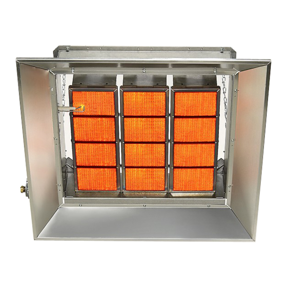
INFRARED RADIANT CERAMIC HEATER
DK SERIES
!INSTALLER:
This manual is the property of the owner. Please present this manual
to the owner when you leave the job site.
WARNING:
Improper installation, adjustment, alteration, service, or maintenance can
cause property damage, injury or death. Read the installation, operation
and maintenance instructions thoroughly before installing or servicing this
equipment.
In locations used for the storage of combustible materials, signs must be
posted to specify the maximum permissible stacking height to maintain
the required clearances from the heater to the combustibles. Signs must
either be posted adjacent to the heater thermostats or in the absence of
such thermostats, in a conspicuous location.
!IMPORTANT: SAVE THIS MANUAL FOR FUTURE REFERENCE.
SPACE-RAY
®
Post Office Box 36485
305 Doggett Street
Charlotte, North Carolina
(28236)
(28203)
Phone (704) 372-3485
Fax (704) 332-5843
www.spaceray.com
email: info@spaceray.com
Form #43219010
June 09
Advertisement
Table of Contents

Subscribe to Our Youtube Channel
Related Manuals for Space-Ray DK30


Summary of Contents for Space-Ray DK30
-
Page 1: Installation And Operation Instructions
Signs must either be posted adjacent to the heater thermostats or in the absence of such thermostats, in a conspicuous location. !IMPORTANT: SAVE THIS MANUAL FOR FUTURE REFERENCE. SPACE-RAY ® Post Office Box 36485 305 Doggett Street... -
Page 2: Table Of Contents
! WHAT TO DO IF YOU SMELL GAS: DO NOT try to light any appliance. Extinguish any open flame. Open windows. DO NOT touch any electrical switch. DO NOT use any telephone in your building. Immediately call your gas supplier from a neighbor’s telephone. Follow the gas supplier's instructions. -
Page 3: Safety
SAFETY This heater is a self-contained infrared radiant ceramic heater. Safety information required during installation and operation of this heater is provided in this manual and the labels on the product. The installation, service and maintenance of this heater must be performed by a contractor qualified in the installation and service of gas fired heating equipment. - Page 4 ! Children and adults should be alerted to the hazards of high surface temperatures and should stay away to avoid burns or clothing ignition. ! Clothing or other flammable materials should not be hung from the heater or placed on or near the heater. ! Young children should be carefully supervised when they are in the same space as the heater.
-
Page 5: Minimum Clearances To Combustibles
This heater is not an explosion proof heater. Where the possibility of exposure to volatile and low flash point materials exists, it could result in property damage or death. This heater must not be installed in a spray booth where the heater can operate during the spraying process. Consult your local fire marshal or insurance company. WARNING: Certain materials or objects, when stored under the heater, will be subjected to radiant heat and could be seriously damaged. -
Page 6: Hanging
“specify the maximum permissible stacking height to maintain the required clearances from the heater to combustibles.” Space-Ray recommends posting these signs adjacent to the heater thermostat or other suitable location that will provide enhanced visibility. -
Page 7: Dk Series Specifications
1/2” NPT (Female) *MOUNT HEATERS AS HIGH AS POSSIBLE. Minimums are shown as a guideline for human comfort and uniform energy distribution for complete building heating applications. Consult your Space-Ray representative for the particulars of your installation requirements. DK SERIES DIMENSIONS... -
Page 8: Gas Connections And Regulation
15-3/4” (40cm) 21/5/8” (55cm) 27-1/2” (70cm) 9” (23cm) 14-7/8” (38cm) 20-3/4” (53cm) Hanging Hanging Hanging Dimension Dimension Dimension 26-1/2” (67cm) 26-1/2” 26/1/2” 12” (30cm) (67cm) (67cm) Hanging Dimension (Typical all Models) 2-BURNER UNIT 1-BURNER UNIT 3-BURNER UNIT 33-3/8” (85cm) 26-5/8” (68cm) 3/8”... -
Page 9: Instructions For Pressure Test Gauge Connection
5. This appliance is equipped with a snap-opening, Certified connections are recommended to combination gas valve. The maximum supply be installed as shown, in one plane, and pressure to the appliance is 14” W.C. or 1/2 without sharp bends, kinks or twists. The P.S.I. -
Page 10: Electrical Connections
2. With the main burner operating, check the burner manifold pressure using a water manometer. The combination gas valve is factory set and should not be adjusted. If adjustment is required, remove the cover screw. Using a small screwdriver, turn the adjustment screw clockwise to increase, or counter-clockwise to decrease the gas pressure to burner. -
Page 11: Ventilation
VENTILATION This heater requires ventilation in the building to dilute the products of combustion and provide fresh air for efficient combustion. Power ventilation is recommended and the minimum vent flow required is as follows: DK30, DK33, DK35 128 cfm DK100... -
Page 12: Lighting And Shutdown Instructions
DK30, DK33, DK35 0.49 s/f DK100 1.48 s/f DK40 0.57 s/f DK120 1.72 s/f DK60, DK66, DK70 0.98 s/f DK132, DK140 1.97 s/f DK80 0.98 s/f DK160 2.30 s/f The General Ventilation Rules outlined in ASHRAE GUIDE AND DATA BOOK should be observed when locating vents. -
Page 13: Cleaning And Annual Maintenance
Disconnect power to heater before servicing. Do not operate unit if repairs are necessary. Do not operate unit showing any signs of burner malfunction. Call a professional for assistance. Avoid Equipment Failure. Do not blow out heating elements with high pressure air CLEANING AND ANNUAL MAINTENANCE This heater consists of multiple individual atmospheric burners. - Page 14 ground. The minimum flame current necessary to keep the system from lockout is 0.7 microamps. To measure the flame current, connect an analog DC microammeter to the FC- and FC+ terminals per diagram. The meter should read 0.7 µA or higher when the burner is running full on.
- Page 15 There is insufficient heat in the building Conduct heat loss and add heaters or for heat loss (i.e., not enough heaters). other source of heat as necessary. Heater will not The thermostat sensing bulb is Reposition as necessary for proper attain the desired incorrectly placed.
-
Page 16: Optional Parabolic Reflector Extension
Is there 24V at the Swap out the Check ignition cable Turn up thermostat Does the module module. See section Check the spark gap electrodes from a for continuity. to call for heat. Does have a steady red 8 for wiring. is it 3/16”? working heater, does Replace if necessary... -
Page 17: Optional Protective Reverb Screen
(END PANEL) below: DETAIL A Parabolic Reflector Extension (Section View) (SIDE PANEL) Parabolic Reflector Model No. Extension Kit Number DK30, DK33, DK35, DK40 #43822010 DK60, DK66, DK70, DK80 #43822020 DK100, DK120 #43822030 DK132, DK140, DK160 #43822040 OPTIONAL PROTECTIVE REVERB SCREEN... -
Page 18: Replacement Parts Guide
Orifice #41 for DK35, DK70, DK100, DK140 – Natural Gas 43862020 Manifold for DK60, DK66, DK70, DK80 43872980 Orifice 3/32” for DK30, DK60 – Natural Gas 43862030 Manifold for DK100, DK120 43872520 Orifice #52 for DK33, DK66, DK100, DK132 – Propane Gas... - Page 19 When presenting warranty claims, proof of date of purchase must be submitted. No Representative is authorized to assume for the manufacturer any liability except as set forth above. In case of claim under this warranty, contact: Space-Ray, P.O. Box 36485, 305 Doggett Street (28203), Charlotte, NC 28236, (704) 372-6391...
Need help?
Do you have a question about the DK30 and is the answer not in the manual?
Questions and answers