
Related Manuals for Worldlawn WYZ 48


Summary of Contents for Worldlawn WYZ 48
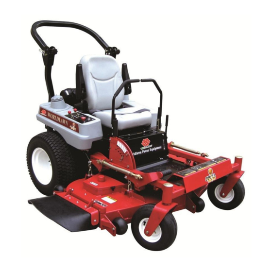
- Page 1 Operator’s Manual WYZ 48/52/60 Zero Turn Mower Worldlawn Power Equipment, Inc. 422 Turnbull Canyon Road, City of Industry, CA 91744 Toll Free Number:1-866-9-Mowers(1-866-966-9377)
- Page 2 OPERATOR’S MANUAL This manual contains assembly, operating, maintenance, adjustment and safety instructions for your WYZ 48/52/ WYZ60 lawn mower. Before operating your mower, carefully read this manual in its entirety. By following the operating, maintenance, adjustment and safety instructions, you will prolong the life of your mower, maintain its maximum efficiency and promote safe operation.
-
Page 3: Table Of Contents
TABLE OF CONTENTS …………………………………………………………………………………… SAFETY ………………………………………………………………… Safety Alert Symbol ……………………………………………………………………………. Training …………………………………………………………………………. Preparation …………………………………………………………………………... Operation ……………………………………………………………... Maintenance & Storage ………………………………………………………………………... Safety Signs ………………………………………………………………………… SPECIFICATIONS 2.1 Model Number…………………………………………………………………… 2.2 Engine……………………………………………………………………………. 2.3 Fuel System………………………………………………………………………. 2.4 Electrical System…………………………………………………………………. 2.5. Operator Controls……………………………………………………………….. 2.6. Seat………………………………………………………………………………. 2.7 Hydrostatic Ground Drive System……………………………………………….. - Page 4 4.2 Pre-Start……………………………………………………………………………. 20 4.3 Mowing…………………………………………………………….……………… 4.4 Transporting…………………………………………….……………………….… MAINTENANCE & ADJUSTMENTS………………………………………………………..…….. 5.1 Periodic Maintenance……………………………………………………………… ADJUSTMENTS ……………………………………………………………..……………….. …………………………………………………………………….. 34 TROUBLE SHOOTING …………………………………………………………….…….. . HYDRAULIC DIAGRAM ELECTRICAL DIAGRAM…………………………………………………………………………… WARRANTY…………………………………………………………………………………………….
-
Page 5: Safety
Worldlawn Power Equipment, Inc. avoid accidents. This symbol means: 1.3.2 The use of personal protective equipments, such as (but not limited to) protection for the eyes, ATTENTION! BECOME ALERT! ears, feet, and head is recommended. - Page 6 POTENTIAL HAZARD POTENTIAL HAZARD · In certain conditions gasoline is extremely · In certain conditions gasoline is extremely flammable and highly explosive. flammable and highly explosive. WHAT CAN HAPPEN WHAT CAN HAPPEN · A fire or explosion from gasoline can burn you, ·...
-
Page 7: Operation
POTENTIAL HAZARD POTENTAL HAZARD · Gasoline vapor can collect inside enclosed trailers · Operating engine parts, especially the muffler, and may be ignited by electrical sparks or hot becomes extremely hot. engine/exhaust components. WHAT CAN HAPPEN · Severs burns can occur on contact. WHAT CAN HAPPEN ·... - Page 8 POTENTIAL HAZARD · Mowing on wet grass or steep slopes can cause sliding and loss of control. WHAT CAN HAPPEN · Wheels dropping over edges, ditches, steep banks, or water can cause rollovers, which may result in Danger serious injury, death or drowning. Safe Zone Zone...
-
Page 9: Maintenance & Storage
guards, switches, and other devices in place and in 1.4.18 Be aware of the mower discharge and proper working condition. direct discharge away from others. 1.4.9. DO NOT change the engine governor 1.4.19. DO NOT operate the mower under the setting or overspend the engine. -
Page 10: Safety Signs
1.5.9. Check all bolts frequently to maintain your authorized equipment dealer or distributor or proper tightness. from Worldlawn Power Equipment, Inc. 1.5.10. Keep all guard, shields and all safety 1.6.5 Safety signs may be affixed by peeling off devices in place and in safe working condition. - Page 11 5. On The Mower Deck, RH 6. On The Mower Deck, LH 7. Center Of Console 8:Front Left Corner Of Console 11:On The Lower Roll 9:Back Of Hydraulic Fuel Tank 12:Top Left Corner Of 10:On The Front Frame Rear Front Frame...
- Page 12 13:On the Mower Deck 20:On the Mower Deck 14:Left Corner Of Mower Deck 21:Front Right Corner Of Console 15:On The Fuel Tank 22:On The Left Fuel Tank 16:On The Fuel Tank 23:On The Right Fuel Tank 17:On The Fuel Tank 24:On The Outer Height Adjustment Plate 18:Back Of Hydraulic Fuel Tank 25:Top Of Console, LH &...
-
Page 13: Specifications
30:Side Of Console, RH 27:Front Of Mower Deck, 48” 28:Front Of Mower Deck, 52” 31:Side Of Console, LH 32:Top Center Of Console 29:Front Of Mower Deck, 60” 2.SPECIFICATIONS 2.1 MODEL NUMBER: WYZ5222KW-H WY5222KW-H Model Hydraulic System H----Hydro-gear Cutting Width (inch) Engine HP Engine KH----Kohler... -
Page 14: Fuel System
2.2.2 RPM: Full Speed:3600RPM(No Load) Idle:1500RPM 2.3 FUEL SYSTEM 2.3.1 Capacity: 10.5 gal(40L) 2.3.2 Type of Fuel: Regular unleaded gasoline, 87 octane or higher. 2.3.3. Fuel Shut-Off Valve: left tank, & right tank 2.4 ELECTRICAL SYSTEM 2.4.1 Charging System: Flywheel Alternator 2.4.2 Charging Capacity: 15 amps 2.4.3 Battery Type:12V/33AH 2.4.4 Polarity: Negative Ground... -
Page 15: Tires And Wheels
2.7.1 Hydraulic System Specification Hydro Gear Hydraulic Pump Two 10cc Displacement pumps. Hydraulic Motors Two 250cc displacement With 31.75mm tapered shafts Hydrostatic Oil Type Synthetic Mobil 1 SAE 15W-50 Hydrostatic Oil Capacity 3.2qt.(3.0L.) Hydraulic Filter Replaceable cartridge type. Flow: 7L/min, Precision: 25 μm Speeds 15.3km/hr forward... -
Page 16: Dimension
2.9.6 Deck: Full floating deck is attached to out-front support frame. Maximum turf protection is provided by three anti-scalp rollers on 48’’ Deck & Five anti-scalp rollers on 52’’ & 60” decks. Deck design allows for bagging, mulching, and side discharge. 2.9.7 Cutting Height Adjustment: an extra-long cushioned lever (a foot operated deck lift assist lever to aid in raising the deck) used to adjust the cutting height from 1.5”... -
Page 17: Torque Requirements
2.11 TORQUE REQUIREMENTS Bolt Location Torque Cutter Housing Spindle Nut 190-197N-m Blade Mounting Bolt 156-163N-m Engine Deck/Front Frame Mount Bolts: 41-47 N-.m Nylon Rollover Bolts: 54-61 N-m Hydraulic Motor Mount Bolts 98-104N-m Wheel Hub Slotted Nut 169 N-m Rollover Protection System (Roll Bar) Mounting Bolts: 41-47 N-m Drive Wheel Mount Bolts 170N-m... -
Page 18: Service Battery
3.2.3 Install the two lower roll bar tubes. a) Locate the left and right lower roll bar tubes. b) Align lower roll bar tubes along wheel motor channels as show in Figure 2. c) LOOSELY install lower roll bar hardware. FIG 2. - Page 19 3.3.1 Unhook seat latch and tilt seat to gain access to the battery. POTENTIAL HAZARD ·Charging the battery may produce explosive gasses. WHAT CAN HAPPEN ·Battery gasses can explode causing serious injury. HOW TO AVOID THE HAZARD ·Keep sparks, flames, or cigarettes away from battery. Ventilate when charging or using battery in an enclosed space.
-
Page 20: Install Drive Wheels And Check Tire Pressure
negative battery cables and run the vehicle continuously for 20 to 30 minutes to sufficiently charge the battery. · Battery contains sulfuric acid, avoid contact and always shield eyes, face, skin and clothing from battery ,cigarettes, flames or sparks could cause battery to explode ·.Do not charge or use booster cables or adjust post connection without proper training;... -
Page 21: Position Discharge Chute
FIG4. MOTION CONTROL LEVER ASSEMBLY 3.7 POSITION DISCHARGE CHUTE Loose two nuts M8 attaching discharge chute. Lower the discharge chute into position. Retighten nuts until chute is snug but can pivot freely. 3.8 SERVICE ENGINE Engine is shipped with oil, check oil lever and if necessary fill to the appropriate lever with 10W-40 3.9. - Page 22 FIG 5 NEUTRAL LOCK POSITION By moving both levers an equal amount forward or back from the neutral position, the machine can be caused to move forward or backward in a straight line. Movement of the left lever forward will cause the left drive wheel to rotate in a forward direction. Movement of the right lever forward will cause the right drive wheel to rotate in a forward direction To stop forward travel, pull the lever back to the neutral position.
- Page 23 rear of the machine) to cause the machine to track more to the right and clockwise to cause the machine to track more to the left. Adjust in quarter-turn increments until the machine tracks straight. Check that the machine does not creep when in neutral with the park brakes disengaged. NOTE : Do not rotate the knob too far, as this may cause the creep in neutral;...
-
Page 24: Pre-Start
Hydra-Gear : Located on the right front corner of the hydrostatic pumps . With a 5/8 wrench, turn both valves one turn counter-clockwise to release drive system. Turn clockwise to reset system. DO NOT over tighten. DO NOT tow machine. White: Located on the right front corner of the hydrostatic pumps . -
Page 25: Transporting
POTENTIAL HAZARD ·The rotating blades under the mower deck are dangerous. WHAT CAN HAPPEN . Blade contact can cause serious injury or kill you. HOW TO AVOID THE HAZARD . DO NOT put hands or feet under the mower or mower deck when the blades are engaged. POTENTIAL HAZARD ·... - Page 26 POTENTIAL HAZARD · This unit does not have proper turn signals, lights, reflective markings, or a slow moving vehicle emblem. These items are required to drive on a public street or roadway. WHAT CAN HAPPEN · Driving on a street or roadway without such equipment is dangerous and can lead to accidents causing personal injury.
-
Page 27: Maintenance &Adjustments
5. MAINTENANCE &ADJUSTMENTS 5.1PERIODIC MAINTENACE 5.1.1Check the engine oil level: Service Interval: Daily a) Stop engine, wait for all moving parts to stop and make sure unit is on a level surface.b) b) Check with engine cold. c) Clean area around dipstick. Remove dipstick and wipe oil off. Reinsert the dipstick. Do not screw into place. - Page 28 IMPORTANT: Make sure the negative &positive battery cables are connected rightly, and the battery charger used for charging the battery has and output of 16 volts and 7 amps or less to avoid damaging the battery.(see chart 3.3.2 for recommended charger settings.) 5.1.
- Page 29 FIG6 BLADE INSTALLATION POTENTIAL HAZARD · Operating a mower deck with loose or weakened blade bolts can be dangerous. WHAT CAN HAPPEN · A loose or weakened blade could allow a blade rotating at a high speed to come out from under the deck, causing serious injury or property damage.
- Page 30 On Seat or Not. NOTE: If machine does not pass any of these tests, do not operate. Contact your authorized WORLDLAWN POWER EQUIPMENT SERVICE DEALER. IMPORTANT: It is essential that operator safety mechanisms be connected and in proper operating condition prior to use for mowing.
- Page 31 engine.. Place pan under machine to catch oil and open valve with wrench. Allow oil to drain then close valve. d) Replace the oil filter Every Other oil change. Clean around oil filter and unscrew filter to remove. Before reinstalling new filter, apply a thin coating of oil on the surface of the rubber seal. Turn filter clockwise until rubber seal contacts the filter adapter then tighten filter an additional 2/3 to 3/4 turn.
- Page 32 Service Interval: 160hrs. a) Stop engine, wait for all moving parts to stop, and remove key. b) Unhook seat latch and tilt seat up. c) Lubricate switch actuator rod with spray type lubricant or light oil. 5.1.16. Lubricate brake handle pivot: Service Interval: 160hrs.
-
Page 33: Adjustments
IMPORTANT: Before reinstalling new filter, fill it with Mobil 1 SAE 15W-50 and apply a thin coat of oil on the surface of the rubber seal. Turn the filters clockwise until rubber seal contacts the filter adapter then tighten the filter an additional 2/3 to 3/4 turn. - Page 34 stop, and remove key. Place rollers in one of the Position shown in Figure 7.Rollers will maintain 3/4 in. (19mm) clearance to the ground to minimize gouging and roller wear or damage. For Maximum Deck Flotation, place rollers one hole position lower. Rollers should maintain 1/4 in. (6.4mm) minimum clearance to ground.
- Page 35 Self-tensioning- No adjustment necessary. 5.2.4 Deck Belt Tension. Self-tensioning- No adjustment necessary. 5.2.5 Adjust Seat Switch. If necessary, adjust the seat actuator rod length to where the machine will shut off when the operator raises off the seat (with brake disengaged or PTO engaged) but will continue to run with operator in seat.
- Page 36 5.2.8 Adjust Throttle Lever Tension. a) Stop engine wait for all moving parts to stop, and remove key. b) Tension in throttle lever can be adjusted by adjusting the tightness of the lever pivot bolt, which is located under the console. 5.2.9 Electric Clutch Adjustment: No adjustment necessary.
-
Page 37: Trouble Shooting
f) The reverse indicator spring must be correct before the following adjustments can be made. NOTE: The motion control lever needs to be in neutral while making any necessary adjustments. The left rod assembly controls the left wheel and the right rod assembly controls the right wheel. g) Bring the RH motion control lever into the neutral position. -
Page 38: Mower Cuts Unevenly
b)Check air pressure in tires: 20psi/drive, 40psi/pneumatic casters. FIG12. Caster Adjustment 6.2 MOWER CUTS UNEVENLY. a) Check air pressure in tires; 20psi/drive, 40psi/penumatic casters. b) Check deck support chains. c) Check deck leveling (See Adjustments Section 5.2.2) Note: The front of the mower deck will be approximately 6 mm lower than the back of the mower deck;... - Page 39 ENGINE TROUBLESHOOTING TABLE DIRT IN DIRTY FAULTY DIRTY IMPROPE ENGINE BLOCKED INCORRECT PROBLEM FUEL SPARK FUEL R FUEL OVERLOADED FUEL FILTER OIL LEVER LINE FILTER PLUG SCREEN Will × × × × × × Start Hard × × × × ×...
-
Page 40: Hydraulic Diagram
7、HYDRAULIC DIAGRAM... -
Page 41: Electrical Diagram
8、ELECRICAL DIAGRAM... -
Page 42: Warranty
ARISING OUT OF ANY CAUSE WHATSOEVER, Worldlawn’s liability (as set forth below). WHETHER BASED CONTRACT, Any Mower or part thereof which , in worldlawn’s NEGLIGENCE OTHER TORT, sole discretion, is deemed defective shall be repaired STRICTLIABILITY, BREACH OF WARRANTY OR or replaced , at worldlawn’s option, without charge for... - Page 44 Worldlawn Power Equipment, Inc 422 Turnbull Canyon Road City of Industry CA 91744 phone:(626) 934-8552 fax: (626) 934-8162 E-mail: worldlawnmower@adelphia.net Form No . 52102-200901...
Need help?
Do you have a question about the WYZ 48 and is the answer not in the manual?
Questions and answers