
Related Manuals for Worldlawn WYZ 48


Summary of Contents for Worldlawn WYZ 48
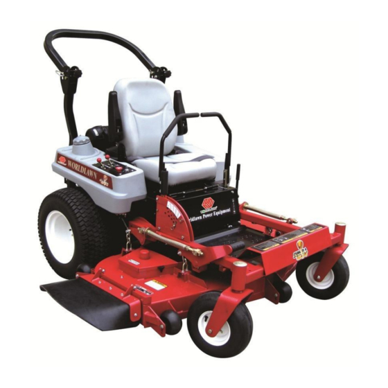
- Page 1 Operator’s Manual WYZ 48/52/60 Zero Turn Mower Worldlawn Power Equipment, Inc. Industrial Park 2415 Ashland Ave. Beatrice, NE 68310 Toll Free Number: 1-800-267-4255...
- Page 3 OPERATOR’S MANUAL This manual contains assembly, operating, maintenance, adjustment, and safety instructions for your WYZ 48/52/60 lawn mower. Before operating your mower, read this manual in its entirety carefully. By following the operating, maintenance, adjustment, and safety instructions, you will prolong the life of your mower, maintain its maximum efficiency, and promote safe operation.
-
Page 4: Table Of Contents
TABLE OF CONTENTS 1. SAFETY ………………………………………………………………………………… 1.1 Safety Alert Symbol………………………………………………………………… 1.2 Training………………………………………………………………………………. 1 1.3 Preparation ……………………………………………………………………….… 1.4 Operation ………………………………………………………………………...… 1.5 Maintenance & Storage …………………………………………………………...… 1.6 Safety Decals …………………………………………………………………...…… 2. SPECIFICATIONS……………………………………………………………………… 2.1 Model Number……………………………………………………………………… 2.2 Engine………………………………………………………………………………. 2.3 Fuel System…………………………………………………………………………. 2.4 Electrical System……………………………………………………………………. 2.5 Operator Controls ………………………………………………………………….. - Page 5 4.2 Pre-Start……………………………………………………………………………. 4.3 Mowing …………………………………………………………….……………… 4.4 Transporting …………………………………………….……………………….… 5. MAINTENANCE & ADJUSTMENTS……………………………..……..…………… 5.1 Periodic Maintenance ……………………………………………………………… 5.2 Adjustments ………………………..………………..……………………………… ……………………………………………………………….. 6. TROUBLESHOOTING ……………………………..………………………………… 7. HYDRAULIC DIAGRAM ……………………………………………………….…….. ……………………………………………………. 7.1 Hydraulic Pump Troubleshooting…………………………………………………… 8. ELECTRICAL DIAGRAM……………………………………………………………… 38 LIMITED WARRANTY …………………………………………………………………...
-
Page 6: Safety
1. SAFETY and safely perform the job. Only use accessories and 1.1 SAFETY ALERT SYMBOL attachments approved by Worldlawn Power Equipment, Inc. 1.3.2 The use of personal protective gear, such as This SAFETY ALERT SYMBOL is used both in this manual and on the machine to identify... - Page 7 POTENTIAL HAZARD POTENTIAL HAZARD · In certain conditions gasoline is extremely · In certain conditions gasoline is extremely flammable and highly explosive. flammable and highly explosive. WHAT CAN HAPPEN WHAT CAN HAPPEN · A fire or explosion from gasoline can burn you, ·...
-
Page 8: Operation
POTENTIAL HAZARD POTENTAL HAZARD · Gasoline vapor can collect inside enclosed trailers · Operating engine parts, especially the muffler, and may be ignited by electrical sparks or hot become extremely hot. engine/exhaust components. WHAT CAN HAPPEN WHAT CAN HAPPEN · Severs burns can occur on contact. ·... - Page 9 POTENTIAL HAZARD · Mowing on wet grass or steep slopes can cause sliding and loss of control. WHAT CAN HAPPEN · Wheels dropping over edges, ditches, steep banks, or water can cause rollovers, which may result in Danger serious injury, death or drowning. Safe Zone HOW TO AVOID THE HAZARD...
-
Page 10: Maintenance & Storage
guards, switches, and other devices in place and in direct discharge away from others. proper working condition. 1.4.17 DO NOT operate the mower under the 1.4.7 DO NOT change the engine governor influence of alcohol and / or drugs. setting or overspend the engine. Operating an engine 1.4.18 Use extra care when approaching blind at excessive speed may increase the hazard of personal corners, shrubs, trees, or other objects that may... -
Page 11: Safety Decals
1.6.4 New safety decals may be obtained from 1.5.9 Check all bolts frequently to maintain your authorized equipment dealer, distributor, or from Worldlawn Power Equipment, Inc. proper tightness. 1.5.10 Keep all guards, shields, and safety 1.6.5 Safety decals may be affixed by peeling off devices in place and in safe working condition. - Page 12 5. On the right side of the mower deck 6. On the left side of the mower deck 7. On the middle of the panel in front of the console 9. On the lower roll bar 10. On the top left corner 8.
- Page 13 11. On the mower deck 17. On the back of hydraulic fuel tank 18. On the right corner of rear deck 12. On the left side of mower deck 13. On the switch panel 19. On the front of the mower deck 14.
- Page 14 22. On the outer height adjustment plate 27. Front of mower deck, 60” 23. Top of the left and the right sides of the console 28. On the right side of the console DANGER To avoid serious injury or death: Avoid blades unless engine and blades are stopped.
-
Page 15: Specifications
2. SPECIFICATIONS 2.1 MODEL NUMBER: WYZ5222KW-H WYZ5222KW-H HYDRAULIC MODEL SYSTEM H-HYDRO-GEAR CUTTING WIDTH (INCH) ENGINE HP ENGINE KW-KAWASAKI 2.2 ENGINE 2.2.1 Engine specifications: See Your Engine Owner’s Manual 2.2.2 RPM: Full Speed: 3600RPM (No Load) Idle:1500RPM 2.3 FUEL SYSTEM 2.3.1 Capacity: 9.5 gal (36L) 2.3.2 Type of Fuel: Regular unleaded gasoline, 90 octane or higher. -
Page 16: Seat
2.5.2 PTO Switch: Engine electric clutch ( to drive belt) which engages mower blades. 2.5.3 Parking Brake Lever: Engages parking brakes. 2.5.4 Deck Height Adjustment Lever: Sets cutting height to desired position. Foot pedal used to assist in raising the deck. 2.6 SEAT 2.6.1 Type: Standard seat: high back, foam padded (internal spring suspension) with arm rests. -
Page 17: Dimensions
2.9.3 Blade Size: (3ea.) WYZ48 deck WYZ52 deck WYZ60 deck 16.5in(419mm)× 3 18in(457mm) × 3 20.5in(520mm) × 3 2.9.4 Blade Spindles: Solid steel spindles with 25mm bearings. 2.9.5 Deck Drive: Electric clutch mounted on vertical engine shaft. Blades are driven by one “B” Section belt (w/self-tensioning idler) direct from the engine. -
Page 18: Torque Requirements
2.10.6 Overall Weight: WYZ48 is 992 lbs (450 Kg) WYZ52 is 1025 lbs (465 Kg) WYZ60 is 1080 lbs (490Kg) 2.11 TORQUE REQUIREMENTS Bolt Location Torque Cutter Housing Spindle Nut 140-145ft-lb (190-197N-m) Blade Mounting Bolt 115-120ft-lb (156-163N-m) Engine Deck/Front Frame Mount Bolts 30-35ft-lb (41-47N-m) Nylon Rollover Bolts 40-45ft-lb (54-61N-m) -
Page 19: Assembly Instructions
3. ASSEMBLY INSTRUCTIONS 3.1 UNCRATE MOWER 3.2 INSTALL ROLLER PROTECTION SYSTEM (ROLL BAR) 3.2.1 Disassemble roll bar from the crate. Loosen rollover protection system (roll bar) mounting bolts in the crate. Take roll bar with its bolts out. 3.2.2 Raise the rear of the unit and support it with jack stands or equivalent support. POTENTIAL HAZARD ·... -
Page 20: Service Battery
FIG 3 U–Shaped Bar Installation 3.3 SERVICE BATTERY Battery posts, terminals, and related accessories contain lead compounds, chemicals known to cause cancer and reproductive harm. The machine is shipped with a filled lead acid battery without protection. 3.3.1 Unhook seat latch and tilt seat to gain access to the battery. POTENTIAL HAZARD ·... -
Page 21: Install Drive Wheels And Check Tire Pressure
POTENTIAL HAZARD ·If the ignition is in the “ON” position, there is potential for sparks and engagement of components. WHAT CAN HAPPEN · Sparks could cause an explosion or moving parts could accidently engage causing personal injury. HOW TO AVOID THE HAZARD ·... -
Page 22: Position Discharge Chute
lever so the bolts are in the center of the slots on the lever mounting plate and tighten until snug. Repeat on opposite side of unit. NOTE: There are two lever height options available. Place the bolts in the first and the third hole (from the top) to increase height of the levers or in the first and the third hole (from the bottom) to decrease the height of the levers. -
Page 23: Operation Instructions
4. OPERATION INSTRUCTIONS 4.1 CONTROLS 4.1.1 Familiarize yourself with all controls before operating the mower. 4.1.2 Motion Control Levers: Located on each side of the console. The left lever controls the flow of hydraulic oil from the left hydrostatic pump to the left drive wheel motor. - Page 24 POTENTIAL HAZARD · Machine can spin very rapidly by positioning one lever too much ahead of the other. WHAT CAN HAPPEN · Operator may lose control of the machine, which may cause damage to the machine or injury. HOW TO AVOID THE HAZARD ·...
-
Page 25: Pre-Start
number of hours that the engine has run. If ignition switch is left on without engine running, hour meter will not run. NOTE: This switch is not a low oil sensor and will not alert the operator if the engine oil is low. 4.1.10 Fuel Shut-Off Valve: Located directly below center of console. - Page 26 IMPORTANT:DO NOT crank the engine continuously for more than 10 seconds at a time. If the engine does not start, allow a 60 second cool-down period between starting attempts. Failure to follow these guidelines can burn out the starter. After starting a cold engine, gradually return choke to the “OFF” position as the engine warm up. On a warm engine, place the throttle midway between the “SLOW”...
-
Page 27: Transporting
4.4 TRANSPORTING 4.4.1 Transporting a unit: Use a heavy-duty trailer or truck to transport the machine. Lock brake and block wheels. Securely fasten the machine to the trailer or truck with straps, chains, cable, or ropes. Be sure that the trailer or truck has all necessary lighting and marking as required by law. -
Page 28: Maintenance & Adjustments
5. MAINTENANCE & ADJUSTMENTS 5.1 PERIODIC MAINTENANCE 5.1.1 Check the engine oil level: Service Interval: Daily a) Make sure unit is on a level surface, stop engine, and wait for all moving parts to stop. b) Engine should be cold before checking engine oil. c)Clean area around dipstick. - Page 29 5.1.4 Clean grass build-up under deck: Service Interval: Daily a) Stop engine, wait for all moving parts to stop, and remove key. b) Raise deck to the transport position. Lift the front of the unit and support unit using jack stands or equivalent support.
- Page 30 On Seat or Not. NOTE: If machine does not pass any of these tests, do not operate. Contact your authorized WORLDLAWN POWER EQUIPMENT SERVICE DEALER. IMPORTANT: It is essential that operator safety mechanisms be connected and in proper operating condition prior to use for mowing.
- Page 31 5.1.8 Check for loose hardware. Service Interval: Daily a) Stop engine, wait for all moving parts to stop , and remove key. b) Visually inspect machine for any loose hardware or any other possible problem. Tighten hardware or correct the problem before operating. 5.1.9 Service air cleaner.
- Page 32 b) Check tire pressure in drive tires: Proper inflation for Zhengxin tires is 13psi (89.7kpa) Proper inflation for Carlisle tires is 18psi (124.2kpa) c) Check tire pressure in Caster tires: Proper inflation for caster tires is 25psi (172.5kPa). 5.1.13 Check condition of belts: Service Interval: 40hrs Stop engine, wait for all moving parts to stop, and remove key.
- Page 33 c) Lubricate bronze bushing on each end of brake rod shafts with a spray type lubricant or a light oil. One shaft is located under the console .The other is below and behind the seat. 5.1.18 Lubricate motion control bronze bushing: Service Interval: 160hrs a) Stop engine, wait for all moving parts to stop, and remove key.
-
Page 34: Adjustments
g) Start engine and move throttle control ahead to full throttle position. Move the speed control levers to full speed and run for several minutes. Shut down machine and recheck oil level. Do not change hydraulic system oil (except for what can be drained when changing filter), unless it is felt the oil has been contaminated or been extremely hot. - Page 35 FIG 7 5.2.3 Deck Leveling: a) Position mower on a flat surface. b) Stop engine, wait for all moving parts to stop, and remove key. c) Check tire pressure in drive tires: Proper inflation for Zhengxin tires is13psi (89.7kpa) Proper inflation for Carlisle tires is 18psi (124.2kpa) d) Check tire pressure in Caster tires.
- Page 36 5.2.6 Adjust Seat Switch: If necessary, adjust the seat actuator rod length to where the machine will shut off when the operator raises off the seat (with brake disengaged or PTO engaged) but will continue to run with operator in seat.
- Page 37 5.2.9 Adjust Throttle Lever Tension: a) Stop engine wait for all moving parts to stop, and remove key. b) Tension in throttle lever can be adjusted by adjusting the tightness of the lever pivot bolt, which is located under the console. 5.2.10 Electric Clutch Adjustment: No adjustment necessary.
- Page 38 f) The reverse indicator spring must be correct before the following adjustments can be made. NOTE: The motion control lever needs to be in neutral while making any necessary adjustments. The left rod assembly controls the left wheel and the right rod assembly controls the right wheel. g) Bring the RH motion control lever into the neutral position.
-
Page 39: Troubleshooting
FIG 12 Caster Adjustment 6. TROUBLESHOOTING 6.1 MOWER PULLS LEFT OR RIGHT (W/LEVERS FULLY FORWARD). a) Refer to tracking Adjustment Section 4.1. 3. b) Check air pressure in tires (see 5.1.12). 6.2 MOWER CUTS UNEVENLY. a) Check air pressure in tires (see 5.1.12). b) Check deck support chains. - Page 40 When a problem occurs, do not overlook the simple causes. For example, starting problems could be caused by an empty fuel tank. The following table lists some of the common causes of trouble. Do not attempt to service or replace major items or any items that call for special timing of adjustments procedures. Have this work done by your Engine Service Dealer.
-
Page 41: Hydraulic Diagram
7. HYDRAULIC DIAGRAM... -
Page 42: Hydraulic Pump Troubleshooting
7.1 HYDRAULIC PUMP TROUBLESHOOTING Possible Cause Corrective Action Transaxle won't run in straight line Incorrect inflation on both sides. Refer to the inflation pressure offered by the manufacturer. To prevent the control connection rod from bending, loosening, Fix, adjust, or replace the control connection or not adjusting. -
Page 43: Electrical Diagram
8. ELECTRICAL DIAGRAM... -
Page 44: Limited Warranty
During the This warranty does not extend to any Mower or part warranty period, Worldlawn will repair or replace, at thereof which has been misused, neglected, damaged, its discretion, any Mower or part thereof which is abused, not properly installed or maintained, altered, found to be defective in material or workmanship. - Page 45 Notes:...
- Page 46 Notes:...
- Page 48 Worldlawn Power Equipment, Inc Industrial Park 2415 Ashland Ave. Beatrice, NE 68310 Phone: (402) 228-4255 Fax: (402) 223-4103 www.worldlawnpowerequip.com Form No. 52102-201110...
Need help?
Do you have a question about the WYZ 48 and is the answer not in the manual?
Questions and answers