
Related Manuals for Worldlawn WYRZ50


Summary of Contents for Worldlawn WYRZ50
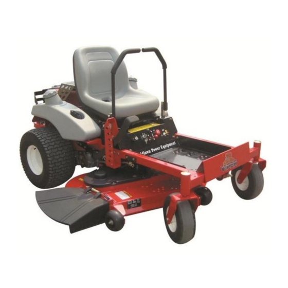
- Page 1 Operator’s Manual WYRZ50 Residential Zero Turn Mower Worldlawn Power Equipment, Inc. Industrial Park 2415 Ashland Ave. Beatrice NE 68310 Toll Free Number: 1-800-267-4255...
- Page 3 OPERATOR’S MANUAL This manual contains assembly, operating, maintenance, adjustment, and safety instructions for your WYRZ50 lawnmower. Before operating your mower, read this manual in its entirety carefully. By following the operating, maintenance, adjustment, and safety instructions, you will prolong the life of your mower, maintain its maximum efficiency, and promote safe operation.
-
Page 4: Table Of Contents
TABLE OF CONTENTS ……………………………………………………………………………………. SAFETY 1.1 Safety Alert Symbol ………………………………………………………………… 1.2 Training……………………………………………………………………………... 1.3 Preparation…………………………………………………………………………... 1.4 Operation…………………………………………………………………………..1.5 Maintenance & Storage ………………………………………………………..… 1.6 Safety Decals……………………………………………………………………..…………………………………………………………………………. SPECIFICATIONS 2.1 Model Number………………………………………………………………………. 2.2 Engine…………………………………………………………………………….…. 2.3 Fuel System 1………………………………………………………………………... 2.4 Fuel System 2….………………………………………………………………….…. 2.5 Electrical System………………………………………………………………….…. 9 2.6 Operator Controls………………………………………………………………..…... - Page 5 4.4 Transporting …………………………………………….……………………….…... 18 ……………………………………………………….. 19 MAINTENANCE & ADJUSTMENTS 5.1 Periodic Maintenance………………………………………………………………... 19 5.2 Adjustments……………………………………………………………………..…… ……………………………………………………………….. …………………………………………………………………….. TROUBLESHOOTING 6.1 Mower Pulls Left or Right ……………………………………………………..….. 6.2 Mower Cuts Unevenly ……………………………………………………..…….. 6.3 Engine Will Not Start ……………………………………………………..……..… 28 ………………………………………………………….……..30 ELECTRICAL DIAGRAM ……………………………………………….…….……….……...
-
Page 6: Safety
1.3 PREPARATION 1.3.1 Evaluate the terrain to determine what accessories and attachments are needed to properly and safely perform the job. Only use accessories and attachments approved by Worldlawn Power Equipment, Inc. - Page 7 POTENTIAL HAZARD POTENTIAL HAZARD · In certain conditions gasoline is extremely · In certain conditions gasoline is extremely flammable and highly explosive. flammable and highly explosive. WHAT CAN HAPPEN WHAT CAN HAPPEN · A fire or explosion from gasoline can burn you, ·...
-
Page 8: Operation
POTENTIAL HAZARD POTENTAL HAZARD · Gasoline vapor can collect inside enclosed trailers · Operating engine parts, especially the muffler, and may be ignited by electrical sparks or hot become extremely hot. engine/exhaust components. WHAT CAN HAPPEN WHAT CAN HAPPEN · Severe burns can occur on contact. ·... - Page 9 POTENTIAL HAZARD · Mowing on wet grass or steep slopes can cause sliding and loss of control. WHAT CAN HAPPEN · Wheels dropping over edges, ditches, steep banks, or water can cause rollovers, which may result in Danger Safe serious injury, death, or drowning. Zone Zone HOW TO AVOID THE HAZARD...
-
Page 10: Maintenance And Storage
Stop the engine and wait for all moving parts to stop: negative battery post when the unit will be allowed to Before refueling. sit for more than 30 days without use. Before dumping the grass catcher. 1.5.3 Allowing batteries to stand for an extended 1.4.13 Before stopping the engine, place the period of time without recharging them will result in between the “slow”... -
Page 11: Safety Decals
1.6.4 New safety decals may be obtained from your authorized equipment dealer or distributor or Worldlawn Power Equipment, Inc. from 1.6.5 Safety decals may be affixed by peeling off the backing to expose the adhesive surface. Apply 5. - Page 12 11. On the Switch Panel 6. On the Left Side of Mower Deck 7. On the Handle Grip of Choke Cable 12. On the Left Front Mower Deck 13. On the Left T-slot of Console 8. On the Inner Adjustable Height Bracket 14.
- Page 13 22. On the Right Front of Mower Deck, 50” 16. On the Left Rear Frame 23. On the Right of Console 17. On the Right Rear Frame 24. On the Rear of the Mower 18. Top Left Corner of the Rear of Front Frame 19.
-
Page 14: Specifications
2. SPECIFICATIONS 2.1 MODEL NUMBER: (Example: WYRZ5020BS) WYRZ5020BS 2.2 ENGINE 2.2.1 Engine specifications: See Your Engine Owner’s Manual 2.2.2 Maximum non-load speed: 3600 RPM 2.3 FUEL SYSTEM 1 2.3.1 Capacity: 3 gallons (12L) 2.3.2 Type of Fuel: Regular unleaded gasoline, 87 octane or higher. 2.3.3. -
Page 15: Operator Controls
Operator must be in the seat when PTO is engaged or one of the motion control levers are moved outward; or the engine will stop. 2.6 OPERATOR CONTROLS 2.6.1 Steering and Motion Control: Separate levers on each side of the console, control speed and direction of travel of the respective drive wheels. -
Page 16: Dimensions
(38mm) to 4.5” (114mm) in 0.5” (12.7mm) increments. There’s no need for the operator to stand to implement the height adjustment. 2.10.8 Mulching Kit: Optional. 2.10.9 Catching Kit: Optional. 2.11 DIMENSIONS WYRZ50 ( ) Overall Width Without deck 43.7 " (1110 mm) (... - Page 17 The machine is shipped with a filled lead acid battery without protection. 3.2.1 Unhook seat latch and tilt seat to gain access to the battery. POTENTIAL HAZARD · Charging the battery may produce explosive gasses. WHAT CAN HAPPEN · Battery gasses can explode causing serious injury. HOW TO AVOID THE HAZARD ·...
-
Page 18: Install Drive Wheels And Check Tire Pressure
· Battery contains sulfuric acid. Avoid contact and always shield eyes, face, skin, and clothing from battery. Cigarettes, flames, or sparks could cause battery to explode. · Do not charge or use booster cables or adjust post connections without proper training. ·... -
Page 19: Service Engine
FIG 2 Right Motion Control Lever Assembly e) If the ends of the levers hit against each other while in the drive position, make adjustments by moving the levers outward to the neutral lock position and carefully bending them outward. Move them back to the drive position and check for clearance, repeat if necessary. - Page 20 When the levers are centered in the T-slot, the drive system is in the neutral position. With levers moved out in the T-slot, the drive system is in the parking brake position. See Figure 4. FIG 4 PARKING BRAKE POSITION By moving both levers an equal amount forward or back from the neutral position, the machine can be moved forward or backward in a straight line.
- Page 21 POTENTIAL HAZARD · When going forward, if you rapidly pull the motion control levers to the middle T-slot position and push them out, it may cause the parking brake to lock. WHAT CAN HAPPEN · If the parking brake is locked, it may cause the machine not to move when trying to go forward again or rotate at high speed.
-
Page 22: Pre-Start
4.2 PRE-START 4.2.1 Fill fuel tanks. For best results use only clean, fresh, regular grade unleaded gasoline with an octane rating of 87 or higher. Regular grade leaded gasoline may also be used; however, combustion chamber and cylinder head will require more frequent service. See Engine Owner’s Manual. DO NOT add engine oil to gasoline. -
Page 23: Transporting
POTENTIAL HAZARD · An uncovered discharge opening will allow objects to be thrown in an operator’s or bystanders’ direction. Also contact with the blade could occur. WHAT CAN HAPPEN · Thrown objects or blade contact can cause serious injury or death. HOW TO AVOID THE HAZARD . -
Page 24: Maintenance & Adjustments
POTENTIAL HAZARD · Loading a unit on a trailer or truck increases the possibility of backward tip-over. WHAT CAN HAPPEN · Backward tip-over of the unit could cause serious injury or death. HOW TO AVOID THE HAZARD · Use extreme caution when operating a unit on a ramp. ·... - Page 25 5.1.2 Clean engine cooling system: Service Interval: Daily or more often in dry conditions POTENTIAL HAZARD · Excessive debris can cause the engine and hydraulic system to overheat. WHAT CAN HAPPEN · Excessive debris around the engine cooling air intake and inside of the pump compartment can create a fire hazard.
- Page 26 POTENTIAL HAZARD · Raising the mower deck for service or maintenance relying solely on mechanical or hydraulic jacks could be dangerous. WHAT CAN HAPPEN · The mechanical or hydraulic jacks may not be enough support or may malfunction allowing the unit to fall, which could cause injury.
- Page 27 NOTE: If machine does not pass each of these tests, do not operate. Contact your authorized WORLDLAWN POWER EQUIPMENT SERVICE DEALER. IMPORTANT: It is essential that operator safety mechanisms be connected and in proper operating condition prior to use for mowing.
- Page 28 d) Clean around oil fill cap and remove cap. Fill to specified capacity and replace cap. Use oil recommended in engine owner’s manual. DO NOT overfill. e) Start the engine and check for leaks. Stop engine and recheck oil level. 5.1.10 Check tire pressure: Service Interval: 40hrs a) Stop engine, wait for all moving parts to stop, and remove key.
-
Page 29: Adjustments
5.1.15 Check spark plugs: Service Interval: 160hrs Remove spark plugs, check condition and reset gaps, or replace the spark plugs. 5.1.16 Fuel tank- mounting hardware specification. Thread the specified M8 × 16 bolts with a lock washer and flat washer do not over tighten as this could cause damage to the fuel tank. - Page 30 FIG 7 e) See FIG 7. Position A is located in middle front of the mower deck. Position B is located behind the mower deck on each side. f) Reduce the mower deck to the position 1-1/2" ( 38mm) . Adjust the M10 nut with spanner on both sides. Ensure position B is 5 1/2"±...
- Page 31 5.2.7 Adjust Throttle Lever Tension. a) Stop engine wait for all moving parts to stop, and remove key. b) Tension in throttle lever can be adjusted by adjusting the tightness of the lever pivot bolt, which is located under the console. 5.2.8 Electric Clutch Adjustment: No adjustment necessary.
-
Page 32: Troubleshooting
e) Place the left motion control lever to the neutral position. Loosen the lock nut on the lever. Rotate the turnbuckle in the middle of the lever to adjust the length of left hydrostatic transaxle in proper way until the wheel stops. Pull the lever slightly when it’s in the neutral position. The motion control lever will rebound to the neutral position by the reaction power of spring. -
Page 33: Engine Will Not Start
Note: The front of the mower deck will be approximately 1/8"(3mm) lower than the back of the mower deck; this is called “rake” of the deck. e) Check blades tip to tip for straightness. 6.3 ENGINE WILL NOT START a) Make sure battery is at a full charge. b) Be sure the throttle control is midway between the “SLOW”... - Page 34 ENGINE TROUBLESHOOTING TABLE DIRT DIRTY FAULTY BLOCKED DIRTY IMPROPER ENGINE INCORRECT SPARK FUEL PROBLEM FUEL FUEL FUEL OVERLOADED OIL LEVEL FILTER PLUG FILTER SCREEN LINE Will not × × × × × × Start Hard × × × × × ×...
-
Page 35: Electrical Diagram
7. Electrical Diagram... -
Page 36: Limited Warranty
During the This warranty does not extend to any Mower or part warranty period, Worldlawn will repair or replace, at thereof which has been misused, neglected, damaged, its discretion, any Mower or part thereof which is abused, not properly installed or maintained, altered, found to be defective in material or workmanship. - Page 37 Notes:...
- Page 38 Notes:...
- Page 40 Worldlawn Power Equipment, Inc Industrial Park 2415 Ashland Ave. Beatrice, NE 68310 Phone: (402) 228-4255 Fax: (402) 223-4103 www.worldlawnpowerequip.com Form No. 50102-201111...
Need help?
Do you have a question about the WYRZ50 and is the answer not in the manual?
Questions and answers