
Related Manuals for TTI TCB-1100


Summary of Contents for TTI TCB-1100
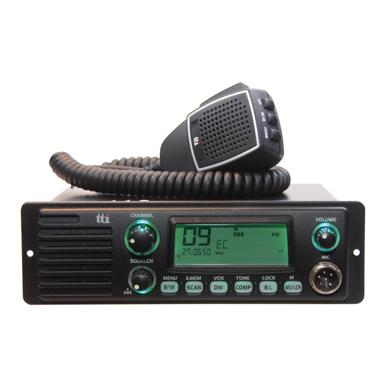
- Page 1 SERVICE MANUAL Downloaded from www.cbradio.nl MULTI CHANNEL AM/FM TRANSCEIVER TCB-1100 TTI Tech Co.,Ltd.
-
Page 2: Table Of Contents
TABLE OF CONTENTS SECTION SPECIFICATIONS SECTION CIRCUIT DESCRIPTION GENERAL TECHNICAL DESCRIPTION SEMICONDUCTORS AND FUNCTION DESCRIPTION OF FREQUENCY DETERMINING AND STABILIZING CIRCUIT TEST EQUIPMENT SETUP AND ALIGNMENT INSTRUCTIONS SECTION PART LIST SECTION MECHANICAL DISASSEMBLY SECTION 5 BOARD LAYOUT MAIN PCB LCD PCB LED PCB VOLUME PCB SQUELCH PCB... -
Page 3: Specifications
SECTION 1. SPECIFICATIONS General General Channel 40 (See the frequency band Frequency Range chart) Operating mode 26.96 MHz ~ 27.99125 MHz Frequency Control F3E (FM), A3E (AM) Frequency Tolerance PLL Synthesizer Operating Temperature 0.002% Range -10 to + 55 C Microphone Plug-in Type Input Voltage... -
Page 4: Circuit Description
SECTION 2. CIRCUIT DESCRIPTION ------------ Contents ------------- General 1-1. Receiver 1.2. Transmitter Technical Description 2-1. General 2-2. Type of emission 2-3. Frequency Table 2-4. RF Power Output 2-5. DC input Voltage and Current with 13.2V DC Input to Power AMP 2-6. -
Page 5: Receiver
TCB- 1100 Circuit Description Page 2 General 1-1. Receiver ① Display : 40 Channels and other functions indication ② Frequency Range : 26.965 to 27.405 [MHz] ③ Frequency Response : 300 to 2,500 [Hz] ④ Power Source : 13.2 [V] DC ⑤... -
Page 6: Type Of Emission
Page 3 Technical Description 2-1. General Model TCB-1100 is an mobile type AM/FM radio transceiver for use of the Citizen Radio Service. Front Panel Controls (1) LCD (Channel and RX/TX). (2) Receiver Audio Control Volume (With Power ON/OFF Control) (3) Squelch Control Volume (With DSS ON/OFF Control) -
Page 7: Frequency Table
TCB-1100 Circuit Description Page 4 2-3. Frequency Table Channel Frequency (MHz) Channel Frequency (MHz) 26.965 27.215 26.975 27.225 26.985 27.235 27.005 27.245 27.015 27.255 27.025 27.265 27.035 27.275 27.055 27.285 27.065 27.295 27.075 27.305 27.085 27.315 27.105 27.325 27.115 27.335 27.125... - Page 8 TCB-1100 Circuit Description Page 5 Semiconductors and Function 3-1. Transistor -------------------------------------------------------------------------------------------------------------------------------------------- Ref No. Description Manufacturer Function -------------------------------------------------------------------------------------------------------------------------------------------- Q101 2SC4226 RX Amplifier Q102 KTK211 1’st Mixer Q103 KTK211 1’st Mixer Q107 KTC3875S RX,RF/Mute,at-TX Q108 KTC3875S Q109 KTC3875S Q110 KRC112S S-Meter Dectector...
- Page 9 TCB-1100 Circuit Description Page 6 KTA1505S Back-Light,LED-Control KRC101S Back-Light,LED-Control KRC101S Back Light LED Control KRC101S Back Light LED Control KRC110S Back Light,LED Control 3-2. -------------------------------------------------------------------------------------------------------------------------------------------- Ref No. Description Manufacturer Function -------------------------------------------------------------------------------------------------------------------------------------------- SL5019 IF IC KIA358F AGC, Squelch Control TDA2003 AF Power Amplifier...
-
Page 10: Introduction
TCB-1100 Circuit Description Page 7 Description of Frequency Determining and Stabilizing Circuit 4-1. Introduction The Frequencies for transmitter and receiver first local frequencies are all derived from a signal 4.5MHz crystal by means of a phase locked loop(PLL). The first local oscillator frequencies are 37.660MHz(CH1) to 38.10MHz(CH40). The second local frequency is fixed at 10.240MHz to generate second IF 455KHz. - Page 11 TCB-1100 Circuit Description Page 8 Transmit CH 1 , 26.965 MHz 26.965 MHz Transmit CH 40 , 27.405 MHz 27.405 MHz Since all frequencies are obtained from the crystal controlled PLL oscillator, all outputs are coherent with the crystal oscillator frequency and matching the sample percentage accuracy.
-
Page 12: Descriptions Of Each Block
TCB-1100 Circuit Description Page 9 4-3. Descriptions of Each Block 4-3-1. Introduction The synthesizer is implemented with the following components; PLL IC (IC4) X-TAL (X102) VCO, VARICAP DIODE (D112) IC4 is CMOS LSI that includes most of PLL block. The Q128, L301, C232, C242, C243, C244, varicap diode D112 are clap oscillator circuit to operate as a VCO of the IC4. -
Page 13: Transmitter Buffer Amp
TCB-1100 Circuit Description Page 10 4-3-7. Transmitter Buffer The output signal of Q129, L3 goes to an amplifier with tuning circuit Q134, L701, which buffer incoming 26MHz signals. 4-3-8. Switching of Turning Capacitor in VCO The VCO circuit must tune with a wide range of frequencies 26.965MHz ~ 27.405MHz for transmitter and 37.66MHz ~38.10MHz for receiver. -
Page 14: Description Of Other Circuits
TCB-1100 Circuit Description Page 11 4-5. Description of other Circuits 4-5-1. Transmitter RF Amplification RF carrier frequencies are obtained at the output of buffer amplifier Q134 and turning IFT coil L701, The input of VCO frequencies 26MHz is selected at the buffer output, The output of buffer amplifier Q134 is fed through turning IFT coil L701, L703 to the base of pre driver amplifier Q135. -
Page 15: Receiver
TCB-1100 Circuit Description Page 12 4-5-2. Receiver Overload protection is provided to receiver’s semiconductors by diode D101. These diodes have a little effect on the incoming signal from another CB station; they protect the receiver from stray transmitter energy. In the receiver mode of operation, Q142 transistor is turned on. Also bias voltage is applied to Q101, Q102, Q103, IC1. -
Page 16: Test Equipment Setup And Test Procedure With Alignment Instructions
TCB-1100 Circuit Description Page 13 Test Equipment Setup and Test Procedure with Alignment Instructions General Section 5-1-1 Test Equipment Required • DC power supply(13.8V/3A) • DC Voltmeter or Oscilloscope • RF attenuator (30dB) 5-1-2 Test Procedure and Alignment Step Setting... - Page 17 TCB-1100 Circuit Description Page 14 Transmitter Section 5-2-1 Test Equipment Required • RF Power Meter • DC power supply(13.8V/3A) • 50 ohms load (non-inductive) • Spectrum analyzer • RF attenuator (30dB) • Frequency counter • Oscilloscope • Coupler • Audio generator •...
- Page 18 TCB-1100 Circuit Description Page 15 FM Deviation Adj. Connection the audio RV107 1.8KHz ~ Channel & Frequency : generator (set to 1 KHz)to the 2.0KHz 19CH, 27.185MHz microphone. MIC : Transmit Connect the modulation meter Function : FM Mode through the RF attenuator to the ANT Connector.
-
Page 19: Test Procedure With Alignment
TCB-1100 Circuit Description Page 16 Receiver Section 5-3-1 Test Equipment Required • Standard Signal Generator(SSG) • DC power supply(13.8V/3A) • AC Level Meter • Distortion Meter • Oscilloscope • SINAD Meter • 8 ohm Dummy Load 5-3-2 Test Procedure with Alignment... - Page 20 TCB-1100 Circuit Description Page 17 2009-02-20...
-
Page 21: Part List
SECTION 3. PART LIST NO PART NUMBER DESCRIPTION VENDOR LOCATION NO. 5A0-1100-000 MAIN PCB ASS′Y - TCB1100 1.00 112-100J-S00 METAL OXID RESISTOR 10OHM 2W +-5 ST 1.00 R181 142-000J-000 CHIP RES. 0603 0OHM +-5 PHILIPS 2.00 R139A R119 142-100J-000 CHIP RES. 0603 10OHM +-5 PHILIPS 1.00 R222 R104 R107 R143 R158 R159 R243 R305 R310 R179... - Page 22 54 204-4770-M00 ELECT CAP. 470UF 35V 10x16 1.00 C363 55 212-010C-6C0 CHIP CERAMIC CAP. 0603 1PF NP0 50V +-0.25 PHILIPS 1.00 C341 56 212-030C-6C0 CHIP CERAMIC CAP. 0603 3PF NP0 50V +-0.25 PHILIPS 1.00 C251 57 212-050C-6C0 CHIP CERAMIC CAP. 0603 5PF NP0 50V +-0.25 PHILIPS 1.00 C127 58 212-080C-6C0 CHIP CERAMIC CAP.
- Page 23 114 33C-2576-A00 IC DD CONVERTER KIA2576PI00 KEC 1.00 IC11 115 33C-4094-A00 IC BU4094BCFV ROHM 1.00 IC10 116 340-0230-A00 DIODE ZENER Z02W3.0V SOT-23 KEC 2.00 D106 D122 117 340-0256-A00 DIODE ZENER Z02W5.6V SOT-23 KEC 1.00 D118 118 340-0291-A00 DIODE ZENER Z02W9.1V SOT-23 KEC 1.00 D119 119 341-0251-A00 DIODE VARICAP KDV251S SOT-23 KEC...
- Page 24 177 142-471J-000 CHIP RES. 0603 470OHM +-5 PHILIPS 2.00 R31 R36 178 142-472J-000 CHIP RES. 0603 4.7KOHM +-5 PHILIPS 1.00 179 142-473J-000 CHIP RES. 0603 47KOHM +-5 PHILIPS 7.00 R9 R15 R17 R19 R26 R27 R28 180 142-681J-000 CHIP RES. 0603 680OHM +-5 PHILIPS 1.00 181 142-682J-000 CHIP RES.
- Page 25 278 834-C770-MC1 MIC LOGO STICKER PE 34.6*6.6*0.3T(REV.01) 1.00 279 834-CBCH-ST1 CB CHANNEL STICKER COPPER PAPER 100g/201X140mm 1.00 280 834-ROTE-R00 ROSTEST MARK STICKER 1.00 281 837-0001-000 OPP TAPE 50MM TTI LOGO 0.29 282 838-0001-000 YELLOW STRAP 0.26 283 83A-0001-000 SILICA GEL 1g 1.00 284 905-1100-000 MICROPHONE ASS′Y - TCB1100...
- Page 26 703-C7700- SPK HOLDER RUBBER BLACK 1.00 LONGSHENDA 703-C7700- MIC BUSHING RUBBER BLACK 1.00 LONGSHENDA 708-26102- SCREW TAP(+) 2.6X10L-2S BLACK FH 1.00 708-26162- SCREW TAP(+) 2.6X16L-2S BLACK PH 4.00 718-R000D- CUSHION SPK20X24X8.0T(1SIDE DOUBLE TAPE)EVA SPONGE 1.00 BONSO 718-R000N- MIC SPONGE 30X7X3T (NO TAPE) EVA SPONGE BLACK 1.00 BONSO 723-C7700-...
-
Page 27: Mechanical Disassembly
SECTION 4. MECHANICAL DISASSEMBLY... -
Page 29: Board Layout
SECTION 5. BOARD LAYOUT 5-1.Main PCB (Top Side) -
Page 30: Main Pcb
Main PCB (Bottom Side) -
Page 31: Lcd Pcb
5-2. LCD PCB (Top Side) - Page 32 LCD PCB (Bottom Side)
-
Page 33: Led Pcb
5-3. LED PCB (Top Side) - Page 34 LED PCB (Bottom Side)
-
Page 35: Volume Pcb
5-4. Volume PCB (Top Side) - Page 36 Volume PCB (Bottom Side)
- Page 37 5-5. Squelch PCB (Top Side)
-
Page 38: Squelch Pcb
Squelch PCB (Bottom Side) - Page 39 5-6. Channel PCB (Top Side)
-
Page 40: Channel Pcb
Channel PCB (Bottom Side) -
Page 41: Block Diagram
SECTION 6. BLOCK DIAGRAM... - Page 42 SECTION 7. SCHAMETIC...
Need help?
Do you have a question about the TCB-1100 and is the answer not in the manual?
Questions and answers