Advertisement
Quick Links
Download this manual
See also:
Instruction Manual
Downloaded from www.cbradio.nl
SERVICE
MANUAL
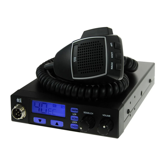
MULTI CHANNEL AM/FM TRANSCEIVER
TCB-660
TTI Tech Co.,Ltd.
Advertisement

Subscribe to Our Youtube Channel
Related Manuals for TTI TCB-660


Summary of Contents for TTI TCB-660
- Page 1 Downloaded from www.cbradio.nl SERVICE MANUAL MULTI CHANNEL AM/FM TRANSCEIVER TCB-660 TTI Tech Co.,Ltd.
- Page 2 TABLE OF CONTENTS SECTION SPECIFICATIONS SECTION CIRCUIT DESCRIPTION GENERAL TECHNICAL DESCRIPTION SEMICONDUCTORS AND FUNCTION DESCRIPTION OF FREQUENCY DETERMINING AND STABILIZING CIRCUIT TEST EQUIPMENT SETUP AND ALIGNMENT INSTRUCTIONS SECTION PART LIST SECTION MECHANICAL DISASSEMBLY SECTION BOARD LAYOUT MAIN PCB FRONT PCB VOLUME PCB SECTION BLOCK DIAGRAM...
-
Page 3: Specifications
SECTION1 SPECIFICATIONS Channel 40 (See the frequency band chart) Frequency Range 26.96 MHz ~ 27.99125 MHz Operating mode F3E (FM), A3E (AM) Frequency Control PLL Synthersizer Frequency Tolerance 0.002% Operating Temperature Range -10 to + 55 C Microphone Plug-in Type Input Voltage 13.2V DC ±... -
Page 4: Section2 Circuit Description
SECTION2 CIRCUIT DESCRIPTION ------------ Contents ------------- General 1-1. Receiver 1.2. Transmitter Technical Description 2-1. General 2-2. Type of emission 2-3. Frequency Table 2-4. RF Power Output 2-5. DC input Voltage and Current with 13.2V DC Input to Power AMP 2-6. Receiver IF and Local Oscillator Frequencies Semiconductors and Function Description of Frequency Determining and Stabilizing Circuit... - Page 5 TCB-660 Circuit Description Page 2 General 1-1. Receiver Display : 40 Channels and other functions indication Frequency Range : 26.965 to 27.405 [MHz] Frequency Response : 300 to 2,500 [Hz] Power Source : 13.2 [V] DC Audio Output Load : 8 [OHM] Audio Output : 4.0 [W] (or More)
- Page 6 Page 3 Technical Description 2-1. General Model TCB-660 is an mobile type AM/FM radio transceiver for use of the Citizen Radio Service. Front Panel Controls LCD (Channel and RX/TX). Receiver Audio Control (With Power ON/OFF Control) Volume Squelch Control Volume...
- Page 7 TCB-660 Circuit Description Page 4 2-3. Frequency Table Channel Frequency (MHz) Channel Frequency (MHz) 26.965 27.215 26.975 27.225 26.985 27.235 27.005 27.245 27.015 27.255 27.025 27.265 27.035 27.275 27.055 27.285 27.065 27.295 27.075 27.305 27.085 27.315 27.105 27.325 27.115 27.335 27.125...
- Page 8 TCB-660 Circuit Description Page 5 Semiconductors and Function 3-1. Transistor -------------------------------------------------------------------------------------------------------------------------------------------- Ref No. Description Manufacturer Function -------------------------------------------------------------------------------------------------------------------------------------------- Q101 KTC3880S RX Amplifier Q102 KTK211 1’st Mixer Q103 KTK211 1’st Mixer Q104 KRC101S RX Band1 Switching Q105 KRC101S RX Band2 Switching Q151...
- Page 9 TCB-660 Circuit Description Page 6 Q951 KTA1241 Back Light LED Control Q952 KTA1241 Back Light LED Control Q953 KRC101S Back Light LED Control Q954 KRC101S Back Light LED Control Q961 KRC110S TX AF Mute at RX Mode Q962 KRC111S MIC AF Path at AM Mode 3-2.
- Page 10 TCB-660 Circuit Description Page 7 Description of Frequency Determining and Stabilizing Circuit 4-1. Introduction The Frequencies for transmitter and receiver first local frequencies are all derived from a signal 4.5MHz crystal by means of a phase locked loop(PLL). The first local oscillator frequencies are 16.270MHz(CH1) to 16.710MHz(CH40). The second local frequency is fixed at 10.240MHz to generate second IF 455KHz.
- Page 11 TCB-660 Circuit Description Page 8 Transmit CH 1 , 13.4825 MHz 26.965 MHz Transmit CH 40 , 13.7025 MHz 27.405 MHz Since all frequencies are obtained from the crystal controlled PLL oscillator, all outputs are coherent with the crystal oscillator frequency and matching the sample percentage accuracy.
- Page 12 TCB-660 Circuit Description Page 9 Program Data & Frequency[Table 1] Frequency Channel [MHz] Fvco Fvco 26.965 3254 16.27 5393 13.4825 26.975 3256 16.28 13.4875 5395 26.985 3258 16.29 13.4925 5397 27.005 3262 16.31 13.5025 5401 27.015 3264 16.32 13.5075 5403 27.025...
- Page 13 TCB-660 Circuit Description Page 10 4-3. Descriptions of Each Block 4-3-1. Introduction The synthesizer is implemented with the following components; PLL IC (IC301) X-TAL (X301) VCO, VARICAP DIODE (D301) IC1301 is CMOS LSI that includes most of PLL block. The Q301, L301, C311, C312, C313, C314, varicap diode D301 are clap oscillator circuit to operate as a VCO of the IC301.
-
Page 14: First Mixer
TCB-660 Circuit Description Page 11 4-3-7. Transmitter Doublers The output signal of Q302, L302 goes to an amplifier with tuning circuit Q701, L701, L702 which doubles incoming 13MHz signals. 4-3-8. Switching of Turning Capacitor in VCO The VCO circuit must tune with a wide range of frequencies 13.4825MHz ~ 13.7025MHz for transmitter and 16.27MHz ~16.71MHz for receiver. - Page 15 TCB-660 Circuit Description Page 12 4-5. Description of other Circuits 4-5-1. Transmitter RF Amplification RF carrier frequencies are obtained at the output of doublers amplifier Q701 and turning IFT coil L701, L702. The input of VCO frequencies 13MHz is selected at the doublers output, which creates the necessary 27MHz.
- Page 16 TCB-660 Circuit Description Page 13 4-5-2. Receiver Overload protection is provided to receiver’s semiconductors by diode D101. These diodes have a little effect on the incoming signal from another CB station; they protect the receiver from stray transmitter energy. In the receiver mode of operation, Q923 transistor is turned on. Also bias voltage is applied to Q101, Q102, Q103, Q106.
- Page 17 TCB-660 Circuit Description Page 14 Test Equipment Setup and Alignment Instructions General Section 5-1-1 Test Equipment Required • DC power supply(13.8V/3A) • DC Voltmeter or Oscilloscope • RF attenuator (30dB) 5-1-2 Alignment Procedure Step Setting Connection Adjuster Adjust for RX VCO voltage Adj.
- Page 18 TCB-660 Circuit Description Page 15 Transmitter Section 5-2-1 Test Equipment Required • RF Power Meter • DC power supply(13.8V/3A) • 50 ohms load (non-inductive) • Spectrum analyzer • RF attenuator (30dB) • Frequency counter • Oscilloscope • Coupler • Audio generator •...
- Page 19 TCB-660 Circuit Description Page 16 FM Deviation Adj. Connection the audio RV401 1.8KHz ~ Channel & Frequency : generator (set to 1 KHz)to the 2.0KHz 19CH, 27.185MHz microphone. MIC : Transmit Connect the modulation meter Function : FM Mode through the RF attenuator to CB/ANL Off/DX the ANT Connector.
- Page 20 TCB-660 Circuit Description Page 17 Receiver Section 5-3-1 Test Equipment Required • Standard Signal Generator(SSG) • DC power supply(13.8V/3A) • AC Level Meter • Distortion Meter • Oscilloscope • SINAD Meter • 8 ohm Dummy Load 5-3-2 Alignment Procedure Step...
- Page 21 TCB-660 Circuit Description Page 18 2007-02-23...
- Page 22 SECTION3 PART LIST PART LIST of TCB-660 Rev. 05 09-Feb-07 NAME & DESCRIPTION VENDOE CODE Q'ty Location NO ITEM MAKER VENDOR ASS'Y REMARKS * ELECT Parts COVER ASS'Y SPEAKER 66mm 66AR000-8P-4K11 ASAHI ASAHI SPK201 WIRE HARNESS PH-2PIN TO OPE UL1007 #26 L=200mm FINE...
- Page 23 MAKER VENDOR ASS'Y REMARKS IC EEPROM AT24C02 (SOP-8) ATMEL IC802 IC CPU (FLASH) WITH TCB660 SOFTWARE JT5BL9 TOSHIBA IC801 LCD DISPLAY SDM8A3926C FOR TCB-660 SANTECH LCD801 SW801, SW802, SW806, SW807, SW TACT TS-1109 HENGRONG SW808 RESONATOR 4.0MHz ZTA4.00MG D.TRON D.TRON...
- Page 24 NAME & DESCRIPTION VENDOE CODE Q'ty Location NO ITEM MAKER VENDOR ASS'Y REMARKS R131, R203, R237, R307, R402, CHIP RESISTOR 2.2K 1/16W 5% T 1608 PHILIPS R817, R822, R912, R922, R923, R961, R01 R132, R162, R175, R302, R304, CHIP RESISTOR 1/16W 5% T 1608 PHILIPS R305...
- Page 25 NAME & DESCRIPTION VENDOE CODE Q'ty Location NO ITEM MAKER VENDOR ASS'Y REMARKS C152, C163, C164, C165, C310, CHIP CERAMIC 0.047UF 1608 PHILIPS/SAMSUNG C721, C914 CHIP CERAMIC 0.47UF 1608 PHILIPS/SAMSUNG C212 CHIP CERAMIC 0.068UF 1608 PHILIPS/SAMSUNG C410 CHIP CERAMIC 10PF 1608 PHILIPS/SAMSUNG C96, C113, C324...
- Page 26 NAME & DESCRIPTION VENDOE CODE Q'ty Location NO ITEM MAKER VENDOR ASS'Y REMARKS 116 CHIP TRANSISTOR KTA1504S SOT-23 Q164, Q233, Q912, Q924 Q151, Q181, Q182, Q183, Q234, 117 CHIP TRANSISTOR KTC3875S SOT-23 Q742, Q921, Q923, Q931 Q101, Q161, Q162, Q301, Q302, 118 CHIP TRANSISTOR KTC3880S SOT-23...
- Page 27 NAME & DESCRIPTION VENDOE CODE Q'ty Location NO ITEM MAKER VENDOR ASS'Y REMARKS 152 TRANSFORMER CHOKE FINE FINE T901 153 TRANSFORMER EI-24(MOD.) FINE FINE T201 154 IFT COIL RF FREE TX 27MHz FINE FINE L701, L702 155 COIL AXIAL 0.47uH LAL03TR0R47K L703,L302 156 IFT COIL...
- Page 28 Capacitor 103P ±10% 0603 103P Sw Push SKPS-2210C Sw Tact SKTS-1102A MIC Condensor 4.5V 2.2K -44db ±2db PF0-9765P-LP Curl Code 5CORD 1SIELD FINE FINE MIC Connector HS6-TTI 16-6P HYESUNG LEAD WIRE BLK 3:3 65m AWG28/1571 LEAD WIRE RED 3:3 65m AWG28/1571...
- Page 29 NAME & DESCRIPTION VENDOE CODE Q'ty Location NO ITEM MAKER VENDOR ASS'Y REMARKS <MECHANICAL> BOTTOM COVER ABS, BLACK PBOT130000-003 YiSheng UPPER COVER ABS, BLACK PTOP130000-003 YiSheng DECO ABS, SILVER PDEC130000-003 YiSheng PUSH LEVER ABS, BLACK PPUL130000-003 YiSheng KNOB ABS, BLACK PKNB130000-003 YiSheng HOLDER...
- Page 30 SECTION4 MECHANICAL DISASSEMBLY...
- Page 31 PART NAME DESCRIPTION REMARK Upper cover SPC 0.75t, Black Bottom cover SPC 0.75t, Black Main body EGI, 1.0t Bracket(Set) SPC 1.6t, Blacke Key PCB 1.6t Main PCB 1.6t Ch knob ABS, Black LED PCB 1.0t Nut for Mic connector Washer for Mic connector Escutcheon ABS, Black Double tape(Window)
-
Page 32: Board Layout
SECTION5 BOARD LAYOUT 5-1 Main PCB (Top side) - Page 33 Main PCB (Top Silk)
- Page 34 Main PCB (Bottom side)
- Page 35 Main PCB ( Bottom Silk)
- Page 36 5-2 Front PCB (Top Side)
- Page 37 Front PCB (Top Silk)
- Page 38 Front PCB (Bottom Side)
- Page 39 Front PCB (Bottom silk)
- Page 40 5-3 Volume PCB (Top Side)
- Page 41 Volume PCB (Bottom Side)
- Page 42 SECTION6 BLOCK DIAGRAM...
- Page 43 SECTION7 SCHEMATIC...
Need help?
Do you have a question about the TCB-660 and is the answer not in the manual?
Questions and answers