
Related Manuals for TTI TCB-880


Summary of Contents for TTI TCB-880
- Page 1 Downloaded from www.cbradio.nl SERVICE MANUAL MULTI CHANNEL AM/FM TRANSCEIVER TCB-880 TTI Tech...
- Page 2 TABLE OF CONTENTS SECTION SPECIFICATIONS SECTION CIRCUIT DESCRIPTION GENERAL TECHNICAL DESCRIPTION SEMICONDUCTORS AND FUNCTION DESCRIPTION OF FREQUENCY DETERMINING AND STABILIZING CIRCUIT TEST EQUIPMENT SETUP AND ALIGNMENT INSTRUCTIONS SECTION PART LIST SECTION MECHANICAL DISASSEMBLY SECTION BOARD LAYOUT MAIN PCB FRONT PCB LED PCB VOLUME PCB MIC PCB...
- Page 3 SECTION1 SPECIFICATIONS Channel 40 (See the frequency band chart) Frequency Range 26.96 MHz ~ 27.99125 MHz Operating mode F3E (FM), A3E (AM) Frequency Control PLL Synthersizer Frequency Tolerance 0.002% Operating Temperature Range -10 to + 55 C Microphone Plug-in Type Input Voltage 13.2V DC ±...
- Page 4 SECTION2 CIRCUIT DESCRIPTION ------------ Contents ------------- General 1-1. Receiver 1.2. Transmitter Technical Description 2-1. General 2-2. Type of emission 2-3. Frequency Table 2-4. RF Power Output 2-5. DC input Voltage and Current with 13.2V DC Input to Power AMP 2-6. Receiver IF and Local Oscillator Frequencies Semiconductors and Function Description of Frequency Determining and Stabilizing Circuit...
- Page 5 General 1-1. Receiver ① Display : 40 Channels and other functions indication ② Frequency Range : 26.965 to 27.405 [MHz] ③ Frequency Response : 300 to 2,500 [Hz] ④ Power Source : 13.2 [V] DC ⑤ Audio Output Load : 8 [OHM] ⑥...
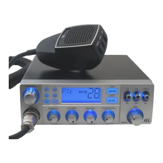
- Page 6 Technical Description 2-1. General Model CB-880 is an mobile type AM/FM radio transceiver for use of the Citizen Radio Service. Front Panel Controls ① LCD (Cannel and RX/TX Signal Level Indicator). ② Receiver Audio Control (With Power ON/OFF Control) Volume ③...
- Page 7 2-3. Frequency Table Channel Frequency (MHz) Channel Frequency (MHz) 26.965 27.215 26.975 27.225 26.985 27.235 27.005 27.245 27.015 27.255 27.025 27.265 27.035 27.275 27.055 27.285 27.065 27.295 27.075 27.305 27.085 27.315 27.105 27.325 27.115 27.335 27.125 27.345 27.135 27.355 27.155 27.365 27.165 27.375...
- Page 8 Semiconductors and Function 3-1. Transistor -------------------------------------------------------------------------------------------------------------------------------------------- Ref No. Description Manufacturer Function -------------------------------------------------------------------------------------------------------------------------------------------- Q101 KTC3880S RX Amplifier Q102 KTK211 1’st Mixer Q103 KTK211 1’st Mixer Q104 KRC101S RX Band1 Switching Q105 KRC101S RX Band2 Switching Q121 KRC110S Q122 KRC112S RX RSSI Level Control Q131 KTC3875S Squelch...
- Page 9 Q941 KRC111S Mute Q942 KRC112S TX B+ Mute at TX Mode Q951 KTA1241 Back Light LED Control Q952 KTA1241 Back Light LED Control Q953 KRC101S Back Light LED Control Q954 KRC101S Back Light LED Control Q961 KRC110S TX AF Mute at RX Mode Q962 KRC111S MIC AF Path at AM Mode...
- Page 10 Description of Frequency Determining and Stabilizing Circuit 4-1. Introduction The Frequencies for transmitter and receiver first local frequencies are all derived from a signal 4.5MHz crystal by means of a phase locked loop(PLL). The first local oscillator frequencies are 16.270MHz(CH1) to 16.710MHz(CH40). The second local frequency is fixed at 10.240MHz to generate second IF 455KHz.
- Page 11 Transmit CH 1 , 13.4825 MHz 26.965 MHz Transmit CH 40 , 13.7025 MHz 27.405 MHz Since all frequencies are obtained from the crystal controlled PLL oscillator, all outputs are coherent with the crystal oscillator frequency and matching the sample percentage accuracy. Note that the reference frequency of 5KHz(receiver) and 2.5KHz(transmitter) is obtained by dividing the 4.5MHz by 900 times and 1800 times See Table 1 for transmitter/receiver mode VCO frequencies.
- Page 12 Program Data & Frequency[Table 1] Frequency Channel [MHz] Fvco Fvco 26.965 3254 16.27 5393 13.4825 26.975 3256 16.28 13.4875 5395 26.985 3258 16.29 13.4925 5397 27.005 3262 16.31 13.5025 5401 27.015 3264 16.32 13.5075 5403 27.025 3266 16.33 13.5125 5405 27.035 3268 16.34...
- Page 13 4-3. Descriptions of Each Block 4-3-1. Introduction The synthesizer is implemented with the following components; PLL IC (IC301) X-TAL (X301) VCO, VARICAP DIODE (D301) IC1301 is CMOS LSI that includes most of PLL block. The Q301, L301, C311, C312, C313, C314, varicap diode D301 are clap oscillator circuit to operate as a VCO of the IC301.
- Page 14 4-3-7. Transmitter Doublers The output signal of Q302, L302 goes to an amplifier with tuning circuit Q701, L701, L702 which doubles incoming 13MHz signals. 4-3-8. Switching of Turning Capacitor in VCO The VCO circuit must tune with a wide range of frequencies 13.4825MHz ~ 13.7025MHz for transmitter and 16.27MHz ~16.71MHz for receiver.
- Page 15 4-5. Description of other Circuits 4-5-1. Transmitter RF Amplification RF carrier frequencies are obtained at the output of doublers amplifier Q701 and turning IFT coil L701, L702. The input of VCO frequencies 13MHz is selected at the doublers output, which creates the necessary 27MHz.
- Page 16 4-5-2. Receiver Overload protection is provided to receiver’s semiconductors by diode D101. These diodes have a little effect on the incoming signal from another CB station; they protect the receiver from stray transmitter energy. In the receiver mode of operation, Q923 transistor is turned on. Also bias voltage is applied to Q101, Q102, Q103, Q106.
- Page 17 Test Equipment Setup and Alignment Instructions General Section 5-1-1 Test Equipment Required • DC power supply(13.8V/3A) • DC Voltmeter or Oscilloscope • RF attenuator (30dB) 5-1-2 Alignment Procedure Step Setting Connection Adjuster Adjust for RX VCO voltage Adj. DC voltmeter to VCO L301 1.5~2.0 V DC Channel &...
- Page 18 Transmitter Section 5-2-1 Test Equipment Required • RF Power Meter • DC power supply(13.8V/3A) • 50 ohms load (non-inductive) • Spectrum analyzer • RF attenuator (30dB) • Frequency counter • Oscilloscope • Coupler • Audio generator • Modulation meter 5-2-2 Alignment Procedure Step Setting...
- Page 19 FM Deviation Adj. Connection the audio RV401 1.8KHz ~ Channel & Frequency : generator (set to 1 KHz)to the 2.0KHz 19CH, 27.185MHz microphone. MIC : Transmit Connect the modulation meter Function : FM Mode through the RF attenuator to CB/ANL Off/DX the ANT Connector.
- Page 20 Receiver Section 5-3-1 Test Equipment Required • Standard Signal Generator(SSG) • DC power supply(13.8V/3A) • AC Level Meter • Distortion Meter • Oscilloscope • SINAD Meter • 8 ohm Dummy Load 5-3-2 Alignment Procedure Step Setting Connection Adjuster Adjust for AM Audio Output Adj.
- Page 21 RX Signal Meter Adj. Connect RF Signal Generator RV572 Adjust for S-9 Channel & Frequency : to EXT-ANT Connector. on the signal 19CH, 27.185MHz Connect AC Level Meter and meter. MIC : Receive Distortion Meter and SINAD Function : FM Mode Meter across EXT SPK jack CB/ANL Off/DX with 8 ohm Dummy...
- Page 22 SECTION3 PART LIST Q'ty NAME & DESCRIPTION VENDOE CODE Location NO ITEM MAKER VENDOR ASS'Y REMARKS 880B * ELECT Parts COVER ASS'Y SPEAKER 77AR000-8P-4D29 ASAHI SPK201 ECO041217-03 WIRE HARNESS PH-2PIN TO OPEN UL1007 #26 L=200mm FINE FINE J204 ESCUTCHEON ASS'Y PCB VOLUME 1LAYER MULTI...
- Page 23 LCD DISPLAY SDMA2295B FOR TCB-880 SANTECH LCD801 SW801, SW802, SW803, SW804, SW805, SW TACT SKTS-1102A SEKWANG SEKWANG SW806, SW807, SW808 SW SLIIDE SKS-22021T SEKWANG SEKWANG SW101, SW102, SW201 RESONATOR 4.0MHz ZTA4.00MG D.TRON D.TRON X801 MAIN BODY ASS'Y CONNECTOR CH-239(A)-M SAMWOO...
- Page 24 CHIP RESISTOR 1/16W 5% T 1608 PHILIPS R101, R105, R106, R165, R236, R931 R138, R223, R406, R704, R915, R916, ECO050408-02 CHIP RESISTOR 4.7K 1/16W 5% T 1608 PHILIPS R962 ECO050418-02 R122, R139, R174, R176, R300, R303, ECO050715-01 CHIP RESISTOR 1/16W 5% T 1608 PHILIPS R409, R411, R415 ECO050715-04...
- Page 25 109 CHIP CERAMIC 1608 PHILIPS/SAMSUNG C317, C321 110 CHIP CERAMIC 68PF 1608 PHILIPS/SAMSUNG C97,C131, C732 111 CHIP CERAMIC 680PF 1608 PHILIPS/SAMSUNG C414 112 CHIP CERAMIC 82PF 1608 PHILIPS/SAMSUNG C406, C707 113 CHIP CERAMIC 1608 PHILIPS/SAMSUNG C326 114 CHIP TANTAL 2.2uF/16V A TYPE C301 ECO050418-02...
- Page 26 149 ELECT CAPACITOR 0.22UF KR1-16VR22MA 5X11 DONGXIANG C124 150 ELECT CAPACITOR 2.2UF KR1-16V2R2MA 5X11 DONGXIANG C741 151 ELECT CAPACITOR 22UF KR1-16V220MA 5X11 DONGXIANG C221 ECO050408-02 152 ELECT CAPACITOR 220UF KR1-16V221MA 5X11 DONGXIANG C210, C953, C954 153 ELECT CAPACITOR 33UF KR1-16V330MA 5X11 DONGXIANG C209 154 ELECT CAPACITOR...
- Page 27 VOL KNOB ABS (SILVER SPRAY) Bonso For Vol & Ch VOL KNOB ABS (BLACK COLOR) SQ KNOB ABS (SILVER SPRAY) Bonso For Sq, Rf, Mic gian, Q up/down SQ KNOB ABS (BLACK COLOR) ILLUMINATOR(VOL) ACRYL, CLEAR Bonso For Vol ILLUMINATOR(CH) ACRYL, CLEAR Bonso For Ch...
- Page 28 * ACCESSORY MIC ASS'Y Hankyung BRACKET SET ECO 050103-01 Hankyung Hankyung STUD BOLT ABS, M6*8L, BLACK Hankyung BRACKET(MIC) SUS304, 1.0t Hankyung PACKING RUBBER PACKING RUBBER Bonso SCREW Mach(+) M3*8L, Taptite, Black, BH SCREW TAP(+) 5*12L-1S, ZN PLATING, TH Bonso Bonso STAR WASHER-S M3, NI PLATING, B type Bonso...
- Page 29 SECTION4 MECHANICAL DISASSEMBLY...
- Page 30 PART NAME DESCRIPTION REMARK Upper cover SPC 0.8t Bottom cover SPC 0.8t Bracket (Set) SPC 1.6t Escutcheon Vol knob Sp knob illuminator (vol) Acryl illuminator (sq) Acryl Ring nut BsBm Nut for Mic connector Washer for Mic connector Key pad-6 Silicone Key pad-2 Silicone...
- Page 31 SECTION5 BOARD LAYOUT 5-1 Main PCB (Top side)
- Page 32 Main PCB (Bottom side)
- Page 33 5-2 Front PCB (Top side)
- Page 34 Front PCB (Bottom side)
- Page 35 5-3 LED PCB (Top side)
- Page 36 LED PCB (Bottom side)
- Page 37 5-4 Volume PCB...
- Page 38 5-5 MIC PCB...
- Page 39 SECTION6 BLOCK DIAGRAM...
- Page 40 SECTION7 SCHEMATIC...
Need help?
Do you have a question about the TCB-880 and is the answer not in the manual?
Questions and answers