
Related Manuals for Adleepower AP2G5-37


Summary of Contents for Adleepower AP2G5-37
-
Page 1: Instruction Manual
ADLEEPOWER INSTRUCTION MANUAL VARITORQUE INVERTER THANK YOU VERY MUCH FOR YOUR PURCHASE OF ADLEE INVERTER APxG5 SERIES. PLEASE READ THIS INSTRUCTION MANUAL BEFORE INSTALL THE INVERTER. -
Page 2: Table Of Contents
CONTENTS 1. PREFACE ○ ○ ○ ○ ○ ○ ○ ○ ○ ○ ○ ○ ○ ○ ○ ○ ○ ○ ○ ○ ○ ○ ○ ○ ○ ○ ○ ○ ○ ○ ○ ○ ○ ○ ○ ○ ○ ○... - Page 3 CONTENTS 7-2. Cautions for operating test ○ ○ ○ ○ ○ ○ ○ ○ ○ ○ ○ ○ ○ ○ ○ ○ ○ ○ ○ ○ ○ ○ ○ ○ ○ ○ 7-3. Setting for operation test ○ ○ ○ ○...
-
Page 4: Preface
1. PREFACE Thank you for purchasing ADLEEPOWER Varitorque Inverter APXG5 . Please read this manual thoroughly before install and operate APXG5 . This manual should be stored by the user of the APXG5 for ref- erence of maintenance and inspection. - Page 5 o i t r i f a t l a t l i r i t i c . s l i d i ※ ) . t ± a t l ± ) s l ) s l o i t ) .
-
Page 6: Acceptance Inspection And Precautions
i t a s " " t r s " " p o i t ON - OFF power source (NFB) l a t t i c i t a 1-1 Acceptance Inspection and Precautions During product manufacturing, packaging, and shipment have been standardised. -
Page 7: Nameplate Of Rating Details
1-2 Nameplate of rating details ADLEEPOWER MODEL AP2G5-110 VER V01 VER V 01 INPUT AC3 200/220V 50/60 Hz OUTPUT CURRENT SOFTWARE FUSE AMP 75A HARDWARE CAPACITY 17.6KVA (11KW/15HP) VERSION VARITORGUE INVERTER MODEL AP4G5-337 SOURCE AC3 380/440/460V 50/60 CAPACITY 6.5KVA(3.7KW/5HP) FUSE AMP... -
Page 8: Specifications
2. SPECIFICATION ± ± ψ ψ a t l ± ψ ψ a t l ( t n y t i a i r l o r i t a y t i o i t o i t i g i l a t i t t r i f... -
Page 9: Dimension
3. DIMENSION Unit : mm Fig 1... - Page 10 Unit : mm Fig 2 CHARGE ADLEEPOWER MODEL AP4G5-220 V ER V01 OUTPUT CURRENT CAPACITY 32.8KVA (22KW/30HP) 1. Do not conn ect power source t o 3. Do not conn ect powerfactor condensers af ter conf irm ation of condenser dis - out put termin als.
-
Page 11: External View And Component Names
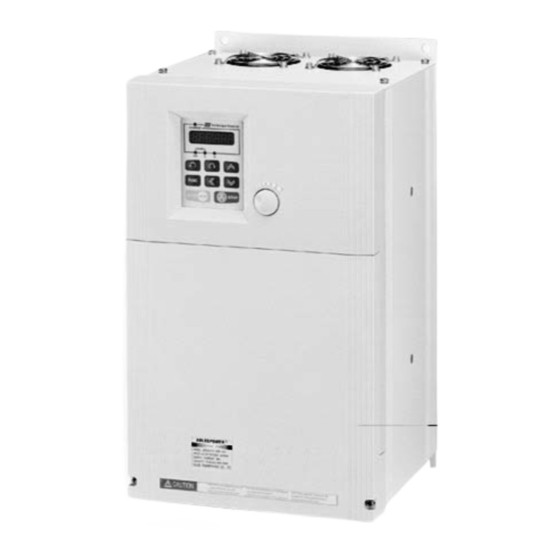
4. EXTERNAL VIEW AND COMPONENT NAMES 4-1 Parts( AP2G5-37 AP2G5-55 AP2G5-75 AP4G5-37 AP4G5-55 AP4G5-75 AP4G5-110) Pannel screw hole Operation keypad Plastic upper cover Vetilation hole Nameplate Pannel screw hole Plastic drive Iron plate Ventilation hole Lead wire hole Cooling fan... - Page 12 Plastic upper CHARGE cover Operation keypad ADLEEPOWER Nameplate Plastic drive M ODEL A P4G 5-220 VE R V 01 O UT PUT CURRENT CA PA CIT Y 32. 8K VA (22K W/ 30HP ) 1.Do no t co nne ct po wer source to 3.Do no t conn ect p owe rfa cto r co nde nsers...
-
Page 13: Keypad Explication
4-2 Keypad explication Series number Digital display CHARGE Digital display Series number CHARGE Varitorque Inverter FUNC STOP Keypad Keypad... -
Page 14: Installation
5. INSTALLATION 5-1 Installation environment To ensure proper performance and long operating lifetime, follow the recommendations below when choosing a location for installing the APxG5. Make sure the inverter is protected from the following condi- tions. Ambient temperature : -10 ~ 45 and a good venti- ℃... -
Page 15: Description Of Terminals And Wiring
6. DESCRIPTION OF TERMINALS AND WIRING 6-1 Wiring diagram External braking resistor (Note) MCCB Input power Motor Forward run / stop Reverse run / stop Ground Less than 0.1 Ω Multistage speed 1 Multistage speed 2 Multi function 1 Analog source Multi function 2 Analog input IN Reset... -
Page 16: Main Circuit Connection Diagram And Wiring
6-2 Main circuit connection diagram and wiring POWER SUPPLY MOTOR Ground Power input External braking Ground resistor (★Note) Motor Ω ± ψ ± ψ ± i t a a t l t s i ★ NOTE : Remove the internal braking resistor in P1 and P2 before connect the external braking resistor to avoid the damage. -
Page 17: Connection Of External Control Signals
6-3 Connection of external control signals Analog Input External Control Circuit Fault Output 10V GND FA1 FA2 COM FWD REV CF1 CF2 FT1 FT2 RST RUN ARR MET FLA FLC FLB Fault Relay Contact rating : 1A 240VAC 1A 30VDC VR5KΩ... - Page 18 i t l i t l...
-
Page 19: Main Circuit's Breaker And Magnetic Contactor For Wiring
Note 1 : The control board “J14” for encoder power source select +5V or 15V. (Factory for +5V) 6-5 Main circuit’s breaker and magnetic contactor for wiring y t i t i u c i t For safety consideration, please install molded-case circuit breaker (MCCB) or magnetic contactor (MC) between AC power source and the inverter AC power input terminals RST. -
Page 20: Cautionary Points For Wiring
2. If the total wiring distance between inverter and motor is excessively long and the inverter carrier frequency (main transistor switching frequency) is high, harmonic leakage current from the cable will adversely to affect the inverter and peripheral devices. If the wiring distance between in- verter and motor is long, reduce frequency can be set by constant F20. - Page 21 B. Control circuit wiring signal 1. Separate control circuit wires from power cables to pre- vent erroneous operation caused by noise interference. 2. Use shielded wires for control circuit wires. 3. To wire the external control signals, please refer to 6-3. C.
-
Page 22: Operation Test
7. OPERATION TEST 7-1 Pre-check points All wiring are connected correctly. The motor power output is fit inverter’s specification. Wire clips or screws are not left in the unit. Screw-type terminals are screwed tightly. The cover of inverter’s is fixed tightly. 7-2 Cautions for operating test Avoid damaging the machine, please do the operation test by no load. -
Page 23: Setting For Operation Test
7-3 Setting for operation test (A) Operate by keypad The diagram below shows a operational pattern : Forward STOP 60Hz Reverse Power 60Hz STOP STOP Forward Reverse Forward Reverse t p i t i a □□□ r i f... - Page 24 i r c r i f r i f...
- Page 25 (B) Operation external terminal signal The diagram below shows a operational pattern : Power REV off FWD on FWD off Turn VR to REV on Max. speed i r c □□□ r i f...
- Page 26 r i f r i f r i f F " " " " V " " F " " " " " " V " " " " V " "...
-
Page 27: Control Mode Setting
8. CONTROL MODE SETTING 8-1 Control mode selection APxG5 provides 5 different control modes : 1. v/f open loop control. 2. v/f close loop control with PG (pulse generator). 3. v/f sensorless close loop control. 4. Current vector with PG close loop control. 5. -
Page 28: Control Mode Characteristics
8-2 Control mode characteristics - i t - i t... -
Page 29: Control Mode Change
8-3 Control mode change Example of changing V/F open loop control to vector close loop control with PG. t p i t i a □□□ . t i l l i d i l . t r 8-4 Motor parameter Auto tunning procedure "... - Page 30 [Auto inspection of operation procedure] . y r i t o . e l i t a . y l l o i t o i t i r c □□□ i t t y l t " " 0 "...
- Page 31 [Mechanical inspection of operation procedure] . y r i t o . e l l l a o i t o i t . y l l o i t o i t t p i t i a □□□ i t t t i a y l t...
-
Page 32: Parameter Explanations
9. PARAMETER EXPLANATIONS 9-1 Parameter’s lists (1) t i n ± n i l a t l n i l r ( t t s i t s i f l e l s ( t / t i a t l... - Page 33 9-1 Parameter’s lists (2) o i t t i n i t t o i t i t t / l a o i t a t l i n i...
- Page 34 9-1 Parameter’s lists (3) o i t t i n i t t s f f o i t o i t o i t o i t o i t...
- Page 35 9-1 Parameter’s lists (4) o i t t i n i t t o i t o i t o i t o i t o i t o i t o i t o i t o i t o i t o i t - i t l...
- Page 36 9-1 Parameter’s lists (5) o i t t i n i t t - i t l o i t i t t a t l a t l a t l a t l a t l c i f a t l a t l e l r...
- Page 37 9-1 Parameter’s lists (6) t i n a t l z i t a t l a t l p i l t i n...
- Page 38 9-1 Parameter’s lists (7) o i t t i n i t t o i t y t i i t t i t t t l u t - i o i t t n i i t t t n i t n i t n i...
- Page 39 9-1 Parameter’s lists (8) t i n i t t t n i i t t t n i i t t t n i i t t t n i i t t t n i i t t t n i i t t t n i...
- Page 40 9-1 Parameter’s lists (9) r i f i t i...
-
Page 41: Functional Parameters
9-2 Functional Parameters To consider users’ understanding and to make ADLEE vector inverter work more efficiently, this chapter will introduce the func- tions as a whole and will divide them into 9 sub-parameters. In most application, users can accomplish the installation before start-up, based on the functions related from the following param- eters. -
Page 42: Basic Parameters
9-2-2 Basic parameters i n i a t l a t l a t l a t l a t l 9-2-3 Operating method parameters - i t l... - Page 43 Follow 9-2-3 parameter - i t l c i f a t l 9-2-4 Input / output function parameters - i t l l s ( t / t i - i t l a t l s f f i t l y t i i g i...
- Page 44 9-2-5 Multi-step speed and auto tunning parameters o i t o i t i t t t n i i t t t n i i t t t n i i t t t n i i t t t n i t n i i t t...
- Page 45 Follow by 9-2-5 parameter i t t t n i t n i i t t i t t 9-2-6 Protection parameters i h t z i t a t l a t l i l t r i f l a t 9-2-7 Motor parameters n i l...
- Page 46 Follow by 9-2-7 parameter f l e t s i t s i 9-2-8 Special parameters a t l a t l a t l p i l t l u i t - i t n i 9-2-9 PI control parameters...
-
Page 47: Parameter Descriptions
9-3 Parameter descriptions 9-3-1 Motor nameplate description(F00~F06) Example of 380V 5HP motor nameplate ADLEEPOWER Poles POLES TYPE 5043 Horse power Rated frequency OUTPUT Rated line voltage (rms) VOLTS BEARING 380V Rated line current(rms) DATE AMP.S 8.1A Rated R.P.M SERIAL NO. - Page 48 9-3-2 Motor parameter(F07~F12) Motor parameter can be either-manually assigned, or values are available to be identified by the Auto turnning process. Auto tuning function is setting by F23. i r c × √ t s i π × × × t s i ×...
- Page 49 o i t o i t a t l a t l 9-3-4 PWM parameter(F19~F22) o i t o i t i t t c i f , t n c i f i t t i t t High carrier Low carrier frequency frequency...
- Page 50 o i t o i t c i r i t t . l o h t i . l o h t i . l o . l o ※ h t i n i t ※ h t i n i t 9-3-6 Operation mode parameter(F24~F31) o i t...
- Page 51 t p i t i g n i l , l a . y l l l i . t i (HZ) (HZ) Search motor stop stop speed command command when F27=1 when F27=0 command Acceleration time F28=0 (U.V.W output signal) Deceleration time F28=1 F28=2...
- Page 52 o i t o i t i t t i t t (HZ) setting range 1 2 3 4 5 6 7 8 9 0 1 2 3 4 5 6 7 8 9 0 1 1 2 3 4 5 6 7 8 9 0 1 2 3 4 5 6 7 8 9 0 1 1 2 3 4 5 6 7 8 9 0 1 2 3 4 5 6 7 8 9 0 1 1 2 3 4 5 6 7 8 9 0 1 2 3 4 5 6 7 8 9 0 1 1 2 3 4 5 6 7 8 9 0 1 2 3 4 5 6 7 8 9 0 1...
- Page 53 o i t o i t i t a " l " 2 o i t i t t i t t i t t i t s . t i i t t i t t 400HZ setting range i t t i t s .
- Page 54 o i t o i t Frequency setting 30HZ 0.5HZ TIME Running TIME command 9-3-8 Speed mode and multi-speed(F36~F47) i t l & Operation signal Output frequency speed 1 speed 1 speed 4 speed 2 speed 3...
- Page 55 o i t o i t i t t o i t h t i . l a i t t i t t Frequency setting TIME Jogging TIME command y r t n i t When F46=400 When F46=200 VR adjust to Max.
- Page 56 o i t o i t s f f o i t n i t When F47=5HZ, the real output curve constantly more then input command 5HZ Analog input signal (IN, FA1, FA2) When F47=-5HZ, the real output curve -5HZ constantly more than input command 5HZ o i t...
- Page 57 o i t o i t o i t . t n i t t i t t i h t o i t . t n i t t i t t jump 1 jump 3 jump 2 Fset 9-3-10 Acceleration/Deceleration control parameter(F52~F68) o i t o i t...
- Page 58 o i t o i t when F54=50% when F54=100% T(sec) T(sec) o i t o i t . e t l a t s ' t o i t o i t l a t o i t o i t .
- Page 59 o i t o i t o i t o i t o i t o i t 9-3-11 Digital terminal input(F69~F73) o i t o i t - i t l o i t - i t l o i t i f e - i t l o i t...
- Page 60 o i t o i t n i t i t c i t c i t c o i t o i t o i t o i t a t l . y l a t l . y l a t l o i t , y l...
-
Page 61: Inverter Output
o i t o i t a t l o i t a t l o i t a t l a t l c r i t i u o i t i t t FWD(REV)command Stop command Inverter output General wiring Setting F24=1 (terminal control) FWD(REV)command... - Page 62 t p i c t i when FT1 & COM are short circuit. The inverter will stop. FT2=7(Thermistor) NTC/PTC ★ J5(FT2) Resistance < 1K Ω , STOP Ω Resistance > 1K , STOP 5-10HP Resistance < 1K Ω , STOP Ω...
- Page 63 o i t o i t +10% Setting frequency1 -10% +10% Setting frequency2 -10% Output ARR Terminal Open collect wave form × o i t 10K Ω 1 cycle...
- Page 64 9-3-12 Analog terminal input(F74~F75) o i t o i t - i t l o i t , l a i t t o i t o i t - i t l o i t i t t o i t .
- Page 65 9-3-13 Voltage/Frequency limit and flux parameter(F76~F82) o i t o i t a t l a t l i t t a t l a t l t i n o i t F " " 0 a t l t a l ×...
- Page 66 o i t o i t F81=0 ( for constant torque use ) F81=-1 ~ -10 ( for reduce torque use ) ※ c i f o i t u l f o i t t I . c i f l l i y t i i t t...
- Page 67 o i t o i t a t l o i t i t t i t t c i t . y l 9-3-15 Speed control bandwidth(F85~F91) o i t o i t . n i . n i .
- Page 68 o i t o i t . l o i t t . l o Speed F92=0 Torque F92=1 Time Time i t t . t u i t t o i t e l i o i t i t t o i t , t u , l o...
- Page 69 o i t o i t Torque When F97=1 that is actual output curve Analog input signal (IN) When F97=-1 that is actual output curve Time 9-3-17 Current mode control parameter(F98~F100) o i t o i t i t e o i t i f e i t e...
- Page 70 o i t o i t > real speed real speed < real speed adjust from 100 adjust from 100 9-3-19 Keypad display setting parameter(F104~F105) o i t o i t o l l o i t o i t i t t i t s p i l...
- Page 71 9-3-20 Analog signal output display setting parameter (F106~F111) o i t o i t o i t i t t i t s p i l a t l t i l i t e o i t a t l a t l t i l i t e...
- Page 72 o i t o i t F107=1, R.P.M=0 Voltage its output voltage is 2.5V Anode pole 2.5V Negative pole Time i t t s ' r a t l ÷ ∵ ∴ × s ' r a t l l u f .
- Page 73 o i t o i t . e l t n i i t t × a t l × × o i t o i t t n i i t t h t i 9-3-22 Error records(F155~F159)
- Page 74 i r c ' s t r i f r i f i h t i h t i h t Error F155 F156 F158 F157 Loss occur 9-3-23 Over load(F160~F161) o i t o i t o l r i t s o l r o i t...
- Page 75 o i t o i t Current (A) F160 Reach F161 time limit Time (T) F160 start to count 9-3-24 Stall prevention(F162~F164) o i t o i t l a t o i t . e l i t t .
- Page 76 i r c Current F164 Output HZ Constant frequency Time ( / ) ( / ) 1 " " 0 9-3-25 Other item(F176~F180) o i t o i t i n I a i t s ' r i t t i n i a i t i n i...
- Page 77 ※ 1 " , " l l i Start CPU ROM Missing Setting 0~175 parameter to CPU Finish F177 setting on 1 , the internal parameter of CPU will be record c i f y f i r i f n i l...
-
Page 78: Maintenance And Failures Eliminate
10. MAINTENANCE AND FAILURE ELIMINATE Maintenance and inspect regularly, which can make your inverter keep working for long period in right status. 10-1 Attention points of maintenance and inspection 1. During the maintenance and inspection, please turn off the power supply of your inverter (R.S.T.) 2. -
Page 79: Trouble Shooting
10-3 Trouble shooting In case of the inverter failure cannot be remove by following methods, please contact with your agent or factory. o i t o i t a t l a t l e l i - t r r i c . - Page 80 o i t o i t a t l . y t o i t h t i i t t a t l u l i , r i o i t n i t i f i o i t / t i l u l i i t t...
- Page 81 o i t o i t o i t u l i n i t o t t i t t i a t , r i . r i g i l . r i g i l i a f r u l , y l l y l t...
-
Page 82: Application
11. APPLICATION Example 1 : Use 2 external variable resistor for multistage speed command input. DESCRIPTION : F24 = 1 (External terminal control) F25 = 1 (Select speeds by external digital terminals) F74 = 1 (Set FA1 for 1 speed input terminal) F75 = 2 (Set FA2 for 2 speed input terminal) - Page 83 Example 2 : Normal / Jog operation DESCRIPTION : F36 = Master speed ; User setting F45 = Jog speed ; User setting F24 = 1 ; Terminal command (For external) F69 = 1 ; Define FT1 terminal=JOG (Foward) function FT1(J0G) S1 = FWD SW S2 = REV SW...
- Page 84 Example 3 : Basic external control setup DESCRIPTION : F108 = 60 ; See Maximum value on the meter F25 = 3 ; External analog signal 0~10V F24 = 1 ; External command 10V GND WHITE BLACK START 10V/1mA Full scale...
- Page 85 Example 4 : Alarm output DESCRIPTION : F24 = 1 ; External command 18(A) + ALARM START STOP 30Vdc 19(C) 20(B) - 7(COM) 8(FWD)
- Page 86 Example 5 : Pulse generator usage DESCRIPTION : F71 = 1 F73 = 24 (No. of pulse/rev) (1) Press machine (2) Constant distance RUN/STOP conveyor...
- Page 87 Example 6 : Rolling machine usage VCC FAI GND VCC FAI GND s f f Relation : B Motor = A Motor + 5HZ...
-
Page 88: Appendix 1 Select Right Inverter
Appendix 1 : Select right inverter Inverter capacity check method t p i t c i i v ( t a l i t s i t s n i l i t s i t i t i t - i t - i ( t y t i... - Page 89 y t i i t s ※ ※ ※ ※ ※ ※ ※ ※ ※ ※ ※ ※ ※ ※ ※ ※ ※ ※...
-
Page 90: Appendix 2 Inverter Capacity Calculation Formula
Appendix 2 : Inverter capacity calculation formula Inverter capacity requirment for multidriving i r c K Pm nT + nS ( kS - 1 ) η ψ y t i = Pc1 1 + ( nS / nT )( ks - 1 ) ≦... - Page 91 i r c K Pm nT + nS ( kS - 1 ) ψ η 1 + ( nS / nT )( ks - 1 ) ≦ Inverter capacity [KVA] nT lm 1 + ( nS / nT )( kS - 1) Inverter capacity [A] ≦...
-
Page 92: Appendix 3 Motor Selection Reminder
Appendix 3 : Motor selection reminder Standard Motor Please pay attention to the following when using inverter to drive standard motor(3 phase induction motor) : 1. When using inverter to drive standard motor, its power loss is higher than using commercial power. 2. -
Page 93: Appendix 4 Remote Operator F306
Appendix 4 : Remote operator F306 For cable connect 63.5 63.5 63.5 63.5 UNIT : mm Options Please order “R” models for remote control inverters as APxG5-37R, APxG5-55R and APxG5-75R etc., and mark the extension cord length as above table shown. ★... -
Page 94: Appendix 5 Optional Braking Resistor
Appendix 5 : Optional braking resistor Braking resistor value, are refered to the following table and re- sistor value should be higher than list below. When connect ex- ternal braking resistor, the internal braking resistor must be re- leased. Please see the diagram. (P1.P2 terminal wiring) Braking resistor value table UNIT : Ω... -
Page 95: Appendix 6 Version
Appendix 6 : Version Software Hardware Version... - Page 96 MEMO...
- Page 97 MEMO...
- Page 98 Printed in Taiwan 2004 API. 1ST Edition ADLEE POWERTRONIC CO., LTD. TAIWAN HEAD OFFICE CHINA GUANG DONG OFFICE Tel No : 886-4-25622651 Tel No : 86-757-26656498 Fax No : 886-4-25628289 E-mail : guandongo@adlee.com E-mail : webmaster@adlee.com URL : http://www.adlee.com CHINA SHANGHAI OFFICE CANADA OFFICE Tel No : 86-21-64843529 Tel No : 1-604-324-6578...
Need help?
Do you have a question about the AP2G5-37 and is the answer not in the manual?
Questions and answers