Table of Contents
Advertisement
Quick Links
All manuals and user guides at all-guides.com
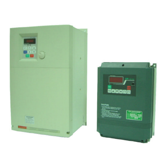
INSTRUCTION MANUAL
GENERAL-PURPOSE
AP2G3-137~AP2G3-1185
AP2G3-337~AP2G3-3220
AP4G3-337~AP4G3-3220
THANK YOU VERY MUCH FOR YOUR PURCHASE
OF ADLEE INVERTER APxG3 SERIES.
PLEASE READ THIS INSTRUCTION MANUAL
BEFORE INSTALLATION OF THE INVERTER.
ADLEEPOWER
INVERTER
R
Advertisement
Table of Contents

Related Manuals for Adleepower AP2G3-137


Summary of Contents for Adleepower AP2G3-137
- Page 1 All manuals and user guides at all-guides.com ADLEEPOWER INSTRUCTION MANUAL GENERAL-PURPOSE INVERTER AP2G3-137~AP2G3-1185 AP2G3-337~AP2G3-3220 AP4G3-337~AP4G3-3220 THANK YOU VERY MUCH FOR YOUR PURCHASE OF ADLEE INVERTER APxG3 SERIES. PLEASE READ THIS INSTRUCTION MANUAL BEFORE INSTALLATION OF THE INVERTER.
-
Page 2: Table Of Contents
All manuals and user guides at all-guides.com CONTENTS 1. RECEIVING 2. SPECIFICATIONS 3. DIMENSION DRAWINGS 4. INSTALLATION 5. DESCRIPTION OF TERMINALS 6. DIGITAL OPERATION PANEL 7. FUNCTIONS DESCRIPTION 8. PROTECTIVE FUNCTIION 9. PRECAUTIONS 10. TROUBLESHOOTING 11. APPLICATION 12. INVERTER SELECTION 13. -
Page 3: Receiving
All manuals and user guides at all-guides.com 1. RECEIVING Befor installation and wiring, check to see : (1) No damage is found on each product after shipping. (2) The product is as ordered (check the nameplate, voltage and fre- quency). (3) A set of inverter unit and instruction manual is contained in the package. -
Page 4: Specifications
All manuals and user guides at all-guides.com 2. SPECIFICATIONS Model AP2G3 Voltage 1φ 220VAC ± 10% 3φ 220VAC ± 10% Model No 1110 1150 1185 3110 3150 3185 3220 Input Frequency 50HZ/60HZ ±5% Output Voltage 3φ 220VAC Output Frequency 0.5 ~ 400HZ Output Rated current (A) Capacity (KVA) - Page 5 All manuals and user guides at all-guides.com Model AP4G3 Voltage 3φ 380/440VAC ±10% Model No 3110 3150 3185 3220 Input Frequency 50HZ/60HZ ±5% Output Voltage 3φ 380/440VAC Output Frequency 0.5 ~ 400HZ Output 16.5 Rated current (A) Capacity (KVA) 12.6 17.6 23.6 Largest motor...
-
Page 6: Dimension Drawings
All manuals and user guides at all-guides.com 3. DIMENSION DRAWINGS Unit : mm ( AP2G3-137 AP2G3-155 AP2G3-175 ) ( AP2G3-337 AP2G3-355 AP2G3-375 ) ( AP4G3-337 AP4G3-355 AP4G3-375 AP4G3-3110 ) Fig 1... - Page 7 All manuals and user guides at all-guides.com Unit : mm ( AP2G3-1110 AP2G3-1150 AP2G3-1185 ) ( AP2G3-3110 AP2G3-3150 AP2G3-3185 AP2G3-3220 ) ( AP4G3-3150 AP4G3-3185 AP4G3-3220 ) Fig 2...
-
Page 8: Installation
All manuals and user guides at all-guides.com 4. INSTALLATION Inadequate environment around installation site and installation surface can result in damage to the inverter. Before operating the APxG3 series inverter, please check the following points : (1) Avoid high temperature, high humidity, easy-to-dew ambient envi- ronment. - Page 9 All manuals and user guides at all-guides.com AIR FLOW...
-
Page 10: Description Of Terminals
All manuals and user guides at all-guides.com 5. DESCRIPTION OF TERMINALS (1) Main circuit connection diagram P P R AP2G3-137~175 AP2G3-337~375 AP4G3-337~3110 Ground Power source Ground Braking resistor (★ Note ) P 2 P 1 U AP2G3-1110~1185 AP2G3-3110~3220 AP4G3-3150~3220 Ground... - Page 11 All manuals and user guides at all-guides.com (2) Description of hardware setting AP2G3-137~AP2G3-175, AP2G3-337~AP2G3-375, AP4G3-337~AP4G3-3110 RS485 GND FA1 FA2 H COMFWD REV CF1 CF2 FT1 FT2 RST ARR/RUN AP2G3-1110~AP2G3-1185, AP2G3-3110~AP2G3-3220, AP4G3-3150~AP4G3-3220 RS485 10V GND FA1 FA2 FG1 H COMFWD REV CF1 CF2 FT1 FT2 RST...
- Page 12 All manuals and user guides at all-guides.com (3) Analog signal switch setting AP2G3-137~175, AP2G3-337~375, AP4G3-337~3110 SIGNAL 0 - 10V 1 2 3 4 1 2 3 4 0 - 5V 1 2 3 4 1 2 3 4 4 - 20mA ★...
- Page 13 All manuals and user guides at all-guides.com AP2G3-1110~1185, AP2G3-3110~3220, AP4G3-3150~3220 SIGNAL Keypad VR/F306 Keypad VR 1 2 3 4 5 6 F306 1 2 3 4 5 6 Error setting 1 2 3 4 5 6 Error setting 1 2 3 4 5 6 SIGNAL 0 - 10V 1 2 3 4 5 6...
- Page 14 2 and 3 short circuit : Analog output. (0~10VDC refer to 0~CD14) 3. JP3 : Pannel VR and F306 VR selection AP2G3-137~AP2G3-175, AP2G3-337~AP2G3-375, AP4G3-337~AP4G3-3110 1 and 2 short circuit : Pannel VR. 2 and 3 short circuit : F306 VR.
- Page 15 MA MB ARR/RUN Fault Relay Ground Relay Contact rating : ARR/RUN 1A 240VAC VR5KB 1A 30VDC AP2G3-137~175、 AP2G3-337~375、 AP4G3-337~3110 10V GND FA1 FA2 FG1 REV CF1 CF2 FT1 FT2 RST MET MA ARR/RUN Fault Relay Ground Relay VR5KB Contact rating :...
- Page 16 All manuals and user guides at all-guides.com Control circuit terminal Symbol Terminal Description Ground terminal 1 Grounding Analog source Power source +10V of analog terminals Analog common terminal Common terminal of free analog terminals Free analog terminal 1 See functions description (CD44) Free analog terminal 2 See functions description (CD45) Ref.
- Page 17 All manuals and user guides at all-guides.com (6) WIRING 6-1 Wiring of main circuit ∮ 1.AP2G3 1 power source THRY APxG3-Series terminal connect L1/R and L2/S. L1/R ∮ ∮ 2.AP2G3 3 and AP4G3 3 POWER SOURCE L2/S L3/T power source terminal connect L1/R, L2/S and L3/T.
- Page 18 All manuals and user guides at all-guides.com 6-3 Surge absorber In order to prevent malfunction, provide the surge absorber on the coils of the electromagnetic contactors, relays and other devices which are to be used adjacent of the inverter. 6-4 Cable size and length If the inverter is connected to a distant motor (especially when low frequency is output), motor torque decreases because of voltage drop in the cable.
- Page 19 All manuals and user guides at all-guides.com 6-5 Wiring and cautionary points A. Main circuit 1. Don t connect the cables of the power supply side (L1/R,L2/S,L3/ ’ T) to the U, V and W output terminals for the motor. 2.
-
Page 20: Digital Operation Panel
All manuals and user guides at all-guides.com 6. DIGITAL OPERATION PANEL Model AP-G3 DSP Indication Digital Indication SMART INVERTER LED Operating Indication FUNC PROG STOP Model Indication LED Operating FW D Indication FREQ. SET Operation key Key function Description FWD RUN Forward run Commands forward run REV RUN... -
Page 21: Functions Description
All manuals and user guides at all-guides.com 7. FUNCTIONS DESCRIPTION DISPLAY FUNCTION DEFAULT VALUE CODE 60.00HZ ☆ CD00 First speed setting 50.00HZ CD01 Parameter lock CD02 Acceleration time 1 10.0Sec CD03 Deceleration time 1 10.0Sec CD04 Jogging frequency 5.00HZ CD05 Start frequency 0.50HZ CD06... - Page 22 All manuals and user guides at all-guides.com DISPLAY FUNCTION DEFAULT VALUE CODE 60.00HZ ☆ CD17 1st Maximum voltage frequency 50.00HZ CD18 V/F pattern setting CD19 DC braking time 1.0Sec CD20 DC braking power CD21 Torque boost 0.0% CD22 Second speed setting 20.00HZ CD23 Third speed setting...
- Page 23 All manuals and user guides at all-guides.com DISPLAY FUNCTION DEFAULT VALUE CODE CD38 Errors record 2 NONE CD39 Errors record 3 NONE CD40 Clear errors record CD41 HZ / RPM / AMP Display CD42 FT1 Multi-Function Terminal 1 CD43 FT2 Multi-Function Terminal 2 CD44 FA1 Free Analog Terminal 1 CD45...
- Page 24 All manuals and user guides at all-guides.com DISPLAY FUNCTION DEFAULT VALUE CODE CD60 2st step timer 0.00 CD61 3st step timer 0.00 CD62 4st step timer 0.00 CD63 5st step timer 0.00 CD64 Timer unit selector CD65 Stall prevention CD66 Overload current stall prevention 170.0% CD67...
- Page 25 All manuals and user guides at all-guides.com Communication address description DISPLAY FUNCTION UNIT CODE Speed command for RS485 Frequency data output for RS485 0.01HZ Current data output for RS485 0.1A Fault code for RS485 Different initial set value for F50.0 : 50HZ power region and ☆...
- Page 26 All manuals and user guides at all-guides.com 7-1. Function setting Before starting test run, check carefully the following points : (1) Be sure to connect the power supply to L1/R, L2/S, L3/T (input terminals) and the motor to U.V.W. (output terminals). (Wrong connections will damage the inverter.) (2) Check that the input power supply is 220VAC 10%, 50/60HZ...
- Page 27 All manuals and user guides at all-guides.com Operation 1-1. Pannel Action : (a) Press for forward / reverse operation. Speed : (a) Using to change motor speed with 1HZ increment step. or to select the digit for quick setting and confirm by PROG Standby : (a) Press back to standby mode after trip or function...
- Page 28 All manuals and user guides at all-guides.com Setting Range 0.00 ~ 400.00HZ First speed setting 60HZ region 60.00HZ CD00 50HZ region 50.00HZ Press key for increase or decrease the speed with 1HZ increment . Press key to select the digit for quick setting. Press to save the setting value.
- Page 29 All manuals and user guides at all-guides.com Deceleration time 1 Setting Range 0.1 ~ 6000.0Sec Default Value 10.0Sec CD03 CD03 value corresponds to the 60HZ time of deceleration from 50/60HZ to 0. 6000 TIME(Sec) Jogging frequency Setting Range 0.00 ~ 400.00HZ Default Value 5.00HZ CD04...
- Page 30 All manuals and user guides at all-guides.com Jog mode Setting Range 0 or 1 Default Value CD06 0 : Normal 1 : Jog Mode 1. Set jogging operation from key panel & LED blinking in JOG mode. Setting Range 30.00 ~ 400.00HZ Analog output gain 60HZ region 120.00HZ...
- Page 31 All manuals and user guides at all-guides.com Search speed Setting Range 0 or 1 function Default Value CD09 0 : Normal operation. 1 : Search motor speed when start. (HZ) (HZ) Start frequency Time(sec) Time(sec) stop stop CD09=1 CD09=0 Analog / Digtal frequency Setting Range 0 or 1...
- Page 32 All manuals and user guides at all-guides.com Dynamic brake / Free running Setting Range 0 or 1 Default Value CD11 FWD/REV 0 : Activates dynamic brake Command time function when deceleration. CD11=0 1 : Output cut off when accept time a stop command to be free CD11=1 running.
- Page 33 All manuals and user guides at all-guides.com Maximum Setting Range 0.50 ~ 400.00HZ frequency limit 60HZ region 120.00HZ CD14 50HZ region 50.00HZ 400HZ 0.5HZ Speed command Minimum frequency Setting Range 0.00 ~ 400.00HZ limit Default Value 0.00HZ CD15 400HZ Speed command Frequency display Setting Range 0.01 ~ 500...
- Page 34 All manuals and user guides at all-guides.com When RPM > 9999 display for over range warning. On this condition. Setting CD41=1 for display shown RPM. Scale for various motors Synchronous speed Scale Pole setting 50HZ 60HZ 3000 3600 1500 1800 1000 1200 1st Maximum...
- Page 35 All manuals and user guides at all-guides.com V/F pattern setting Setting Range 0 ~ 2 Default Value CD18 Volt 0 = Constant torque curve 100% 1 = Reduce torque curve F 2 = Reduce torque curve F 400(Hz) DC braking time Setting Range 0.0 ~ 25.0Sec Default Value...
- Page 36 All manuals and user guides at all-guides.com Torque boost Setting Range 0.0 ~ 25.0% Default Value 0.0% CD21 Torque boosting is used to compensate the torque lost due to stator resistance. Over boosting will cause over current and high acoustic noise.
- Page 37 All manuals and user guides at all-guides.com Terminal Operation Signal order CF1 CF2 Terminal CF1 Terminal CF2 SPEED SPEED - 1 OFF OFF Output frequency SPEED - 2 ON Speed 1 Speed 1 SPEED - 3 OFF ON Speed 2 Speed 4 Speed 3 SPEED - 4 ON...
- Page 38 All manuals and user guides at all-guides.com Carrier frequency Setting Range 1.0 ~ 16.0K Default Value 16.0K CD27 Increase the carrier frequency would reduce motor noise but efficiency might be decreased. Reduce the carrier frequency would increase noise and reduce motor current, than gain better efficiency.
- Page 39 All manuals and user guides at all-guides.com Frequency jump 2 Setting Range 0.00 ~ 400.00HZ Default Value 0.00HZ CD30 Frequency jump 3 Setting Range 0.00 ~ 400.00HZ Default Value 0.00HZ CD31 JUMP 1 JUMP 3 JUMP 2 Speed command Jump range Setting Range 0.50 ~ 3.00HZ Default Value...
- Page 40 All manuals and user guides at all-guides.com Frequency Setting Range 0.00 ~ 400.00HZ reference bias Default Value 0.00 CD33 Move Frequency bias with 100% same gradient. Frequency in the range of “- “ bias, motor is stop. +Bias Analog input -Bias Freq.
- Page 41 All manuals and user guides at all-guides.com The latest error record CD36 Error record 1 CD37 Error record 2 CD38 Error record 3 CD39 Errors record flow-chart when Error occur. The new content will shift the other contents to one higher CD code and the highest one will be dropped.
- Page 42 All manuals and user guides at all-guides.com HZ/RPM/AMP Setting Range 0 ~ 2 Display Default Value CD41 0 = HZ Display 1 = RPM Display 2 = Current Display Setting corrent scale CD16 for R.P.M. display shown. FT1 Multi-Function Setting Range 0 ~ 15 Terminal 1 Default Value...
- Page 43 All manuals and user guides at all-guides.com Application circuit with latch function STOP FWD STOP R and CONTROL POWER not necessary Remark: STOP command entry from control terminal 5 FT1 or 6 FT2, and Control power set CD42(FT1)=5 or CD43(FT2)=5 before operation.
- Page 44 All manuals and user guides at all-guides.com Free analog terminal 1 Setting Range 0 ~ 15 Default Value CD44 Refer to CD45 table. Free analog Setting Range 0 ~ 15 terminal 2 Default Value CD45 Setting NO. 11 to use application of example 03. Setting Range Function Min-------Max...
- Page 45 All manuals and user guides at all-guides.com SPEED CF3 CF2 CF1 5th speed setting 1th speed setting OFF OFF OFF CD47 2th speed setting OFF OFF ON 3th speed setting OFF ON 6th speed setting 4th speed setting OFF ON CD48 5th speed setting ON OFF OFF...
- Page 46 All manuals and user guides at all-guides.com Setting Range F50.0/F60.0 Version selector 60HZ region F60.0 CD52 50HZ region F50.0 Select function CD52, then use UP/Down key to select F50.0/F60.0 Version. Press to save it. System will return to the factory PROG setting and go into waiting mode..
- Page 47 All manuals and user guides at all-guides.com 4 ~ 20 mA speed command Setting Range 0 ~ 3 Default Value CD54 This function only effects in CD44(CD45)=8,9,10,13. Set FA1(FA2) for current signal (4-20mA). 0 : No current signal application Fmax 1 : Current signal in terminal FA1 2 : Current signal in terminal FA2 3 : FA1 &...
- Page 48 All manuals and user guides at all-guides.com 2nd Maximum Voltage frequency Setting Range 25.00 ~ 400.00HZ Default Value 60.00HZ CD56 Set CD42(CD43)=7 define FT1(FT2) terminal for hardware V/F curve switcher. Open : select the 1st V/F curve preset in CD17 Close : select the 2nd V/F curve preset in CD56 100% 1 V/F...
- Page 49 All manuals and user guides at all-guides.com CD58 Auto running mode Speed with timing control disable Sequence running then constant speed running Sequence running then stop and repeat from 1st step for cycling Sequence running then stop and repeat from 1st step in reversed direction for cycling Sequence running, and repeat for cycling Sequence running then perform reverse direction and repeat for cycling...
- Page 50 All manuals and user guides at all-guides.com CD58=3 CD48 CD49 CD50 CD47 CD00 CD59 CD60 CD61 CD62 CD63 CD59 CD60 CD61 CD62 CD63 CD59 CD47 CD50 CD49 CD48 CD58=4 CD00 CD48 CD49 CD50 CD47 CD59 CD60 CD61 CD62 CD63 CD59 CD60 CD61 CD62...
- Page 51 All manuals and user guides at all-guides.com 1st step timer Setting Range 0 ~ 15Hr Default Value 0.01Hr.min CD59 Setting running time for 1th speed.(CD47) 2st step timer Setting Range 0 ~ 15Hr Default Value 0.00Hr.min CD60 Setting running time for 2th speed.(CD48) 3st step timer Setting Range 0 ~ 15Hr...
- Page 52 All manuals and user guides at all-guides.com Timer unit selector Setting Range 0 ~ 1 Default Value CD64 0 : hr.min 1 : min.sec Note 1 : CD64 cannot be reset to default value by CD52. Set CD64 as needs separately. Note 2 : In RS485 communication input, CD59~CD63 need to tranfer minimum unit.
- Page 53 All manuals and user guides at all-guides.com Overload detect Setting Range 0 ~ 2 Default Value CD67 0 : Normal 1 : Overload detection and stop Motor stops operation if load condition is reached CD68 and CD69 setting. 2 : Two stages overload detection and stop (CD68<100% only). AC drive will limit output current at CD68 setting if load condition is reached CD68 and CD69 setting.
- Page 54 All manuals and user guides at all-guides.com Communication loss time Setting Range 0.1 ~ 100.0SEC Default Value 0.5SEC CD72 Set communication loss time. When communication loss time over CD72 setting, Inverter will active as CD76 selected. Note : This function does not effect in standby condition. Communication Setting Range 0 ~ 10...
- Page 55 All manuals and user guides at all-guides.com Transmission fault Setting Range 0 ~ 3 treatment Default Value CD76 0 : Alarm and keep operation. 1 : Alarm and decelerate to stop. 2 : Alarm and free to stop. 3 : No alarm and keep operation. Use panel or write address 100=4 to clear the transmission fault.
- Page 56 All manuals and user guides at all-guides.com 3 : 8,O,1 RTU (1 start bit+8data bits+1 Odd bit+1 stop bit) 8,O,1 RTU (11-bit)(character frame in hexadecimal) Start Stop Parity 4 : 8,N,1 ASCII (1 start bit+8data bits+1 stop bit) 8,N,1 ASCII (10-bit)(character frame in hexadecimal) Start Stop 5 : 8,N,2 ASCII (1 start bit+8data bits+2 stop bit)
- Page 57 All manuals and user guides at all-guides.com B. Communication protocol Data contents are in hexadecimal with postive and negative format. 1. RTU Start A silent interval of more than 10ms Address 8-bit address Function 8-bit command Data (n-1) Contents of data : ≦...
- Page 58 All manuals and user guides at all-guides.com CRC(Cyclical Redundancy Check) is calculated by the following steps: Step 1. Load a 16-bit register (called CRC register) with FFFFH. Step 2. Exclusive OR the first 8-bit byte of the command message with the low order byte of the 16-bit CRC register, putting the result in the CRC register.
- Page 59 All manuals and user guides at all-guides.com (1) 03H : Read AC drive's setting Computer command message D1 : Communication address (00~FFh) D2 : Function code (03h) D3 : Parameter number (H) (00h) D4 : Parameter number (L) (0~67h) D5 : Quantity of parameter (H) (word count) (00h) D6 : Quantity of parameter (L) (word count) (00~10h)
- Page 60 All manuals and user guides at all-guides.com 2. ASCII Computer command message AC drive response message Address '3' Address '3' Address '4' Address '4' Function '0' Function '0' Function '3' Function '3' Start address '0' # of data '0' Start address '0' count by byte '4' Start address '1' CD22 content '0'...
- Page 61 All manuals and user guides at all-guides.com Note 1 : The parameter values can be in integer and decimal. Each value has different process to read and write. Refer to 8-1 lists to find out the minimum unit and value range for each parameter.
- Page 62 All manuals and user guides at all-guides.com (2) 06H : Write parameter setting into AC drive Computer command message D1 : Communication address (00~FFh) D2 : Function code (06h) D3 : Parameter number (H) (00h) D4 : Parameter number (L) (0~4Eh) D5 : Content of data (H) (0~FFh)
- Page 63 All manuals and user guides at all-guides.com 2. ASCII Computer command message AC drive response message Address '3' Address '3' Address '4' Address '4' Function '0' Function '0' Function '6' Function '6' Number of parameter '0' Number of parameter '0' Number of parameter '0' Number of parameter '0' Number of parameter '0'...
- Page 64 All manuals and user guides at all-guides.com Computer command message inverter address=52, foward run at 60.00HZ 1. RTU Step 1. Write CD00=60.00HZ(6000=1770H) to AC drive address=52 Computer command message CRCL CRCH AC drive response message CRCL CRCH Step 2. Write address 100 (64H)=1 Computer command message CRCL CRCH...
- Page 65 All manuals and user guides at all-guides.com Computer command message AC drive response message Number of parameter '0' Number of parameter '0' Number of parameter '0' Number of parameter '0' Number of parameter '0' Number of parameter '0' Number of parameter '0' Number of parameter '0' CD79 content '1' CD79 content '1'...
- Page 66 All manuals and user guides at all-guides.com Computer command message AC drive response message CD31 content '0' CD31 content '0' CD31 content '1' CD31 content '1' D7 LRC HI LRC HI D7 LRC HI LRC HI D8 LRC LO LRC LO D8 LRC LO LRC LO END HI...
- Page 67 All manuals and user guides at all-guides.com Ex. Write data 1=11, data 2=22, data 3=33 and data 4=44 to AC drive address 52(34H) 1. RTU Computer command message AC drive response message D1 Address D1 Address D2 Function D2 Function D3 Data 1 D3 Data 1 D4 Data 2...
- Page 68 All manuals and user guides at all-guides.com Computer command message AC drive response message D7 LRC HI LRC HI D7 LRC HI LRC HI D8 LRC LO LRC LO D8 LRC LO LRC LO END HI END HI END LO END LO E.
- Page 69 All manuals and user guides at all-guides.com 2. ASCII Start code Address (01) Function code & 80H (86) Error code (02) LRC (77) End code H End code L Ex. Write CD00=500HZ(C350H), but maximum value of CD00 is 400HZ. 1. RTU Computer command message CRCL CRCH...
- Page 70 All manuals and user guides at all-guides.com 2. ASCII Computer command message AC drive response message Address '0' Address '0' Address '1' Address '1' Function '0' Function '8' Function '6' Function '6' Address content '0' Error code '0' Address content '0' Error code '2' Address content '0' LRC HI '7'...
- Page 71 All manuals and user guides at all-guides.com Communication address description Speed command of Setting Range 0 ~ 4 RS485 Default Value 0 : Normal 1 : Forward run 2 : Reverse run 3 : Stop 4 : Fail mode reset Note : 1.
- Page 72 All manuals and user guides at all-guides.com Fault code for RS485 Using 03H function to read address 103(67H) content to know the cause of fault if fault occurred. 01H : EP0 02H : PF01 03H : PF02 04H : PF03 05H : PF04 07H : OH 08H : OL...
- Page 73 All manuals and user guides at all-guides.com 7-2. Operation key-in sequence EXAMPLE : CHANGE acceleration time Setting Display Description sequence indicator In waiting mode, the display is blinking Enter function mode FUNC Select function number 1 (parameter lock) Press "FUNC" again to change the parameter value FUNC Enable to change parameter Press "PROG"...
- Page 74 All manuals and user guides at all-guides.com CHANGE maximum frequency limit Setting Display Description sequence indicator Enter function mode FUNC Increase the value to 4 Select the second digit Increase the value to 1 Press "FUNC" again to change the Maximum FUNC frequency limit Select the second digit...
-
Page 75: Protective Functiion
All manuals and user guides at all-guides.com 8. PROTECTIVE FUNCTION A. Inverter self-checking errors Internal protection Noise protection. Self test failure protection Program check sum error EEPROM access error EEP1 EEPROM check-sum error EEP2 Power device failure 1 PF01 Power device failure during acceleration Power device failure 2 PF02 Power device failure during constant frequency... - Page 76 All manuals and user guides at all-guides.com Power device failure 3 PF03 Power device failure during deceleration (stopping) Power device failure 4 PF04 Power device failure during stand-by B. Operation errors Parameter Locked OPE1 To change the contents of CD02~CD52 set CD01=press first PROG FWD or REV only...
- Page 77 All manuals and user guides at all-guides.com Terminal command only OPE4 Accept run command from control terminal only. Not operation panel. See functions description CD12 Over range error OPE5 Operating error message ~ over range. Logic error warning OPE6 Logic error when setting. EXAMPLE : Setting F-min >...
- Page 78 All manuals and user guides at all-guides.com Communication error OPE9 Over heat Over temperature for external indicator. Refer to CD42 (FT1) or CD43 (FT2) Over load Load is over rating.
-
Page 79: Precautions
All manuals and user guides at all-guides.com 9. PRECAUTIONS 9-1 Prior to maintenance, check the following : (1) Before maintenance, be sure to turn the power off and wait until the LED digits vanish in the display. However, approx. 50 VDC still remains immediately after the display disappears, so wait a little bit longer. -
Page 80: Troubleshooting
All manuals and user guides at all-guides.com 10. TROUBLESHOOTING Display Cause of fault Check point Suggested remedy symbol message contents Review the power system. Discharge LED Turned on or No display Check that MCCB has been extinguished Replace MCCB turned on or no poor contact. The acceleration time is too Increase the short. -
Page 81: Application
All manuals and user guides at all-guides.com 11. APPLICATION EXAMPLE 01 : Use 2 external variable resistor for multistage speed command input. DESCRIPTION : CD10 = 1 ( Use frequency knob for 1st speed setting) CD12 = 1 ( External command) CD44 = 8 ( 2nd speed signal enter from FA1) SW1 = RUN / STOP... - Page 82 All manuals and user guides at all-guides.com EXAMPLE 02 : Normal / Jog operation DESCRIPTION : CD00 = Normal speed ; User setting CD04 = Jog speed ; User setting CD12 = 1 ; Terminal command (For External) CD42 = 1 ;...
- Page 83 All manuals and user guides at all-guides.com EXAMPLE 03 : Master/slave driver system DESCRIPTION : Set FA1=13 for 1st (Master) speed signal input terminal. Set FA2=11 for maximum speed setting 0 - 100% 0 - 200% 0 - 50% rate A rate B rate C 5KB Master...
- Page 84 All manuals and user guides at all-guides.com EXAMPLE 04 : Using VR for 3 stages DESCRIPTION : CD10 = 1 ; 1st speed single enter from terminal CD12 = 1 ; Terminal command (For External) CD44 = 8 ; 2nd speed single enter from FA1 CD45 = 9 ;...
- Page 85 All manuals and user guides at all-guides.com EXAMPLE 05 : Basic external control setup DESCRIPTION : CD07 = 120HZ ; See maximum value on the meter CD10 = 1 ; External analog(Pannel VR or F306 VR) CD12 = 1 ; External command START Full scale...
- Page 86 All manuals and user guides at all-guides.com EXAMPLE 06 : Alarm output DESCRIPTION : CD12 = 1 ; External command + 22(A) ALARM START STOP 30Vdc 24(C) - 23(B) 7(COM) 8(FWD)
-
Page 87: Inverter Selection
All manuals and user guides at all-guides.com 12. Inverter Selection Inverter Capacity Check Method Related factor Description Friction load and weight load Liquid(viscous) load Load type inerita load Load with power transmission and accumulation Load speed Constant torque and torque Constant power Load charcteristics... - Page 88 All manuals and user guides at all-guides.com Speed and Overload Torque Time Ratings Starting torque Capacity Characteristics ※ ※ ※ ※ ※ ※ ※ ※ ※ ※ ※ ※ ※ ※ ※ ※ ※ ※...
- Page 89 All manuals and user guides at all-guides.com Inverter Capacity Required for Multidriving Description Calculated with overload Motor acceleration of 1 minute or less K Pm nT + nS ( kS - 1 ) Starting requirements are within η ∮ the inverter capacity = Pc1 1 + ( nS / nT )( ks - 1 ) ≦...
- Page 90 All manuals and user guides at all-guides.com Description Calculated of 150% for 1 minute Motor acceleration of 1 minute or more K Pm nT + nS ( kS - 1 ) ψ η 1 + ( nS / nT )( ks - 1 ) ≦...
-
Page 91: Appendix
All manuals and user guides at all-guides.com 13. APPENDIX A. Optional braking resistor Part no : E-MSAA-008000 Ω Specification : 60 Remove build-in dynamic brake resistor. Connect a larger capacity resistor, the value bigger than the table below: Unit : Ohm Model... -
Page 92: Terminal Wiring Diagram
All manuals and user guides at all-guides.com B. Terminals wiring diagram Brake Resistor MCCB Input power Motor Forward run/stop Reverse run/stop Ground Multistage speed 1 Multistage speed 2 VDC output Multi function 1 Free analog 1 Multi function 2 Reset Free analog 2 Ground input Frequency arrive... -
Page 93: Remote Operator
All manuals and user guides at all-guides.com C. Remote operator UNIT : M/M A-0000-F306G3 F306 Remote operator E-092A-010200 1 meter extension cable E-092A-030200 3 meter extension cable E-092A-050200 5 meter extension cable... - Page 94 All manuals and user guides at all-guides.com MEMO...
- Page 95 All manuals and user guides at all-guides.com MEMO...
- Page 96 All manuals and user guides at all-guides.com MEMO...
- Page 97 All manuals and user guides at all-guides.com MEMO...
- Page 98 All manuals and user guides at all-guides.com MEMO...
- Page 99 All manuals and user guides at all-guides.com MEMO...
- Page 100 All manuals and user guides at all-guides.com INSTRUCTION MANUAL PART NO : E-PHAA-EAPA03 Model : APxG3 series JUL. 2008 2 edition ADLEEPOWER SERVICE OFFICE FREQUNCY INVERTER MOTOR DRIVES Guang Dong (China) Taiwan Tel No : 86-757-26656498 Tel No : 886-4-25622651...
Need help?
Do you have a question about the AP2G3-137 and is the answer not in the manual?
Questions and answers