Table of Contents
Advertisement
Quick Links
Advertisement
Table of Contents

Subscribe to Our Youtube Channel
Related Manuals for Dahua IPC-HDB3202P


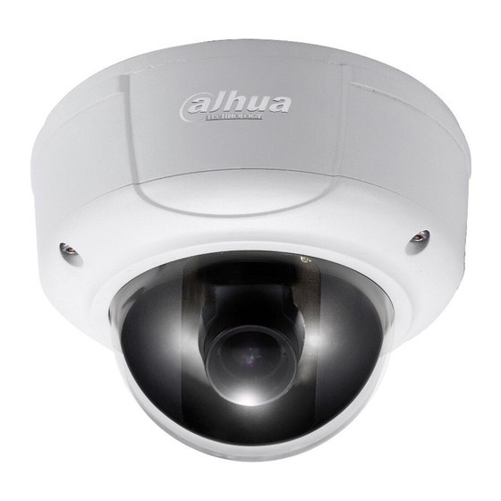
Summary of Contents for Dahua IPC-HDB3202P
- Page 1 HD (IR) Vandal Proof Network Dome Camera Quick Start Guide Version 1.1.0...
- Page 2 Welcome Thank you for purchasing our network camera! This quick start guide is designed to be a reference tool for your system. Please keep this start guide well for future reference. Please open the accessory bag to check the items one by one in accordance with the list below. Contact your local retailer ASAP if something is missing or damaged in the bag.
- Page 3 The grounding studs of the product are recommended to be grounded to further enhance the reliability of the camera. 6. Daily Maintenance Please shut down the device and then unplug the power cable before you begin daily maintenance work. Do not touch the CCD (CMOS) optic component. You can use the blower to clean the dust on the lens surface.
-
Page 4: Table Of Contents
Table of Contents Structure ............................1 Dimensions........................1 Port Description ......................1 Bidirectional talk ......................5 1.3.1 Device-end to PC-end ..................5 1.3.2 PC-end to the Device-end..................6 Alarm Setup........................6 Device Installation ........................8 Device Installation Introduction ..................8 Device Installation Steps.....................8 2.2.1 General Installation ....................8 2.2.2 Manual Zoom Lens Focus Operation...............12 2.2.3 Side Cable Exit ....................12 2.2.4 Cable Connection....................13 Micro SD Card Installation ..................14... -
Page 5: Structure
1 Structure 1.1 Dimensions You can refer to the following figures for dimension information. The Unit is mm. See Figure 1-1 and Figure 1-2. Figure 1-1 Figure 1-2 1.2 Port Description For the non-IR series product, the interface is shown as in Figure 1-3 and Figure 1-4. - Page 6 Figure 1-3 Figure 1-4 For the IR motorized zoom lens series product, the interface is shown as in Figure 1-5 and Figure 1-6.
- Page 7 Figure 1-5 Figure 1-6 For the IR manual zoom lens series product, the interface is shown as in Figure 1-7 and Figure 1-8.
- Page 8 Figure 1-7 Figure 1-8 Please refer to the following sheet for external connection port definition information. Port Port Name Connector Function Description power POWER Connect to AC 24V power. port DC 12V power POWER Connect to DC 24V power. port Cable exit Cable exit.
-
Page 9: Bidirectional Talk
connected cable RJ45 network Ethernet port Network cable port. port It includes alarm input/output, audio I/O port and analog output. Reset button. It is to restore factory RESET Reset button default setup. AUTO Adjust lens angle of view and 5-direction button FOCUS definition. -
Page 10: Pc-End To The Device-End
You can see the button becomes orange after you enabled the bidirectional talk function. Click Talk button again to stop the bidirectional talk function. Listening Operation At the device end, speak via the speaker or the pickup, and then you can get the audio from the earphone or sound box at the pc-end. - Page 11 Alarm input: When the input signal is idle or grounded, the device can collect the different statuses of the alarm input port. When the input signal is connected to the 5V or is idle, the device collects the logic “1”. When the input signal is grounded, the device collects the logic “0”. Figure 1-10 Please refer to the following figure for alarm output information.
-
Page 12: Device Installation
2 Device Installation Important Before you complete the installation and setup, do not remove the electrostatic attraction film on the transparent enclosure. Otherwise it may result in injury. After remove electrostatic attraction film, do not touch dome enclosure in case it may leave stain. - Page 13 Step 1 Take the installation position map from the accessories bag and then paste it on the installation ceiling or the wall according to the monitor area. Please dig three bottom holes of the plastic expansion bolts according to the map. Take three expansion bolts from the accessories bag and then insert them to the holes you just dug and then fix firmly.
- Page 14 Figure 2-4 Step 5 Please refer to the Step 3 to put the driver module back to the metal hooks of the chassis. Then use the inner hex wrench to secure the two inner hex screws to the chassis. Then connect the network cable and the power terminal.
- Page 15 Lock Screw A Adjust lend pan rotation angle. Figure 2-6 c). Lens tilt rotation angle. Please refer to Figure 2-7 to unfasten the lock screw B and lock screw C and adjust the tilt monitor angle to the proper position. Then fix the lock screw B and lock screw C. The tilt angle ranges from -23°~+73°.
-
Page 16: Manual Zoom Lens Focus Operation
Please note Figure 2-6 and Figure 2-7 is based on the IR motorized zoom camera. For the IR manual zoom camera and non-IR series product, the lock screw position and the lens angle adjustment are the same. Step 7 Line up the dome camera protection enclosure to the cable exit on the side panel. Put the enclosure back and then use the inner hex wrench to secure the 3 inner hex screws firmly. -
Page 17: Cable Connection
Figure 2-9 to form a cable exit. Put the plastic decoration plug back to the chassis and then pull the cable through the side panel of the chassis. Dig through here Figure 2-9 For some special user, he may need the metal protection tube to protect when he pulls through the cable from the side cable. -
Page 18: Micro Sd Card Installation
Step 2 Before you go to the Step 4 in the chapter 2.2.1 installation steps, please pull through cable with the waterproof airproof plug to the device chassis via the installation hole at the bottom of the chassis and then connect the cable pins. Step 3 Refer to Step 4 and Step 5 in the chapter 2.2.1 installation steps to install and connect the cable pin to the device and then follow the proper steps to go on the installation. -
Page 19: Quick Configuration Tool
3 Quick Configuration Tool 3.1 Overview Quick configuration tool can search current IP address, modify IP address. At the same time, you can use it to upgrade the device. Please note the tool only applies to the IP addresses in the same segment. 3.2 Operation Double click the “ConfigTools.exe”icon, you can see an interface is shown as in Figure 3-1. - Page 20 Figure 3-2 Select the “Open Device Web” item; you can go to the corresponding web login interface. See Figure 3-3. Figure 3-3 If you want to modify the device IP address without logging in the device web interface, you can go to the configuration tool main interface to set.
- Page 21 Figure 3-4 After you logged in, the configuration tool main interface is shown as below. See Figure 3-5. Figure 3-5 For detailed information and operation instruction of the quick configuration tool, please refer to the Quick Configuration Tool User’s Manual included in the resources CD.
-
Page 22: Web Operation
4 Web Operation This series network camera product supports the Web access and management via PC. Web includes several modules: Monitor channel preview, system configuration, alarm and etc. 4.1 Network Connection Please follow the steps listed below for network connection. Make sure the network camera has connected to the network properly. - Page 23 Figure 4-2 If it is your first time to login in, system pops up warning information to ask you whether install control webrec.cab or not after you logged in for one minute. Please click OK button, system can automatically install the control. When system is upgrading, it can overwrite the previous Web too. If you can’t download the ActiveX file, please check whether you have installed the plug-in to disable the control download.
- Page 24 Figure 4-4 Please refer to the Web Operation Manual included in the resource CD for detailed operation instruction.
-
Page 25: Faq
5 FAQ I can not boot up Please click RESET button for at least five seconds to restore the device or factory default setup. operate properly. The water leakage The unauthorized front or rear cap remove many result in water occurred. -
Page 26: Appendix Toxic Or Hazardous Materials Or Elements
Appendix Toxic or Hazardous Materials or Elements Toxic or Hazardous Materials or Elements Component Name Cr VI PBDE Circuit Board ○ ○ ○ ○ ○ ○ Component Device Case ○ ○ ○ ○ ○ ○ Wire and Cable ○ ○ ○...
Need help?
Do you have a question about the IPC-HDB3202P and is the answer not in the manual?
Questions and answers