
Related Manuals for Pro'sKit MT-2017


Summary of Contents for Pro'sKit MT-2017
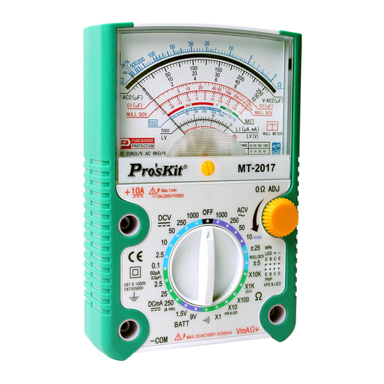
- Page 1 MT-2017 Protective Function Analog Multimeter User’s Manual Edition 2013 ©2013 Copyright by Prokit’s Industries Co., Ltd.
- Page 2 INTRODUCTION This Multi-meter is an accurate, safe, battery operated, rear tilt-stand, easy to operate handheld instrument with robust protective holster alongside and the adjustable back tilt device with hook-up design. It can offer accurate, reliable measurement of DC/AC Voltage, +/-DCV, DC Current, Resistance and Diode, LED, Transistor, Decibels, Continuity test and Capacitance with very high sensitive quality movement, double-sided glass-epoxy PCB &...
- Page 3 Test Range Accuracy Remarks Functions 3% FSD. DC V 0-0.1-2.5-10-50- Input Impendence: 4% FSD. 250 V-1000V 20KΩ/V Overload For 1000V Protection: Max. 1000V AC/DC BUT 0.1V/2.5V/10V 250V Max. Input Impedance: 40KΩ/V 5% FSD. Null DCV ±-5V, ±25V Overload 1000V Max.
- Page 4 3% FSD. Capacitan 0.025-0.25-25uF Use the optional ce (uF) (C2) Accessory Kit (MT-2007-C) 2000uF(C1) Approx. Use the R x 1K range Value 5% of BATT 0 ~ 1.5V: GOOD Load Current: Check - ? – BAD ARC of 270mA for 1.5V 0 ~ 9V: GOOD Scale...
- Page 5 scale. (-) Jack: Plug-in connector at the lower left on the panel for Black, negative test lead. (+) Jack: Plug-in connector at the lower right on the panel for Red, positive test lead. OPERATING INSTRUCTIONS CAUTION When making voltage or current measurements, develop the habit of turning off all power to the circuit under test.
- Page 6 PCB. If it’s blown, replace it. (See fuse replacement.) 6. Avoid placing the meter where extreme shock or continuous vibration is encountered and do not store in excessively hot or damp places. Although very rugged, the meter is a sensitive measuring device and should be handled carefully &...
- Page 7 OPERATION PROCEDURES DC Voltage Measurement WARNING: WITH EXTREME CARE WHEN MAKING MEASUREMENTS FOR HUGE VOLTAGE. DO NOT TOUCH TERMINAL OR PROBE ENDS. 1. Set the selector switch to the appropriate DCV range to be used. 2. Connect the BLACK test lead to the “-COM” jack and the RED test lead to the “+”...
- Page 8 AC Voltage Measurement WARNING: WITH EXTREME CARE WHEN MAKING MEASUREMENTS FOR HUGE VOLTAGE. DO NOT TOUCH TERMINAL OR PROBE ENDS. 1. Set the selector switch to the appropriate ACV range to be used and connect the test leads across the circuit or load under measurement.
- Page 9 The Maximum terminal voltage drop is 250mV except for the 10A range. Note: If connected incorrectly with the voltage at these ranges, quickly remove the test leads from the circuit as to avoid damage to this tester. (This tester can afford the voltage <250V DC/AC rms. for the period of 5 seconds max.) Resistance Measurement WARNING: DO NOT APPLY VOLTAGE TO MEASURING...
-
Page 10: Continuity Test
Diode Measurement 1. Set the selector switch to the appropriate Ω range to be used. NOTE: To test the diode while current below 0.060 mA at X 10K range; current below 0.15 mA at X 1K range; current below 1.5 mA at X 100 range;... - Page 11 Transistor hFE and LED Test 1. Set the selector switch to the R X 10 range. FOR Measuring Transistor hFE 2. Take note the type of transistor “PNP” or “NPN” and then insert the transistor terminals of the Emitter, Base and Collector separately into the proper holes of the socket on the front panel.
- Page 12 Decibels Measurement Set the selector switch to AC 10V range. Connect the BLACK test lead to the “-COM” jack and the RED test lead to the Red “+” jack. Connect the test leads to the measuring circuit specially in series with a 0.047μF/400V Metalized Polyester Capacitor. And then read the bottom Red dB scale.
- Page 13 1. For Measuring the Capacitor over 25uF: Set the selector switch to the R X 1K range. Connect the BLACK test lead to the “-COM” jack and the RED test lead to the Red “+” jack. Connect the test leads to the capacitor to be measured (Note the polarity of capacitor).
-
Page 14: Troubleshooting
Troubleshooting Nevertheless, problems or malfunctions may occur. For this reason, the following is a description of how you can eliminate possible malfunctions yourself: Error Possible cause The multimeter does Are the batteries exhausted? Is the not work. power indicator lit? Check the state of the batteries and the fuse 0.5A. - Page 15 MAINTENANCE Replacement for Battery and/or Fuse should only be done after the test leads have been disconnected and POWER OFF. 1. Battery Replacement 1). Note the condition of the batteries using the procedure described above, if the battery needs to be replaced, remove the screw and open the upper cover of the battery cabinet on the rear case.
- Page 16 MT-2017 26 檔指針型防誤測三用電錶 操作使用說明書 特點: 本機是指針式,防誤測全保護,斜立型三用電錶(附晶體 LED 座,短 路蜂鳴及 10A 檔)。具有以下基本特點和參數如下: - 斜立型,可調後蓋支撐架(拉出後,向上轉動 90 度, 壓下可固定) ; 附帶掛鈎設計(支撐架向上轉動 180 度伸出後蓋,以便懸掛) 。 - 配置玻璃釺維環氧樹脂鍍金盤雙面電路板,日系電池,並通過 CE 認證。 - 檔位切換簧片採用彈簧寶石軸承及二極體雙向限幅電路 - 具有全面的防誤測超載保護電路及速斷型保險絲多重保護 - 具有緊湊的兩側軟性防滑減振保護套 - 可測直流電壓和中間零位正負直流電壓,直流電流(最大 10A) , 交流電壓,電阻,電晶體,二極體,LED,電池,短路蜂鳴, 和電 容(2000uF Max.) 等.
- Page 17 規格表: 測試功能 檔位 準確度 說明 輸入阻抗:20KΩ/V 直流電壓 0-0.1-2.5-10-50-250-1 ±3%FSD(滿刻度) 超載:Max 1000V 000V ±4%FSD(1000V 檔) 但在 0.1V/2.5V/10V 各 檔,250V Max. 正負直流 輸入阻抗:40KΩ/V; 電壓 DC ±5V/±25V ±5% FSD.(滿刻度) 超載:Max.250V Null DCV 輸入阻抗:9KΩ/V ±4%FSD(滿刻度) 交流電壓 超載:Max.1000V 0-10-50-250V-1000V ±5%FSD(1000V 檔) 但 10V/50V 檔,250V 頻率範圍:40~10KHz Max.
- Page 18 超載:最高 AC/DV250V, 最低 DC/AC 50V, 超載最大測試時間 5 秒。 三極管檢 hFE: 0-1000 參考值 使用 Ω×10 檔 測 LED, Diode 參考值 使用 Ω×10 檔 Check 超載:最高 AC/DC Continuity 200 歐姆左右以內, 250V,最低 DC/AC Check 蜂鳴器會響。 50V 超載最大測試時 間 5 秒。 1.5V5 號電池:2 節, 內部電源...
- Page 19 Null DC Volt(V) DC 50μA ×1 直流電流 2.5mA ×0.01 (安培) 25mA ×0.1 DC Current (A) 250mA ×1 ×1 AC 10V ×1 交流電壓 ×1 (伏特) 250V ×1 AC Volt(V) 1000V ×100 Ω×10 IC/IB ×1 Ω×10K μA×1 ×1K μA×10 ×100 μA×100 二極體 Diode ×10 mA×1 ×1...
- Page 20 用於測量電池、放大器電路、通訊設備電源、電子管和電晶體 電路偏 壓的直流電壓。6 個檔位元中的每一個檔位元標記,分 別表示該檔的最大電壓示值。 (※不確定之直流電壓,應從最大值依序向下調整量測) 2. 中值零位正負直流電壓: (不可測量任何交流電壓!) 本功能專用檢測電子電路的正負電平。通過表棒接入電路,可 直接查看刻度讀數。 注意:在此檔位時,可用歐姆電調零將指針設置在中間位置。 若無法調到中值零位,則有可能是 9V 電池電量不足。請 檢查電池。 3. 交流電壓: 用於測量商業交流電壓、交流電源電路、交流放大信號級等。4 個檔位元中的每一個檔位元標記,分別表示該檔的最大電壓示 值.(※不確定之交流電壓,應從最大值依序向下調整量測) 4. 直流電流: (不可測量任何交流電流或電壓!) 用於測量直流電源控制裝置的電流消耗、電晶體電路的工作電流 等。5 個檔位元中的每一個檔位元標記,分別表示該檔的最大電 流示值。 (※不確定之直流電流,應從最大值依序向下調整量測) 注意:本機具有防誤測保護電路。可短時(5 秒內)承受低於 AC/DC 250V 的電壓衝擊,僅爆保險絲。 5. 電阻:(※此功能不能測試帶電壓電路) 測量電阻值和測試線路和線路間的連通性。5 個檔中的每一個 檔位元標記,分別表示該檔乘數。(K 即 X1000) 注意:本機在電阻檔具有防誤測保護電路。可短時(5 秒內)...
- Page 21 將量程選擇旋鈕置於 Buzz 檔,當被測電路<200ohm, 蜂鳴器鳴 叫。 注意:本機在檔位元具有防誤測保護電路。可短時(5 秒內) 承受低於 AC/DC 250V 的電壓衝擊,僅爆保險絲。 7. 電池測試: (※電池能用於小的晶體管收音機,但不能用作裝的 電源。) 好電池:指針停留在綠色(GOOD)範圍內。電量不足:指針停在 “?”尚可使用範圍內。 壞電池:指標停在紅色(BAD)區域。 注意:本機在檔位元具有防誤測保護電路。可短時(5 秒內) 承受低於 AC/DC 250V 的電壓衝擊,僅爆保險絲。 8. dB 測試: 本機測量 dB 值時,要接入表棒並串接一個 0.047μF/400V 電解 電容,然後檢視電錶讀數。 測量在 10V 檔上進行,可直接讀取 dB 刻度(-10dB~+22dB)。 測量在 50V 檔上進行時,刻度讀值要加 14dB,才是實際 dB 值。 測量在...
- Page 22 10. 二極體測試: (1) 將量程選擇旋鈕置於“Ω”檔上有選擇的量程位置,X10K 用 於 0~60μ A 測試 , X1K 用於 0~150μ A , X100 用於 0~1.5m A,X10 於 0~15mA,X1 用於 0~150mA 測試。 (2) 將電錶與二極體連接測 IF(正向電流),將電錶的“COM”端 與二極體陽極相連,“+”端與二極體陰極相連,對於 IR(反 向電流)測試連接方法和 IF 相反。 (3) 在 LI 刻度線讀出 IF 或 IR (4) 在測試 IF 或 IR 同時在 LV 刻度上,讀出二極體正向(反向) 電壓。...
- Page 23 電容量程 換算倍數 0.025uF X 0.0001 0.25uF X 0.001 25uF X 0.1 g. 測試完後,須將電源開關關掉。 日常保養 維修更換電錶內部電池和保險絲管時,必須將表棒從電錶上移調, 並切斷電源。 1). 電池更換: 打開電錶的上部電池倉後蓋,從電池座中拿出不好的電池。再 將新的同規格電池放入原位,並注意電池的正負極性,然後, 蓋上後蓋並擰緊螺釘。 2). 保險絲管更換: 首先移去電錶兩側的軟性保護套,然後打開電錶的後蓋,從保 險絲座中拿出不好的保險絲管。 再將新保險絲管(0.5A/250V或 10A/250V,Φ5*20mm)換上。必 須用同規格UL認證的保險絲管。 然後,蓋上後蓋並套上保護套, 最後擰緊後蓋螺釘。 (本電錶的電池倉後蓋下一般設有備用保險絲管) 。...
- Page 24 ©2013 Prokit’s Industries Co., Ltd. All rights reserved. 2013001(T)
Need help?
Do you have a question about the MT-2017 and is the answer not in the manual?
Questions and answers