
Related Manuals for Pro'sKit MT-1270


Summary of Contents for Pro'sKit MT-1270
- Page 1 MT-1270 3 1/2 Digital Multimeter User’s Manual Edition 2013 ©2013 Copyright by Prokit’s Industries Co., Ltd.
- Page 2 General This instrument is a high performance and accuracy digital multimeter driven by 9V battery. It uses the LCD with 26mm high figure to make the reading clear and the operation more convenient. This instrument can measure DC and AC Voltage, DC and AC Current, Resistance, Capacitance, Frequency, Diode, Transistor, Continuity, Temperature, etc.
- Page 3 Property 1. General Properly 1-1. Display: LCD 1-2. Max display: 1999 (3 1/2 digit) automatic polarity display. 1-3. Measuring method: dual-integral A/D converter 1-4. Sampling Rage: approx. 3 times / sec. 1-5. Overrange display: LCD displays “1” or “-1” 1-6. Low battery display: “ ”symbol appearance 1-7.
- Page 4 2-3-2.(ACV) Range Accuracy Resolution ±(0.8%+5d) 10mV 200V 100mV 750V ±(1.2%+10d) Input Impedance: 10 MΩ at all the ranges. Overload protection: 1000V DC or AC peak value. Frequency Response: (40~200)Hz at the Range below 20V (40~100)Hz at the Range 200V~750V Display: average value response (RMS of sine wave) 2-3-3.(DCA)...
- Page 5 fast-blown fuse Frequency response: (40~200)Hz Display: average value response (RMS of sine wave) 2-3-5.(Ω) Range Accuracy Resolution 200Ω ±(0.8%+5d) 0.1Ω 2kΩ 1Ω 20kΩ 10Ω ±(0.8%+3d) 200kΩ 100Ω 2MΩ 1kΩ 20MΩ ±(1.0%+25d) 10kΩ 200MΩ ±(5.0%+30d) 100kΩ Open circuit voltage: less than 0.7V Overload protection: 250V DC and AC peak value.
- Page 6 2-3-7.(f) Range Accuracy Resolution 20kHz ±(3.0%+18d) 10Hz Input sensitivity: 1V RMS value Overload protection: 250V DC or AC peak value (less than 15 seconds) 2-3-8.(℃) Accuracy Accuracy Resolution Range (-20~400)℃ ±(1.0%+5d) 1℃ (400~1000)℃ ±(1.5%+15d) 1℃ Sensor: K Type Thermocouple, banana plug WARNING: DO NOT input any voltage at this range for safety! 2-3-9.Diode and Continuity Test...
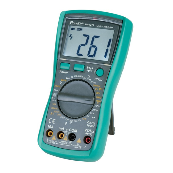
- Page 7 Operation Method 1. Front Panel Description LCD: Display the measuring value HOLD Key: Press the key, the present measuring value is held on LCD, and appear “Hold” symbol, press the key again, disappear “Hold” symbol, and exist the Date Hold function Range Knob: Switch the measuring function and range...
- Page 8 2. If LCD displays “1”, it indicates overload, should turn the knob to the higher range. 3. ACV Measurement 1. Insert the black lead into “COM” terminal, and the red lead into “V/Ω/Hz” terminal, turn the knob to the ACV range, then connect the test leads across the tested circuit.
- Page 9 5. ACA Measurement 1. Insert the black lead into “COM” terminal, and red lead into “mA” terminal (max 200 mA), or red lead into “10A” terminal (max 10A) 2. Tern the knob to the ACA Range, then connect the test leads into the tested circuit in series.
-
Page 10: Frequency Measurement
7. Capacitance Measurement 1. Insert the red lead into “mA” terminal, and black lead into “COM” terminal 2. Turn the knob to the Capacitance Range, then connect the test leads across the tested capacitance (note the polarity of the red lead is positive) Note:... - Page 11 measuring the high voltage circuit. 6. Do not input more than 250V DC or AC peak value to avoid damaging the instrument. 9. .Diode and Continuity Test 1. Insert the black lead into “COM” terminal, and red lead into “V/Ω/Hz” terminal (Note: the polarity of red lead is positive) 2.
- Page 12 Maintenance This is a high precise instrument; do not try to modify the inner circuit at will. Keep the instrument dry, and keep it away from dust and shock Do not store and use the instrument in high humility, high temperature, combustible, explosive and strong magnetic places.
-
Page 13: Fault Elimination
FAULT ELIMINATION If the instrument does not work properly, the below methods can help you to solve the problems quickly. If the fault still can’t be eliminated, please contact the maintenance center or the distributors: Fault Solution Power off –pls turn on the power ... - Page 14 MT-1270 3 1/2 數位電錶 使用說明書 一、概述 該系列儀錶是一種性能穩定、用電池驅動的高可靠性數位萬用表。 儀錶採用 26mm 字高 LCD 顯示器,讀數清晰、更加方便使用。 此系列儀錶可用來測量直流電壓和交流電壓、直流電流和交流電 流、電阻、電容、頻率、二極體、三極管、通斷測試、溫度等參數。 整機以雙積分 A/D 轉換為核心,是一台性能優越的工具儀錶,是實 驗室、工廠、無線電愛好者及家庭理想工具。 二、安全事項 該系列儀錶在設計上符合 IEC1010 條款(國際電工委員會頒佈 的安全標準) ,在使用之前,請先閱讀安全注意事項。 各量程測量時,禁止輸入超過量程的極限值;36V 以下的電壓 為安全電壓,在測高於 36V 直流、25V 交流電壓時,要檢查錶 棒是否可靠接觸,是否正確連接、是否絕緣良好,以避免電擊。 換功能和量程時,錶棒應離開測試點。 選擇正確的功能和量程,謹防誤操作,該系列儀錶雖然有全量 程保護功能,但為了安全起見,仍請您多加注意。 在電池沒有裝好和後蓋沒有上緊時,請不要使用此表進行測試 工作。 測量電阻時,請勿輸入電壓值。 在更換電池或保險絲前,請將測試錶棒從測試點移開,並關閉 電源開關; 安全符號說明:...
- Page 15 三、特性 1.一般特性 1-1.顯示方式:LCD 液晶顯示; 1-2.最大顯示:1999(3 1/2 位元)自動極性顯示; 1-3.測量方式:雙積分式 A/D 轉換; 1-4.採樣速率:約每秒鐘 3 次; 1-5.超量程顯示:最高位顯“1"或“-1"; 1-6.低電壓顯示:“ "符號出現; 1-7.工作環境: (0~40)℃,相對濕度<80% ; 1-8.電源:9V 電池(NEDA1604/6F22 或同等型號) ; 1-9.體積(尺寸) :182 x 90 x 46 (長×寬×高) ; 1-10.重量:約 320 g(不含 9V 電池) ; 1-11.附件:使用說明書一本,CATIII 錶棒一付、溫度探棒一付。 電晶體/電容測試座 2.技術特性...
- Page 16 2-3-2.交流電壓(ACV) 準確度 準確度 分辨力 量程 ±(0.8%+5d) 10mV 200V 100mV 750V ±(1.2%+10d) 輸入阻抗:所有量程為 10MΩ; 超載保護:1000V 直流或交流峰值; 頻率回應:20V 以下量程: (40~200)Hz, 200V~750V 量程: (40~100)Hz; 顯 示:正弦波有效值(平均值回應) 。 2-3-3.直流電流(DCA) 準確度 準確度 分辨力 量程 ±(0.8%+10d) 20mA 10uA 200mA 100uA ±(1.2%+8d) 10mA ±(2.0%+5d) 最大輸入壓降:200mV; 最大輸入電流:10A(測試時間不超過 10 秒) ; 超載保護:0.2A/250V 自恢復保險絲,10A/250V 速熔保險絲。...
- Page 17 超載保護:0.2A/250V 自恢復保險絲,10A/250V 速熔保險絲; 頻率回應:(40~200)Hz; 顯 示:正弦波有效值(平均值回應) 。 2-3-5.電阻(Ω) 準確度 準確度 分辨力 量程 200Ω ±(0.8%+5d) 0.1Ω 2kΩ 1Ω 20kΩ 10Ω ±(0.8%+3d) 200kΩ 100Ω 2MΩ 1kΩ 20MΩ ±(1.0%+25d) 10kΩ 200MΩ ±(5.0%+30d) 100kΩ 開路電壓:小於 0.7V; 超載保護:250V 直流和交流峰值; 注意事項:在使用 200Ω 量程時,應先將錶棒短路,測得引線電 阻,然後在實測中減去; 警 告:為了安全在電阻量程禁止輸入電壓值! 2-3-6.電容(C) 準確度...
- Page 18 2-3-7.頻率(freq) 量 程 准 確 度 分辨力 20kHz ±(3.0%+18d) 10Hz 輸入靈敏度:1V 有效值; 超載保護:250V 直流或交流峰值(不超過 15 秒)。 2-3-8.溫度(℃) 準確度 準確度 分辨力 量程 (-20~400)℃ ±(1.0%+5d) 1℃ (400~1000)℃ ±(1.5%+15d) 1℃ 感測器:K 型熱電偶(鎳鉻—鎳矽)香蕉插頭。 警 告:為了安全在此量程禁止輸入電壓值! 2-3-9.二極體及通斷測試 量程 顯示值 測試條件 正 向 直 流 電 流 約 二極體正向壓降...
- Page 19 四、使用方法 (一).操作面牌說明 1. 液晶顯示器:顯示儀錶測量的數值 2. HOLD 保持開關:按下此功能, 儀錶當前所測數值保持在螢幕上 並出現“Hold"符號,再次按下 開關彈起,“Hold"符號消失, 退 出保持功能狀態 3. 旋鈕開關:用於改變測量功能及 量程 4. 小 於 200mA 電 流 測 試 , 溫 度 “+", 電容,電晶體測試插座 5. 10A 電流測試插座 6. 電壓、電阻、頻率、通斷、二極 體測試插座 7. 公共地, 溫度“-",頻率, 電容, 電晶體, 二極體, 通斷測試插座 8.
- Page 20 注意: 1. 如果事先對被測電壓範圍沒有概念,應將量程開關轉到最高 的檔位元,然後根據顯示值轉至相應檔位上。 2. 如螢幕顯“1",表明已超過量程範圍,須將量程開關轉至較 高檔位元上。 (四).直流電流測量 1. 將黑錶棒插入“COM"插座,紅錶棒插入“mA"插座中 (最 大為 200mA) ,或紅錶棒插入“10A"插座中(最大為 10A) ; 2. 將量程開關轉至相應 DCA 檔位上, 然後將儀錶的錶棒串聯接 入被測電路中,被測電流值及紅色錶棒點的電流極性將同時 顯示在螢幕上。 注意: 1. 如果事先對被測電流範圍沒有概念,應將量程開關轉至較高 檔位元,然後按顯示值轉至相應檔上; 2. 如螢幕顯“1",表明已超過量程範圍,須將量程開關轉至較 高檔位元上; 3. 最大輸入電流為 200mA 或者 10A (視紅錶棒插入位置而定) , 在測量 10A 時要注意,連續測量大電流將會使電路發熱,影 響測量精度甚至損壞儀錶。...
- Page 21 (六).電阻測量 1. 將黑錶棒插入“COM"插座,紅錶棒插入“V/Ω/Hz"插座; 2. 將量程開關轉至相應的電阻量程上,然後將兩錶棒跨接在被 測電阻上。 注意: 1. 如果電阻值超過所選的量程值,則會顯“1",這時應將開關 轉至較高檔位元上;當測量電阻值超過 1MΩ 以上時,讀數 需幾秒時間才能穩定,這在測量高電阻時是正常的; 2. 當輸入端開路時,則顯示超載情形; 3. 測量線上電阻時,要確認被測電路所有電源已關斷及所有電 容都已完全放電才可進行。 (七).電容測量 1. 將紅錶棒插入“mA"插座,黑錶棒插入“COM"插座; 2. 將量程開關轉至相應之電容量程上,錶棒對應極性(注意紅 錶棒極性為“+"極)接入被測電容。 注意: 1. 如果事先對被測電容範圍沒有概念,應將量程開關轉到最高 的檔位;然後根據顯示值轉至相應檔位上; 2. 如螢幕顯“1",表明已超過量程範圍,須將量程開關轉至較 高的檔位上; 3. 在測試電容前,螢幕顯示值可能尚未回到零,殘留讀數會逐 漸減小,但可以不予理會,它不會影響測量的準確度; 4. 大電容檔測量嚴重漏電或擊穿電容時,將顯示一些數值且不 穩定; 5. 請在測試電容容量之前,必須對電容應充分地放電,以防止 損壞儀錶。 6.
- Page 22 (八).頻率測量 1. 將錶棒或遮罩電纜接入“COM"和“V/Ω/Hz"輸入端; 2. 將量程開關轉到頻率檔上,將錶棒或電纜接在信號源或被測 負載上。 注意: 1. 輸入超過 10Vrms 時,可以讀數,但可能超差; 2. 在雜訊環境下,測量小信號時最好使用遮罩電纜; 3. 在測量高電壓電路時,千萬不要觸及高壓電路; 4. 禁止輸入超過 250V 直流或交流峰值的電壓值,以免損壞儀 錶。 (九).二極體及通斷測試 1. 將黑錶棒插入“COM"插座,紅錶棒插入“V/Ω/Hz"插座 (注意紅錶棒極性為“+"極) ; 2. 將量程開關轉至“ "檔,並將錶棒連接到待測試二極 體,讀數為二極體正向壓降的近似值; 3. 將錶棒連接到待測線路的兩點,如果內置蜂鳴器發聲,則兩 點之間電阻值低於約(70±20)Ω。 (十).溫度測量 測量溫度時,將熱電偶感測器的冷端(自由端)負極插入 “COM"插座 , 正極插入“mA"插座中 , 熱電偶的工作端 (測 溫端)...
- Page 23 五、儀錶保養 該系列儀錶是一台精密儀器,使用者不要隨意更改電路。 請注意防水、防塵、防摔; 不宜在高溫高濕、易燃易爆和強磁場的環境下存放、使用儀 錶; 請使用濕布和溫和的清潔劑清潔儀錶外表,不要使用研磨劑 及酒精等烈性溶劑; 如果長時間不使用,應取出電池,防止電池漏液腐蝕儀錶; 4-1.注意 9V 電池使用情況,當 LCD 顯示出“ "符號時, 應更換電池,步驟如下: 4-1-1.打開電池盒; 4-1-2.取下 9V 電池,換上一個新的電池,雖然任何標準 9V 電池都可使用 , 但為加長使用時間建議使用鹼性電池 4-1-3.裝回電池盒。 六、故障排除 如果您的儀錶不能正常工作,下面的方法可以幫助您快速解決一 般問題。如果故障仍排除不了,請與維修中心或經銷商聯繫。 故障現象 檢 查 部 位 及 方 法 電源未接通; 保持開關; 沒顯示 ...
Need help?
Do you have a question about the MT-1270 and is the answer not in the manual?
Questions and answers