
Related Manuals for Pro'sKit MT-3109


Summary of Contents for Pro'sKit MT-3109
- Page 1 MT-3109 AC/DC Digital Clamp Multimeter User’s Manual Edition 2011 ©2011 Copy Right by Prokit’s Industries Co., Ltd.
- Page 2 MT-3109 AC/DC Digital Clamp Multimeter Overview This Operating Manual covers information on safety and cautions. Please read the relevant information carefully and observe all the Warnings and Notes strictly. Warning To avoid electric shock or personal injury, read the “Safety Information"...
- Page 3 MT-3109 AC/DC Digital Clamp Multimeter Use the Meter only as specified in this operating manual, otherwise the protection provided by the Meter may be impaired. In this manual, a Warning identifies conditions and actions that pose hazards to the user, or may damage the Meter or the equipment under test.
- Page 4 MT-3109 AC/DC Digital Clamp Multimeter Do not carry out the measurement when the Meter's back case and battery compartment are not closed to avoid electric shock. Do not input higher than 600V between the two Meter's input terminal to avoid electric shock and damages to the Meter.
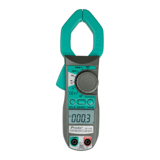
- Page 5 MT-3109 AC/DC Digital Clamp Multimeter International Electrical Symbols AC (Alternating Current) DC (Direct Current) AC or DC Grounding Double Insulated Warning. Refer to the Operating Manual Deficiency of Built-In Battery Continuity Test Diode Capacitance Test Fuse Conforms to Standards of European Union The Meter Structure (see figure 1) 1.
- Page 6 MT-3109 AC/DC Digital Clamp Multimeter Rotary Switch Below table indicated for information of rotary switch positions. Rotary Switch Function Position Power is turned off AC or DC voltage measurement Ω Resistance measurement : Diode test : Continuity test Hz / Duty %...
- Page 7 MT-3109 AC/DC Digital Clamp Multimeter Button Operation Performed Press SELECT button to select the alternate Select functions marked in blue color on the Meter's faceplate including Hz, Duty%, , and 400 After the Meter entering Sleep Mode, press and hold SELECT to turn the Meter on, it will disable the Sleep Mode feature.
- Page 8 MT-3109 AC/DC Digital Clamp Multimeter Meaning Symbol Indicator for AC voltage or current Indicator for DC voltage The battery is low. Warning: To avoid false readings, which could lead to possible electric shock or personal injury, replace the battery as soon as the battery indicator appears.
- Page 9 MT-3109 AC/DC Digital Clamp Multimeter Measurement Operation A. DC/AC Voltage Measurement (see figure 3) Warning To avoid harms to you or damages to the Meter from electric shock, do not attempt to measure voltages higher than 600V AC/DC, although readings may be obtained The DC Voltage ranges are: 400mV, 4V, 40V, 400V and 600V.
- Page 10 -3109 AC /DC Digital Clamp Multimeter Warning To avoid damages to the Meter or to the devices under test, disconnect circuit power and discharge all the high-voltage capacitors before measuring resistance. The resistance ranges are: 400Ω, 4kΩ, 40kΩ,400kΩ,4 MΩ and 40MΩ. To measure resistance, connect the Meter as follows: 1.
- Page 11 MT-3109 AC/DC Digital Clamp Multimeter voltage drop across the junction. A good silicon junction drops between 0.5V and 0.8V. To test the diode out of a circuit, connect the Meter as follows: 1. Insert the red test lead into the Hz Duty% -i))-H VQ terminal and the black test lead into the COM terminal.
- Page 12 MT-3109 AC/DC Digital Clamp Multimeter 3. The buzzer may or may not sounds if the resistance of a circuit under test is between 50Ω to 100Ω 4. The buzzer does not sound if the resistance of a circuit under test is higher than 100Ω...
- Page 13 MT-3109 AC/DC Digital Clamp Multimeter F. Duty Cycle Measurement (see figure F. Duty Cycle Measurement (see figure Warning To avoid harms to you or damages to the Meter from electric shock, do not attempt to measure voltages higher than 600V AC/DC, although reading may be obtained.
- Page 14 MT-3109 AC/DC Digital Clamp Multimeter 3. Press the lever to open the transformer jaw. 4. Center the conductor within the transformer jaw, then release the Meter slowly until the transformer jaw is completely closed, Make sure the conductor to be tested is placed at the center of the transformer jaw, otherwise it will cause deviation.
- Page 15 MT-3109 AC/DC Digital Clamp Multimeter H. Capacitance measurement (see figure 10) figure 10 Warming To avoid damage to the Meter or to the equipment under test, disconnect circuit power and discharge all high-voltage capacitors before measuring capacitance. Use the DC voltage function to confirm that the capacitor is discharged.
-
Page 16: Specifications
MT-3109 AC/DC Digital Clamp Multimeter Specifications A. General Specifications: Maximum Voltage between any Terminals and grounding: Refer to different range input protection voltage. Display: 3 3/4 digits LCD display, Maximum display 3999 Polarity: Automatically display. Overloading: Display OL or -OL ... - Page 17 MT-3109 AC/DC Digital Clamp Multimeter Accurate Specifications Accuracy: +(a% reading + b digits). Operating temperature: 23℃±5℃ Relative humidity: ( 85%R.H) Temperature coefficient: 0.1x (specified accuracy)1℃ A. DC Voltage Overload Range Resolution Accuracy protection 400.0mV 0.1mV +(1 %+3) 4.000V +(1 %+1) 40.00V...
- Page 18 MT-3109 AC/DC Digital Clamp Multimeter C. Resistance Overload Range Resolution Accuracy protection 400.0Ω 100mΩ +(1.2%+5) 4.000kΩ 1Ω +(1 %+5) 40.00kΩ 10Ω 600Vp 400.0kΩ 10Ω 4.000MΩ 1kΩ +(1.2%+5) 40.00MΩ 10kΩ +(1.5%+5) D. Diode Test Range Resolution Accuracy Overload protection Display forward...
- Page 19 MT-3109 AC/DC Digital Clamp Multimeter F. Frequency Overload Range Resolution Accuracy protection 10Hz 0.00Hz 100Hz 0.01Hz 1kHz 0.1Hz 600Vp +(0.1 %+5) 10kHz 100kHz 10Hz 1MHz 100Hz 10MHz 1kHz reference only Remark: Input Sensitivity as follows: When ≤ 100kHz: ≥ 300mV rms;...
- Page 20 MT-3109 AC/DC Digital Clamp Multimeter Hold the Meter tight and press the lever to open the transformer jaw. Center the conductor within the transformer jaws, then release the Meter slowly until the transformer jaw is completely closed. Make sure the conductor to be tested is placed at the center of the transformer jaw, otherwise it will cause +1 .0% deviation based on the stated accuracy.
-
Page 21: Maintenance
MT-3109 AC/DC Digital Clamp Multimeter ●Change to AC: Change to AC by using average response method. Input sine wave, then adjust the reading until it is same as the effective value. J. Capacitance Range Resolution Accuracy Overload Protection Measure at REL... - Page 22 -3109 AC /DC Digital Clamp Multimeter B. Replacing the Battery (see figure 11) Warning To avoid false readings, which could lead to possible electric shock or personal injury, replace the battery as soon as the battery indicator " " appears. Make sure the transformer jaw and the test leads are disconnected from the circuit being tested before opening the case bottom.
- Page 23 MT-3109 AC/DC Digital Clamp Multimeter MT-3109 數位交直流鉗表 中文說明書 一、概述 MT-3109 是一種性能穩定、安全、可靠的 3 3/4 位交直流數字鉗形 表(以下簡稱鉗表)系列。整機電路設計以大規模積體電路雙積 分 A/D 轉換器為核心,全量程的過載保護電路,獨特的外觀設計 使之成為性能優越的專用電工儀表。鉗表可用於測量交直流電 壓、交直流電流、電阻、二極體、電路通斷及頻率等。本使用說 明書包括有關的安全訊息和警告提示等,請仔細閱讀有關內容並 嚴格遵守所有的警告和注意事項。 △警告! 在使用鉗表之前,請仔細閱讀有關“安全操作準則" 二、開箱檢查 打開包裝盒,取出儀表,請仔細檢查下列項目是否缺少或損壞︰ 項次 名稱 數量 使用說明書 1 本 表棒 1 組 帶夾短測試線 1 組 布包 1 個...
- Page 24 MT-3109 AC/DC Digital Clamp Multimeter 三、安全操作準則 請注意“警告標識△及警告字句"。警告表示對使用者構成危 險、對儀表或被測設備可能造成損壞的情況或行動。 本儀表嚴格遵循 GB4793 電子測量儀器安全要求以及 IEC61010-1 和 IECI010-2-032 安全標準進行設計和生產,符合雙重絕緣、過電 壓 CAT II 600V、CAT III 300V 和污染等 級 2 的安全標準。如果未能按照有關的操作說明使用鉗表,則可 能會削弱或失去鉗表為您提供的保護能力。 1. 使用前應檢查鉗表和表筆,謹防任何損壞或不止常的現象。如 發現本鉗表表筆、殼體絕緣已明顯損壞以及液晶顯示器等或者 您認為本鉗表己無法正常工作,請勿再使用本鉗表。 2. 後蓋及電池蓋沒有蓋好前嚴禁使用鉗表,否則有電擊危險。 3. 在進行測量時切記手指不要超過表筆擋手部位,不要接觸裸露 的電線、連接器及沒有使用的輸入端或正在測量的電路防止觸 電。 4. 測量前功能開關必須置於正確位置,嚴禁在測量進行中轉換檔 位,以防損壞鉗表。 5. 不要在鉗表終端及接地之間施加 600V 以上電壓,以防電擊和...
- Page 25 MT-3109 AC/DC Digital Clamp Multimeter 四、電氣符號︰ 雙重絕緣 AC(交流) 二極體 接地 DC(直流) 表內電池不足 警告提示 蜂鳴通斷 AC 或 DC(交流或直流) 高壓符號 中國技術監督局 製造計量器具許可證 符合歐洲共同體(European Uion)標準 電容測試 五、外表結構(見圖 1) 圖 1 1. 輸入端。 2. 液晶數字顯示。 3. 功能按鍵,選擇基本功能。 4. 測量功能轉盤。 5. 鉗頭板機:按壓板機, 使鉗頭張開, 若鬆開板機,則鉗頭局部再度密合。 6. 手部防護:為保護使用者手部碰碰觸到...
- Page 26 MT-3109 AC/DC Digital Clamp Multimeter 六、顯示符號(見圖 2) 1. 交流信號測量指示 2. 直流信號測量指示 3. 電池電量不足指示 4. 自動量程指示 5. 二極體測試指示 6. 連續檢測指示 7. 占空比測量指示 8. 數據保持指示 9. 相對值測量指示 10. 電阻測量單位(Ω 歐姆、kQ 千歐、 MQ 兆歐) 圖 2 11. 頻率測量單位 12. 電流測量單位(A 安培) 13. 電壓測量單位(mV 毫伏、V 伏特) 14....
- Page 27 MT-3109 C/DC Digital Clamp Multimeter 4. 自動關機︰在測量過程中,功能按鍵和轉盤開關在 1 5 分鐘內均 無動作時,鉗表會“自動關機"(休眠狀態) ,以節約電能; 要 取消自動關機功能,只要按著 SELECT 鍵開機,則自動關機功 能被取消。自動關機狀態下,按功能鍵(有效的按鍵操作,詳 見 6.)或是轉動轉盤開關,鉗表會“自動開機"(工作狀態) 。 注意︰在休眠狀態下按 SELECT 鍵喚醒,自動關機功能被取消。 5. 蜂鳴器︰在任一測量檔位按動任意功能按鍵,如果該鍵有效, 蜂鳴器會發“嗶"的一聲,無效則不發聲; 自動關機前約 1 分鐘 蜂嗚器會連續發出 5 聲警示; 關機前蜂嗚器會以 1 長聲警示。 6. 按鍵的有效性︰並非所有的按鍵操作在任一檔位上都是有效 的,只有有效的按鍵操作,才能選擇相應的操作功能或喚醒休 眠狀態下的儀表,見下表︰ 檔位...
- Page 28 MT-3109 AC/DC Digital Clamp Mu ltime 2.交流電壓測量(V )(見圖 4) △警告 圖 4 鉗表不得用於電壓大於 600V 交流/直 流導電的物體上 ﹡設置轉盤 將功能轉盤置於“ "測量檔。 ﹡選擇功能 按 SELECT 鍵選擇為交流電壓測量,最 初設置 為自動量程,按 REL△鍵可設置為手動 量程。 ﹡連接負載 在完成所有的測量操作後,要斷開表棒與被測電路的連接, 並從輸入端拿掉表棒。 圖 5 3.電阻測量(Ω) (見圖 5) △警告 在連接負載以前務必將電路電源切斷, 並將所有電容器放盡殘餘電荷 ﹡設定轉盤 將功能轉盤置於“Ω"測量檔。...
- Page 29 MT-3109 AC/DC Digital Clamp Multimeter 較好的結果。 在完成所有的測量操作後,要斷開表棒與被測電路的連接,並從 輸入端拿掉表棒。 △警告:在連接負載以前務必將電路電源切斷 ﹡設置轉盤到 位置 ﹡選擇功能 按 SLLECT 鍵選擇二極體測 ﹡連接負載 若將元件從電路中分離出來測量可得到較好的結果。 5.導通檢測( )(見圖 7) 圖 7 △警告 在連接負載以前務必將電路電源切斷,並 將所有電容器放盡殘餘電荷 ﹡設定轉盤 將功能轉盤置於“ "測量檔。 ﹡選擇功能 按 SELECT 鍵選擇. 導通檢測 ﹡連接負載 在導通測試中測量電阻小於 50Ω時蜂嗚 器會響,在 50Ω到 100Ω時蜂鳴器可能響 或不響,大於 100Ω 時蜂鳴器不響。...
- Page 30 MT-3109 AC/DC Digital Clamp Multimeter 7.占空比測量( Duty%)(見圖 9) △警告 圖 9 鉗表不得用於電壓大於 600V 交流/直流 導電的物體上 ﹡設定轉盤 將功能轉盤置於`Hz"測量檔。 ﹡選擇功能 按 REI△鍵可設定為 Duty%占空比測 最。 ﹡連接負載 在完成所有的測最操作後,要斷開表 筆與被測電路的連接,並從輸入端拿掉表筆。 圖 10 8.直流电流测量( ) (見圖 10) ﹡設定轉盤 將功能轉盤置於“40A "或 “400A "測量檔。 ﹡選擇功能 直流電流測量為最初設定值。 ﹡連接負載 按住板機不要突然鬆開,鉗頭內置的霍爾...
- Page 31 MT-3109 AC/DC Digital Clamp Multimeter 對熱、機械應力均有不同程度的敏感,撞擊會短時間引起讀數變 化。按住板機打開鉗頭,將鉗頭夾取待測導體,然後緩慢地放開 板機,直到鉗頭完全閉合,請確定待測導體是否被夾取在鉗頭的 中央,未置於鉗頭中心位置會產生附加誤差,鉗表一次只能測量 一個電流導體,若同時測量兩個或以上的電流導體,測量讀數會 是錯誤的。 1 0.電容測試( )(見圖 1 2) 圖 12 將功能轉盤置於" "測量檔 將紅色表棒插入“HzV Ω"插孔 , 黑表 棒插入“COM"插孔,並將表筆並聯到 被測電容上.從顯示器上讀取測量結果 九、技術指標 1.一般規格 液晶顯示︰3 3/4 位液晶顯示,最大顯示至 3999. 極性顯示︰自動正負極性顯示 過載顯示︰以“OL"或“-OL"顯示 低電壓顯示︰ "符號顯示電池電壓低於工作電...
- Page 32 MT-3109 AC/D C Digital Clamp Mu ltimeter 2.環境限制 室內使用 安規︰ICE 1010-1 CAT. II600V 操作溫濕度︰0℃到 30℃(不大於 80%R.H) 30℃到 40℃(不大於 75%R.II.) 40℃到 50℃(不大於 45%R.H.) 儲存溫濕度︰-20℃到+60℃(不大於 80%R.H.) 3.電氣規格 準確度︰±(%讀數+位數) ,校準期為一年 環境溫度︰23℃±5℃ 環境濕度︰小大於 80%R.H. 溫度系數︰0.1×精度/l℃...
- Page 33 MT-3109 AC/DC Digital Clamp Multimeter (3)電阻(Ω) 量 程 分辨率 準確度 過載保護 400.0 Ω 100 mΩ ±(1.2%+5) 4.000 KΩ 1Ω 40.00 KΩ 10Ω 600Vp ±(1%+5) 400 KΩ 100Ω 4.000 MΩ 1KΩ ±(1.2%+5) 40.00 MΩ 10KΩ ±(1.5%+5) (4)二極體測試( 量程 分辨力 準確度 過載保護...
- Page 34 MT-3109 AC/DC Digital Clamp Multimeter (7)占空比(Duty%) 量程 分辨力 準確度 過載保護 0. 1%-99. 9% 0. 1% (讀數僅供參考) 600Vp (8)直流电流( 量程 分辨力 準確度 過載保護 40. 00A 0.01A ±(2.5%+5) 400A DC/AC 400.0A 0.1A ±(2.5%+3) 注意: 電流測量功能必須在 0℃~40℃之間操作。在直流電流測量 時,如果讀數為正值,則電流的方向為由下到下(見圖 10:面板為 上,底蓋為下)。 按住板機不要突然鬆開,鉗頭內置的霍爾元件是一種敏感器件, 除了對磁敏感外,對熱、機械應力均有不同程度的敏感,撞擊會 短時問引起讀數變化。...
- Page 35 MT-3109 AC/DC Digital Clamp Multimeter AC 轉換類型︰ AC 轉換是用平均值附應模式,以正弦波輸入、校正讀數至與有效 值一致。 (10)電容值( 量程 分辨力 準確度 過載保護 Measure at REL mode 40nF 10pF ±(5%+1 0) 400nF 100pF 600Vp ±(5%+1 0) 4μF 40μ F 10nF 100μF 100nF ±(60%+10) 十、保養和維護(見圖 13) 警告:在打開底蓋前為避免電擊,請 圖 13 移開測試棒。...
- Page 36 MT-3109 AC/DC Digital Clamp Multimeter ©2011 Prokit’s Industries Co., LTD. All rights reserved 2011001(T)
Need help?
Do you have a question about the MT-3109 and is the answer not in the manual?
Questions and answers