
Related Manuals for Pro'sKit MT-1708


Summary of Contents for Pro'sKit MT-1708
- Page 1 MT-1708 3-5/6 Smart Digital Multimeter User’s Manual Edition, 2019 2019 Copyright by Prokit’s Industries Co., Ltd. ©...
-
Page 2: General Information
1.General Information This digital multi-meter is designed and manufactured in compliance with IEC-61010 safety requirements on electronic measuring instruments and hand-held digital multi-meters. It is compliant with IEC-61010 requirements pertaining to 600V CAT.Ⅲ and requirements on pollution degree 2. Please read carefully this Operation Manual and pay attention to safety guidelines before operating this meter. -
Page 3: Safety Symbol
* For all DC functions, to prevent potential electric shock as a result of incorrect reading, please first use AC functions to check the absence of any AV voltage. Then, select DC voltage measuring range equivalent to or greater than that for AC voltage. * Before the tests on electric resistance, diode, capacitor or continuity, the operator must cut off the power supply to the circuit to be measured, and discharge all high-voltage capacitors within the circuit to be measured. - Page 4 Battery Under Voltage indicator/ Low Battery CAT.III 600V Over-voltage protection 1.1.4 Maintenance practices for safety * The operator must first pull out the test lead when the meter's case is opened or the battery cover is dismantled. * The designated replacement parts must be used at the moment of maintenance.
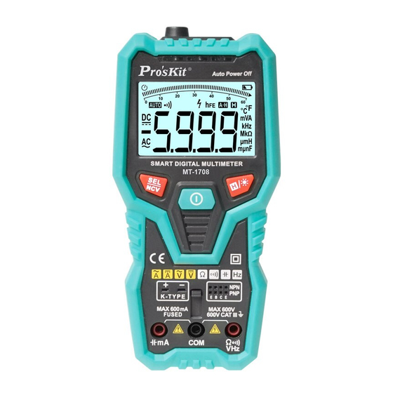
- Page 5 2.1 A Schematic diagram for the meter ① ⑥ ② ③ ⑦ ④ ⑧ ⑤ Physical appearance ①.NCV inductive probe ②. LCD display screen ③.Functional key ④.K-type thermocouple temperature probe socket ⑤ Input socket. ⑥.LED indicator ⑦ hFE Transistor testing socket ⑧ Toggle switch 2.2 Accessories Operation Manual Test lead...
- Page 6 Not: The instrument could not carry out measurement on two or more functions. Instrument's automatic detection sequence on measurement instrument: AC voltage → DC voltage → AC current → DC current → Temperature measurement → Transistor measurement → Capacitor measurement →...
- Page 7 When the measurement is completed, press the power key , to shut down the instrument power supply. Warning In order to avoid safety accidents such as potential electric shock or personal injury etc., please comply with safety work norms: 3.6 AC/DC Current/ Frequency / Capacitor measurement ...
- Page 8 It is not allowed to carry out measurement on electrified objects, or input measurement voltage of the socket from this. Pay attention to the polarity of the thermocouple, and do not reverse. Warning In order to avoid safety accidents such as potential electric shock or personal injury etc., please comply with safety work norms: 3.8 Transistor Measurement...
- Page 9 When the AC voltage sensed by the instrument is larger than about 90V, 4 green LED indicators and 2 red LED indicators will light up, meanwhile, the buzzer will send a "Di, Di" sound quickly. When the measurement is completed, press the power key shut down the instrument power supply.
- Page 10 Battery low voltage indication: When the battery voltage is lower than normal working voltage, " " will show on the display screen. Input polarity indication: It will display "-" automatically. Power supply: 3x1.5V AAA battery. Dimension:169mm x 83mm x 53mm 4.2 Accuracy specification The accuracy shall be applicable within one year after calibration.
- Page 11 4.2.5 Frequency Measuring range Resolution Accuracy 30Hz~1000 Hz 0. 1Hz ± (0.5% Reading + 2digits) Current channel: Sensitivity 5mA, measurement range 30~1000Hz Voltage channel: Sensitivity 0.5V measurement range 30~1000Hz Input protection: Max.600V DC or AC valid value. 4.2.6 Temperature Measuring range Resolution Accuracy -20 ~1300...
-
Page 12: Instrument Maintenance
Instruction: When the resistance is less than about 30, the built-in buzzer will sound, while the green LED indicator will light up; when the resistance is more than about 30 and less than about 50,the red LED indicator will light up, and the buzzer will not sound. 5 Instrument Maintenance This section provides the basic information on maintenance, including the descriptions about replacement of protective tubes and batteries. - Page 13 5.3 Fuse Replacement Only fuse with specified ampere, fuse rated value, voltage rated value and fusing speed could be used. To avoid any electric shock or personal injury, before opening the back cover or replacing the Fuse, please shut down and check to guarantee that the test lead has disconnected from the measurement circuit.
- Page 14 MT-1708 3-5/6 智能型數字電表說明書 概述 Pro’sKit MT-1708 3-5/6 智能型數字多用表是根據國際電工安全標準 IEC-61010 對 電子測量儀器和掌上型數位多用表的安全要求而設計生產的。 符合 IEC61010 的 600V CAT. Ⅲ和污染程度 2 要求。使用本儀錶前,請仔細閱讀使用說 明書並請注意有關安全工作準則。 安全資訊 安全說明 使用本儀錶時,使用者必須遵守關於以下兩方面的全部標準安全規範: A 防止電擊方面的安全規範 B 防止錯誤使用儀表方面的安全規範 C 為保證人身安全,請使用隨表提供的測試表棒。在使用前,檢查並確保表棒是完好的。 安全注意事項 在電磁干擾比較大的設備附近使用儀錶,儀錶的讀數會不穩定,甚至可能會 產生較大的誤差。 當儀錶或表棒外觀破損時,請不要使用。 若不正確使用儀錶,儀錶提供的安全功能可能會失效。 在裸露的導體或總線周圍工作時,必須極其小心。...
- Page 15 在進行電流測量前,應先檢查儀錶的保險管。在儀錶連接到被測電路之前, 應先將被測電路的電源關閉。 在進行電視機維修或測量電源轉換電路時,必須小心被測電路中的高幅電壓 脈衝以免損壞儀錶。 本儀錶使用 3 節 1.5V AAA 電池供電,電池必須正確安裝在儀錶的電池盒 內。 當電池欠壓符號 出現時,應立即更換電池。電池電量不足會使儀錶讀 數錯誤,從而可能導致電擊或人身傷害。 在進行測量類別.Ⅲ電壓測量時不可超過 600V。 儀錶的外殼(或外殼的一部分)被拆下時,切勿使用儀錶。 安全符號: 儀錶表體及使用說明書中使用的符號: 警告,重要的安全標誌,使用前應參閱使用說明書。錯誤使用可 能致設備或它的部件的損壞。 AC(交流) DC(直流) 交流電或直流電 接地 雙重絕緣保護 保險絲 符合歐盟(European Union)指令 高壓警告 CAT. III III 類 600V 過電壓保護 安全的保養習慣...
- Page 16 如果觀察到儀錶有任何異常, 該儀錶應立即停止使用並送維修。並確保在檢 查合格前不能被使用。 當長時間不用時,請將電池取下,並避免存放于高溫高濕的地方。 輸入保護措施 在進行電壓測量時,可承受最高輸入電壓是直流或交流電壓 600V。 在進行電電容、電流 mA 測量時,通過保險管(F630mA/250V)進行保護。 儀錶示意說明 本儀錶是一款具有真有效值的掌上型測量數位萬用表。具有大螢幕液晶數字顯示屏,並有 背光源,使用者容易讀數。具有超載保護和電池欠壓指示。無論專業人員、工廠、學校、 愛好者或家庭使用,均為一台理想的多功能儀錶。 儀表示意圖 ① 非接觸電壓感應探頭 ② 液晶顯示器 ③ 按鍵 ④ K 型熱電偶插座 ⑤ 輸入插座 ⑥ LED 指示燈 ⑦ hFE 電晶體測試插座 ⑧ 撥動開關 2.2 配件說明 說明書...
- Page 17 操作指南 本儀錶是一款智慧型數字多用表,所以使用操作非常簡單,測量時不需要進行功能選擇, 儀錶會自動識別測量信號,然後測量並顯示測量結果。 注意: 儀錶不可以同時進行兩種或多種功能測量。 儀錶對測量儀錶自動檢測的順序: 交流電壓→直流電壓→交流電流→直流電流→溫度測量→電晶體測量→電容測量→ 電阻及通斷 開機/關機 開機:儀錶在關機狀態下,按 鍵並保持,直到蜂鳴器“嘀”一聲,再鬆開。 關機:儀錶在開機狀態下,按 鍵並保持,直到蜂鳴器“嘀”一聲,再鬆開。 自動關機功能 開機約 10 分鐘後若無任何操作,儀錶會發出“滴-滴… … ”聲音提示,然後自動關機。 背光和照明功能 按 鍵約 2 秒開啟背光和照明燈;再按該鍵約 2 秒關閉背光和照明燈;或者開啟約 15 秒後自動關閉。 資料保持功能 按 鍵開啟資料保持,顯示屏顯示 字符;再按 鍵關閉資料保持。 交直流電壓/頻率/電阻測量/通斷測試...
- Page 18 測量電容時將表棒並聯到待測電容兩端;測量電流時串聯到待測電路。儀錶會自動識 別並測量信號。 從顯示屏讀取測量結果 。 測量直流電流時顯示屏同時顯示紅色表棒測試端的電流極性 測量交流電流時,按 鍵可顯示頻率,再 率鍵切換回交流電流顯示。 測量結束,按下電源鍵 ,關閉儀錶電源。 注意: 儀錶最大測量電流 600mA 最小測量電流 5mA 當測量大電容時,約需 10 秒才顯示測量結果。 : 為了避免可能的觸電或人身傷害等安全事故,請確實遵守安全工作規範 溫度測量 按下電源鍵 ,打開儀錶的電源。 取下表棒,將儀錶面板上的撥動開關輕輕的往下推,直到撥動開關被鎖住。 將 K 型熱電偶溫度探頭插入 K 型熱電偶溫度探頭插孔。 將熱電偶溫度探頭感應端貼近或緊貼被測量物件。...
- Page 19 NCV 檢測 按下電源鍵 ,打開儀錶的電源。 按下 鍵,並保持住,儀錶將顯示“NCV”。 然後將儀錶 NCV 感應探頭逐漸靠近被檢測點。 當儀錶感應到交流電壓大於約 12V 時將點亮 2 個綠色 LED 指示燈,同時蜂鳴發出慢 速的“嘀、嘀”提示音。 當儀錶感應到交流電壓大於約 60V 時將點亮 4 個綠色 LED 指示燈,同時蜂鳴發出中 速的“嘀、嘀”提示音。 當儀錶感應到交流電壓大於約 90V 時將點亮 4 個綠色 LED 指示燈和 2 個紅色 LED ...
- Page 20 電池低壓指示:當電池電壓低於正常工作電壓時,“ ”將顯示在顯示幕上。 輸入極性指示:自動顯示“”號 電源: 3x1.5V AAA 電池 外形尺寸:169mm x 83mm x 53mm 準確度指標 準確度在校準後一年內適用。 基準條件:環境溫度 18℃至 28℃、相對濕度不大於 80。 直流電壓 量程 解析度 準確度 0.001V 0.01V ±(0.8% 讀數 +3 字) 600V 0.1V 輸入阻抗:10MΩ 最小測量電壓:0.2V 直流電壓 最大測量電壓:600V DC 或 AC 有效值。 交流電壓...
- Page 21 交流電流 量程 解析度 準確度 600mA 0.1mA ±(1.5%讀數 +3 字) 最小測量電流:5mA 最大測量電流:600mA DC 或 AC 有效值。 輸入保護:630 mA /250V 保險管。 頻率範圍:45Hz~65Hz,真有效值響應。 頻率 量程 解析度 準確度 30~1000Hz 0.1Hz ±(0.5%讀數 +2 字) 電流通道:靈敏度 5mA,測量範圍 30~1000Hz 電壓通道:靈敏度 0.5V,測量範圍 30~1000Hz 輸入保護:最大 600V DC 或 AC 有效值。 溫度...
- Page 22 電容 量程 解析度 準確度 60nF 0.01nF 600nF 0.1nF 0.001uF ±(4.0% 讀數 +5 字) 60uF 0.01uF 600uF 0.1uF 0.001mF 輸入保護:F630mA/250V 保險管或 600V/PTC。 最小測量電容:1nF 通斷測試 功能 說明 測試環境 當內置蜂鳴器響時,被測 測試電流:約 0.6mA;開路電壓: 電阻小於約 30。 約 1.0V。 輸入保護:最大 600V DC 或 AC 有效值。 說明:電阻小於約...
- Page 23 為避免電擊或人身傷害,在打開電池蓋更換電池之前,應關機並檢查確保表棒已從測 量電路斷開。 請按照以下步驟更換電池(本儀錶使用 1.5V AAA 電池 x 3 個): 關斷儀錶電源。 將表棒與被測量電路斷開,並從儀錶移走。 用鑼絲刀旋松固定電池蓋的螺釘,取下電池蓋。 取下舊電池,換上新的電池。 裝上電池蓋,上緊螺釘 更換保險管 警告 只能使用指定的安培數,熔斷額定值,電壓額定值及熔斷速度的保險管 為避免電擊或人身傷害,在打開後蓋更換保險管之前,應關機並檢查確保表筆已從測 量電路斷開。 請按照以下步驟更換: 關斷儀錶電源。 將表棒與被測量電路斷開,並從儀錶移走。 用螺絲起子卸下固定後蓋的螺釘,取下後蓋。 取下舊的保險管,換上新的相同型號或規格(F630mA/250V)的保險管。 裝上後蓋,上緊螺釘 ...
- Page 24 MT-1708 3-5/6 智能型数字电表使用手册 1. 概述 Pro’sKit MT-1708 3-5/6 智能型数字多用表是根据国际电工安全标准 IEC- 61010 对电子测量仪器和掌上型数字多用表的安全要求而设计生产的。 符合 IEC61010 的 600V CAT. Ⅲ和污染程度 2 要求。使用本仪表前,请仔细阅读 使用说明书并请注意有关安全工作准则。 安全信息 安全说明 使用本仪表时,使用者必须遵守关于以下两方面的全部标准安全规程: A 防止电击方面的安全规程 B 防止错误使用仪表方面的安全规程 为保证人身安全,请使用随表提供的测试笔。在使用前,检查并确保它们是完 好的。 安全注意事项 在电磁干扰比较大的设备附近使用仪表,仪表的读数会不稳定,甚至可能会产 生较大的误差。 当仪表或表笔外观破损时,请不要使用。...
- Page 25 在进行电流测量前,应先检查仪表的保险管。在仪表连接到被测电路之前,应 先将被测电路的电源关闭。 在进行电视机维修或测量电源转换电路时,必须小心被测电路中的高幅电压脉 冲以免损坏仪表。 本仪表使用 3 节 1.5V AAA 电池供电,电池必须正确安装在仪表的电池盒内。 当电池欠压符号 出现时,应立即更换电池。 电池电量不足会使仪表读 数错误,从而可能导致电击或人身伤害。 在进行测量类别.Ⅲ电压测量时不可超过 600V。 仪表的外壳(或外壳的一部分)被拆下时,切勿使用仪表。 安全符号: 仪表表体及使用说明书中使用的符号: 警告,重要的安全标志,使用前应参阅使用说明书。错误使用可能 导致设备或它的部件的损坏。 AC(交流) DC(直流) 交流电或直流电 接地 双重绝缘保护 保险丝 符合欧盟(European Union)指令 高压警告 CAT. III III 类 600V 过电压保护 ...
- Page 26 2. 仪表示意说明 本仪表是一款具有真有效值的掌上型测量数字万用表。 具有大屏幕液晶数字显示屏, 并有背光源,使用者容易读数。具有超载保护和电池欠压指示。无论专业人员、工 厂、学校、爱好者或家庭使用,均为一台理想的多功能仪表。 2.1 仪表示意图 ①.非接触电压感应探头 ②. 液晶显示器 ③. 按键 ④. K 型热电偶插座 ⑤. 输入 插座 ⑥ LED 指示灯 . ⑦ hFE 晶体管测试插座 ⑧ 拨动开关 2.2 配件说明 说明书 X 1 本 测试表棒 X 1 对 K-Type 温度探棒 X 1 个...
- Page 27 3. 操作指南 本仪表是一款智能型数字多用表,所以使用操作非常简单,测量时不需要进行功能 选择,仪表会自动识别测量信号,然后测量并显示测量结果。 注意: 仪表不可以同时进行两种或多种功能测量。 仪表对测量仪表自动检测的顺序: 交流电压→直流电压→交流电流→直流电流→温度测量→晶体管测量→电容 测量→电阻及通断 开机/关机 开机:仪表在关机状态下,按 键并保持,直到蜂鸣器“嘀”一声,再松开。 关机:仪表在开机状态下,按 键并保持,直到蜂鸣器“嘀”一声,再松开。 自动关机功能 开机约 10 分钟后若无任何操作,仪表会发出“滴-滴……”声音提示,然后自动关 机。 背光和照明功能 按 键约 2 秒开启背光和照明灯;再按该键约 2 秒关闭背光和照明灯;或者开启 约 15 秒后自动关闭。 数据保持功能 按 键开启数据保持,显示屏显示 字符;再按 键关闭数据保持。...
- Page 28 测量电容时将表笔并联到待测电容两端;测量电流时串联到待测电路。仪表会 自动识别并测量信号。 从显示屏读取测量结果。测量直流电流时,显示屏同时显示红色表笔测试端的 电流极性。 测量交流电流时,按 键可显示频率,再 率键切换回交流电流显示。 测量结束,按下电源键 ,关闭仪表电源。 注意: 仪表最大测量电流 600mA 最小测量电流 5mA 当测量大电容时,约需 10 秒才显示测量结果。 :为了避免可能的触电或人身伤害等安全事故,请切实遵守安全 工作规范 温度测量 按下电源键 ,打开仪表的电源。 取下表笔,将仪表面板上的拔钮轻轻的往下推,直到拔钮锁住。 将 K 型热电偶温度探头插入 K 型热电偶温度探头插孔。 将热电偶温度探头感应端贴近或紧贴被测量物件。...
- Page 29 NCV 检测 按下电源键 ,打开仪表的电源。 按下 键,并保持住,仪表将显示“NCV” 。 然后将仪表 NCV 感应探头逐渐靠近被检测点。 当仪表感应到交流电压大于约 12V 时将点亮 2 个绿色 LED 指示灯,同时蜂鸣 发出慢速的“嘀、嘀”提示音。 当仪表感应到交流电压大于约 60V 时将点亮 4 个绿色 LED 指示灯,同时蜂鸣 发出中速的“嘀、嘀”提示音。 当仪表感应到交流电压大于约 90V 时将点亮 4 个绿色 LED 指示灯和 2 个红色 LED 指示灯,同时蜂鸣发出快速的“嘀、嘀”提示音。...
- Page 30 电池低压指示:当电池电压低于正常工作电压时, “ ”将显示在显示屏上。 输入极性指示:自动显示“”号 电源: 3x1.5V AAA 电池 外形尺寸:169mm x 83mm x 53mm 5. 准确度指标 准确度在校准后一年内适用。 基准条件:环境温度 18℃至 28℃、相对湿度不大于 80。 直流电压 量程 分辨率 准确度 0.001V 0.01V ±(0.8% 读数 +3 字) 600V 0.1V 输入阻抗:10MΩ 最小测量电压:0.2V 直流电压 最大测量电压:600V DC 或...
- Page 31 最大测量电流:600mA DC 或 AC 有效值。 输入保护:F630mA/250V 保险管。 频率范围:45Hz~65Hz,真有效值响应。 频率 量程 分辨率 准确度 30~1000Hz 0.1Hz ±(0.5%读数 +2 字) 电流通道:灵敏度 5mA,测量范围 30~1000Hz 电压信道:灵敏度 0.5V,测量范围 30~1000Hz 输入保护:最大 600V DC 或 AC 有效值。 温度 量程 分辨率 准确度 -20~1300℃ 1℃ ±(1.0%读数 + 3 字) -4°F~2372°F 1°F ±(0.5%读数...
- Page 32 电容 量程 分辨率 准确度 60nF 0.01nF 600nF 0.1nF 0.001uF ±(4.0% 读数 +5 字) 60uF 0.01uF 600uF 0.1uF 0.001mF 输入保护:F630mA/250V 保险管或 600V/PTC。 最小测量电容:1nF 通断测试 功能 说明 测试环境 当内置蜂鸣器响时,被 测试电流:约 0.6mA;开路电 测电阻小于约 30。 压:约 1.0V。 输入保护:最大 600V DC 或 AC 有效值。 说明:电阻小于约...
- Page 33 为避免电击或人身伤害,在打开电池盖更换电池之前,应关机并检查确保表笔 已从测量电路断开。 请按照以下步骤更换电池: 关断仪表电源。 将表笔与被测量电路断开,并从仪表移走。 用 PH1 十字螺丝刀旋松固定电池盖的螺钉,取下电池盖。 取下旧电池,换上新的电池。 装上电池盖,上紧螺钉 更换保险管 警告 只能使用指定的安培数,熔断额定值,电压额定值及熔断速度的保险管 为避免电击或人身伤害,在打开后盖更换保险管之前,应关机并检查确保表笔 已从测量电路断开。 请按照以下步骤更换: 关断仪表电源。 将表笔与被测量电路断开,并从仪表移走。 用 PH1 十字螺丝刀旋松固定后盖的螺钉,取下后盖。 取下旧的保险管,换上新的相同型号或规格(F630mA/250V)的保险管。 装上后盖,上紧螺钉...
- Page 34 中国地区产品保固卡 店章 购买日期 公司名称 联络电话 电子邮箱 联络地址 产品型号 □ MT-1708 ※ 在正常使用情况下,自原购买日起 12 个月免费维修保证(不含耗材、 消耗品) 。 ※ 产品保固卡需盖上店章、日期章,其保固效力始生效。 ※ 本卡请妥善保存,如需维修服务时,请出示本卡以为证明。 ※ 保固期满后,属调整、保养或是维修性质之服务,则酌收检修工时费 用。若有零件需更换,则零件费另计。 产品保固说明 保固期限内,如有下列情况者,维修中心则得酌收材料成本或修理费 (由本公司维修人员判定): • 对产品表面的损伤,包括外壳裂缝或刮痕 • 因误用、疏忽、不当安装或测量,未经授权打开产品修理,修改产品 或者任何其它超出预期使用范围的原因所造成的损害 • 因事故、火灾、电力变化、其它危害,或自然灾难所造成的损害。 非服务保证内容: • 本体外之消耗品:如电池...等消耗品 • 本体之外附配件:如表笔、感温探头等附配件。...
- Page 35 制造商:宝工实业股份有限公司 地 址:台湾台北新北市新店区民权路 130 巷 7 号 5 楼 电 话:886-2-22183233 E-mail: pk@mail.prokits.com.tw 生产商:上海宝工工具有限公司 地址:上海市浦东新区康桥东路1365弄25号 原产地:中国 上海 销售公司:深圳畅联贸易有限公司 地址:深圳市福田区红荔西路上步工业区403栋东座5楼 电话:0755-83692415 传真:0755-83692143 400服务热线:400-1699-629...
Need help?
Do you have a question about the MT-1708 and is the answer not in the manual?
Questions and answers
How to test diod with mt-1708 please