
Related Manuals for Thermal Dynamics cutskill 35A


Summary of Contents for Thermal Dynamics cutskill 35A
- Page 1 cutskill ™ plasma cutting system Art # A-09203 Operating manual Rev. AA Issue Date: June 30, 2009 Manual # 0-5063 Operating Features: PHASE...
- Page 2 WE APPRECIATE YOUR BUSINESS! Congratulations on your new Thermal Dynamics product. We are proud to have you as our customer and will strive to provide you with the best service and reliability in the industry. This product is backed by our extensive warranty and world-wide service network. To locate your nearest distributor or service provider visit us on the web at www.cigweld.com.au (Asia Pacific) www.thermal- dynamics.com (Americas and Europe). This Operating Manual has been designed to instruct you on the correct use and operation of your Thermal Dynamics product. Your satisfaction with this product and its safe operation is our ultimate concern. Therefore please take the time to read the entire manual, especially the Safety Precautions. They will help you to avoid po- tential hazards that may exist when working with this product. YOU ARE IN GOOD COMPANY! The Brand of Choice for Contractors and Fabricators Worldwide. Thermal Dynamics is a Global Brand of manual and automation Plasma Cutting Products for Thermadyne Industries Inc. We distinguish ourselves from our competition through market- leading, dependable products that have stood the test of time.
- Page 3 WARNINGS Read and understand this entire Manual and your employer’s safety practices before installing, operating, or servicing the equipment. While the information contained in this Manual represents the Manufacturer's best judgement, the Manufacturer assumes no liability for its use. Plasma Cutting Power Supply CutSkill™ 35A SL60 1Torch™ Operating Manual Number 0-5063 Published by: Thermal Dynamics Corporation 82 Benning Street West Lebanon, New Hampshire, USA 03784 (603) 298-5711 www.thermal-dynamics.com Copyright 2009 by Thermadyne Corporation All rights reserved. Reproduction of this work, in whole or in part, without written permission of the publisher is prohibited. The publisher does not assume and hereby disclaims any liability to any party for any loss or damage caused by any error or omission in this Manual, whether such error results from negli- gence, accident, or any other cause. Publication Date: June 30, 2009 Record the following information for Warranty purposes: W here Purchased:_______________________________ ____________ P urchase Date:__________________________________ _ ___________ P ower Supply Serial #:___________________________ _ ____________...
-
Page 4: Table Of Contents
TABLE OF CONTENTS SECTION 1: GENERAL INFORMATION ....................... 1-1 1.01 Notes, Cautions and Warnings ................. 1-1 1.02 Important Safety Precautions ................... 1-1 1.03 Publications ......................1-3 1.04 Declaration of Conformity ..................1-4 1.05 Statement of Warranty ..................... 1-5 SECTION 2 SYSTEM: INTRODUCTION ..................... 2-1 2.01 Working Principle ..................... -
Page 5: Section 1: General Information
cutskill 35A SECTION 1: Antimony Chromium Mercury Arsenic Cobalt Nickel GENERAL INFORMATION Barium Copper Selenium Beryllium Lead Silver Cadmium Manganese Vanadium • Always read the Material Safety Data Sheets (MSDS) that 1.01 Notes, Cautions and Warnings should be supplied with the material you are using. These Throughout this manual, notes, cautions, and warnings are used to MSDSs will give you the information regarding the kind and highlight important information. - Page 6 cutskill 35A • Keep helmet and safety glasses in good condition. Replace lenses when cracked, chipped or dirty. • Protect others in the work area from the arc rays. Use protec- NOISE tive booths, screens or shields. Noise can cause permanent hearing loss. Plasma arc processes can cause noise levels to exceed safe limits.
-
Page 7: Publications
cutskill 35A 9. NFPA Standard 70, NATIONAL ELECTRICAL CODE, obtain- 1.03 Publications able from the National Fire Protection Association, Bat- Refer to the following standards or their latest revisions for more terymarch Park, Quincy, MA 02269 information: 10. NFPA Standard 51B, CUTTING AND WELDING PROCESSES, 1. -
Page 8: Declaration Of Conformity
cutskill 35A 1.04 Declaration of Conformity Manufacturer: Thermadyne Company Address: 82 Benning Street West Lebanon, New Hampshire 03784 The equipment described in this manual conforms to all applicable aspects and regulations of the ‘Low Voltage Directive’ (European Council Directive 73/23/EEC as amended by Council Directive 93/68/EEC) and to the National legislation for the enforcement of this Directive. The equipment described in this manual conforms to all applicable aspects and regulations of the "EMC Directive"... -
Page 9: Statement Of Warranty
LIMITED WARRANTY: Subject to the terms and conditions established below, Thermadyne Company warrants to the original retail purchaser that new Thermal Dynamics CUTSKILL™ plasma cutting systems sold after the effective date of this warranty are free of defects in material and workmanship. -
Page 11: Section 2 System: Introduction
2.02 Power Supply Specifications CutSkill 35A Power Supply Specifications Input Power 220-240 VAC (± 15%), Single-Phase, 50 Hz Output Current 15-35 Amps, continuously variable CutSkill 35A Power Supply Duty Cycle (Note 1) Ambient Temperature 104° F (40° C) Duty Cycle Current 35 Amps SL 60 Torch Gas Requirements (see section 2T.03) -
Page 12: Input Wiring Specifications
CAUTION Provide clearance for proper air flow through the power supply. Operation without proper air flow will inhibit proper cooling and reduce duty cycle. 2.03 Input Wiring Specifications CutSkill 35A Input Power Requirements Suggested Sizes Input Power Input Current Input... -
Page 13: Power Supply Features
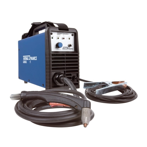
35a 2.04 Power Supply Features 240V AC Power Source Gas Pressure Regulator/ Filter Assembly Control Panel Work Cable and Clamp Torch Lead Art # A-09175 Gas Pressure Regulator/ Filter Assembly Gas Pressure Gauge Art # A-09176 June 30, 2009... - Page 14 This Page left blank intentionally.
-
Page 15: Section 2 Torch: Introduction
35a SECTION 2 TORCH: F. Torch Ratings INTRODUCTION SL60 Torch Ratings Ambient 104° F Temperature 40° C 2T.01 Scope of Manual Duty Cycle 100% @ 60 Amps @ 400 scfh Maximum Current 60 Amps This manual contains descriptions, operating instruc-... -
Page 16: 03 Introduction To Plasma
CUTSkILL 35A 2T.03 Introduction to Plasma B. Gas Distribution The single gas used is internally split into plasma A. Plasma Gas Flow and secondary gases. Plasma is a gas which has been heated to an The plasma gas flows into the torch through the... -
Page 17: Unpacking
35a SECTION 3: INSTALLATION 3.01 Unpacking 1. Use the packing lists to identify and account for each item. A. Contents List Description Quantity Power source 3 m power input cable (fitted) SL60 1 Torch (fitted) Work cable and clamp (fitted) -
Page 18: Air Supply Connections
35a Power Cord and Plug This power supply includes an input power cord and plug suitable for 240 VAC, 15 Amp, Single - Phase input power. 240V AC Power Source Art # A-09177 Figure 3-1 240V AC Power Source When the power source input voltage is over or under the safe operating range, the alarm light will turn on, at the same time the current output will be cut off. -
Page 19: Gas Connections
35a Adjustment knob of compressed air Pressure Fitting Compressed air input Hose Clamp Compressed air Gas Supply Hose pressure meter Air filter Art # A-09178 Figure 3-2 Gas Connection to Compressed Air input B. Using Industrial Compressed Air In Gas Cylinders When using Industrial compressed air in gas cylinders as the gas supply: 1. - Page 20 This page left blank intentionally.
-
Page 21: Section 4 System: Operation
35A SECTION 4 SYSTEM: OPERATION 4.01 Control Panel Adjustment knob Air Indicator of compressed Over Heat Indicator Power switch air Pressure Power cable Compressed POWER OVERHEAT READY input Power On Indicator DC Indicator air input Run/Set Switch Compressed air... -
Page 22: Preparations For Operating
Check the torch for proper assembly and appropriate torch parts. The torch parts must correspond with the type of operation, and with the amperage output of this power supply (35 amps maximum). Use only genuine Thermal Dynamics parts with this torch. Art # A-03409_AB Large O-Ring, Cat. - Page 23 35A C. Check Primary Input Power Source 1. Check the power source for proper input voltage. Make sure the input power source meets the power requirements for the unit per Section 2, Specifications. 2. Connect the input power cable (or close the main disconnect switch) to supply power to the system.
-
Page 24: Sequence Of Operation
35A Gas Pressure Regulator/ Filter Assembly Gas Pressure Gauge Art # A-09176 H. Select Current Output Level Place RUN / SET switch to RUN (up) position. Gas flow will stop. Set the desired current output level. Art # A-09181... - Page 25 35A NOTE Torch Minimum pressure for power supply op- eration is lower than minimum pressure for torch operation. 4. Wear protective clothing, including welding gloves and appropriate eye protection (see table 1-1). Place tip on work piece and pull trigger.
- Page 26 35A C. Keep the torch in contact with the workpiece C. Cut as usual. Simply release the trigger during the cutting cycle. assembly to stop cutting. D. Hold the torch away from your body. D. Follow normal recommended cutting E.
-
Page 27: Cut Quality
35A Bevel Angle 7. Set the power supply ON / OFF switch to OFF (down position). The angle between the surface of the cut edge and a. AC indicator turns OFF. a plane perpendicular to the surface of the plate. -
Page 28: General Cutting Information
35A 4.05 General Cutting Information Left Side Cut Angle Right Side Cut Angle WARNING Disconnect primary power at the source be- fore disassembling the power supply, torch, or torch leads. Frequently review the Important Safety Pre- A-00512 cautions at the front of this manual. Be sure... -
Page 29: Section 5 System: Service
35a SECTION 5 SYSTEM: SERVICE 5.01 General Maintenance Warning! There are extremely dangerous voltage and power levels present inside this product. Do not attempt to open or repair unless you are a qualified electrical tradesperson and you have had training in power measurements Maintain more often and troubleshooting techniques. -
Page 30: Basic Troubleshooting Guide
35a A. Every three months Check external air filter, replace if necessary. 1. Shut off input power; turn off the gas supply. Bleed down the gas supply. Check air filter and replace if neces- sary. NOTE Leave internal ground wire in place. - Page 31 35a Faulty components in unit Return for repair or have qualified technician repair per service manual. E. Torch will not pilot, when torch trigger is activated. The system is in SET mode. Switch to RUN mode. Art # A-03640...
- Page 32 35a Faulty components in unit Return for repair or have qualified technician repair per service manual. I. Cutting output is unstable or inadequate. Input or output connection is poor Check all input and output connection leads. Working cable connection is poor.
-
Page 33: Section 5 Torch: Service
35A SECTION 5 TORCH: NOTE SERVICE The shield cup holds the tip and starter cartridge shield cup in place. Position the torch with the shield cup facing upward to 5T.01 General Maintenance prevent these parts from falling out when NOTE the cup is removed. - Page 34 35A Spring-Loaded Spring-Loaded Lower End Fitting Lower End Fitting at Reset / Full Compression 1/8”(3mm) Full Extension Art # A-08064_AB 5. Pull the electrode straight out of the torch head. Check the face of the electrode for excessive wear. Refer to the following figure.
-
Page 35: Section 6: Parts Lists
35a SECTION 6: PARTS LISTS 6.01 Introduction A. Parts List Breakdown The parts list provides a breakdown of all replaceable components. Item # Description Catalog # Logic PCB assembly 9-0134 Control PCB assembly 9-0135 Main PCB assembly 9-0137 Regulator... - Page 36 This page left blank intentionally.
-
Page 37: Appendix 1: Circuit Diagram
35a APPENDIX 1: CIRCUIT DIAGRAM Art # A-09193_AB June 30, 2009 Appendix... - Page 38 This page left blank intentionally.
- Page 39 GLOBAL CUSTOMER SERVICE CONTACT Thermadyne USA Thermadyne Asia Sdn Bhd 2800 Airport Road Lot 151, Jalan Industri 3/5A Denton, Tx 76207 USA Rawang Integrated Industrial Park - Jln Batu Arang Telephone: (940) 566-2000 48000 Rawang Selangor Darul Ehsan 800-426-1888 West Malaysia Fax: 800-535-0557 Telephone: 603+ 6092 2988 Fax : 603+ 6092 1085...
- Page 40 Asia Pacific Regional Headquarters 71 Gower Street Preston, Victoria, Australia, 3072 Telephone: +61 3 9474 7400 Fax: +61 3 9474 7488 Email: cigweldsales@cigweld.com.au...
Need help?
Do you have a question about the cutskill 35A and is the answer not in the manual?
Questions and answers