
Related Manuals for Thermal Dynamics Ultra-cut 300


Summary of Contents for Thermal Dynamics Ultra-cut 300
- Page 1 ™ ULTRA-CUT PLASMA CUTTING SYSTEM Art # A-04816 Operating Manual Rev. AG.01 Date: July 10, 2007 Manual # 0-4819 Operating Features:...
- Page 2 This Operating Manual has been designed to instruct you on the cor- rect use and operation of your Thermal Dynamics product. Your satis- faction with this product and its safe operation is our ultimate concern.
- Page 3 WARNINGS Read and understand this entire Manual and your employer’s safety practices before installing, operating, or servicing the equipment. While the information contained in this Manual represents the Manufacturer's best judge- ment, the Manufacturer assumes no liability for its use. Plasma Cutting Power Supply, Ultra-Cut ®...
- Page 4 This page intentionally blank...
-
Page 5: Table Of Contents
TABLE OF CONTENTS SECTION 1: GENERAL INFORMATION ....................1-1 1.01 Notes, Cautions and Warnings ..............1-1 1.02 Important Safety Precautions ............... 1-1 1.03 Publications ....................1-3 1.04 Declaration of Conformity ................1-5 1.05 Statement of Warranty .................. 1-6 SECTION 2: SPECIFICATIONS ....................2-1 General Description Of The System .............. - Page 6 TABLE OF CONTENTS (continued) SECTION 4: OPERATION ......................4-1 Power Supply Control Panel .................. 4-1 Start-Up Sequence ....................4-2 Gas Control Module Operation ................4-3 Sequence Of Operation ..................4-7 Gas Selection ...................... 4-10 Power Supply Status Codes ................4-11 Remote Arc Starter: Service Chart ..............
- Page 7 TABLE OF CONTENTS (continued) SECTION 7: TORCH MAINTENANCE ..................7-1 Consumable Removal ................... 7-1 O-Ring Lubrication ..................7-2 Parts Wear ....................7-2 Torch Consumables Installation ..............7-3 Coolant Leak Trouble-Shooting ..............7-5 APPENDIX 1: Remote Arc Starter Schematic ................A-1 APPENDIX 2: Gas Control and Torch Valve Schematic .............
- Page 8 TABLE OF CONTENTS (continued)
-
Page 9: General Information
SECTION 1: GENERAL INFORMATION 1.01 Notes, Cautions and Warnings Throughout this manual, notes, cautions, and warnings are used to highlight important information. These highlights are categorized as follows: NOTE An operation, procedure, or background information which requires additional emphasis or is helpful in efficient operation of the system. - Page 10 • Always read the Material Safety Data Sheets (MSDS) that should be supplied with the material you are using. These MSDSs will give you the information regarding the kind and amount of fumes and gases that may be dangerous to your health. •...
-
Page 11: 1.03 Publications
PLASMA ARC RAYS Plasma Arc Rays can injure your eyes and burn your skin. The plasma arc process produces very bright ultra violet and infra red light. These arc rays will damage your eyes and burn your skin if you are not properly protected. •... - Page 12 13. NWSA booklet, WELDING SAFETY BIBLIOGRAPHY obtainable from the National Welding Supply Association, 1900 Arch Street, Philadelphia, PA 19103 14. American Welding Society Standard AWSF4.1, RECOMMENDED SAFE PRACTICES FOR THE PREPARATION FOR WELDING AND CUTTING OF CONTAINERS AND PIPING THAT HAVE HELD HAZARDOUS SUBSTANCES, obtainable from the American Welding Society, 550 N.W.
-
Page 13: 1.04 Declaration Of Conformity
Rigorous testing is incorporated into the manufacturing process to ensure the manufactured product meets or exceeds all design specifications. Thermal Dynamics has been manufacturing products for more than 30 years, and will continue to achieve excellence in our area of manufacture. -
Page 14: 1.05 Statement Of Warranty
90 Days Warranty repairs or replacement claims under this limited warranty must be submitted by an authorized Thermal Dynamics® repair facility within thirty (30) days of the repair. No transportation costs of any kind will be paid under this warranty. Transportation charges to send products to an authorized warranty repair facility shall be the responsibility of the customer. -
Page 15: Section 2: Specifications
SECTION 2: SPECIFICATIONS General Description Of The System A typical Ultra-Cut ® 300 system configuration includes: • One Power Supply • Remote Arc Starter • Gas Control Module • Torch Valve Assembly • Precision Plasma Cutting Torch • Set Of Connecting Leads •... -
Page 16: Specifications & Electrical Requirements
Specifications & Electrical Requirements Ultra-Cut 300 Specifications & Design Features Max OCV (U 380 vdc Minimum Output Current 10 Amps Max Output Current 300 Amps Output Voltage 60 - 230 vdc Duty Cycle Rating 100% @ 300A, 180V, (54kW), Ambient Temperature 104F°... -
Page 17: Power Supply Dimensions
Power Supply Dimensions 27 inch 680 mm 52.25 inch 1030 mm 33 inch 27.5 inch 840 mm 700 mm 37.75 inch 960 mm 535 lb / 243 kg Art # A-06939 Manual No. 0-4819 SPECIFICATIONS... -
Page 18: Power Supply Rear Panel Features
Power Supply Rear Panel Features Torch (Neg) Terminal AC Power Lamp Pilot (Pos) Terminal Input Power Circuit Breaker Terminals Panel Ground Terminals Gas Control Console Connector Terminal Cover CNC Connector Work Cable Terminal Remote Arc Starter Connector Terminal Cover Support Panel RETURN SUPPLY Coolant Connections... -
Page 19: Gas Requirements
The customer will provide all gases and pressure regulators. Gases must be of high quality. Pressure regulators shall be double stage and installed within 3 meters from the Gas Console. Ultra-Cut 300 Power Supply: Gas Pressures, Flows, and Quality Requirements Quality... -
Page 20: Xttm-300 Torch Specifications
-300 Torch Specifications A. Torch Dimensions Art # A-04897 19.00" 2.25" 482.68 mm 57.15 mm 2.0" 15.50" 50.8 mm 393.78 mm 6.30" 160.10 mm 2.39" 60.81 mm 3.54" 89.87 mm 2.74" 69.55 mm 1.57" 39.96 mm 1.49" 37.8 mm Manual No. 0-4819 SPECIFICATIONS... - Page 21 B. Torch Leads Lengths Gas Lead Assemblies Length Feet Meters 3.05 15.2 22.8 30.4 38.2 45.7 53.3 C. Torch Parts (Generic Parts Shown) Art # A-04741 Plasma Gas Shield Gas Distributor Distributor Shield Cap Electrode Shield Cup Cartridge D. Parts - In - Place (PIP) The torch is designed for use with a power supply which senses coolant return flow to confirm that torch parts are in place.
- Page 22 F. XT -300 Torch Data (with Ultra-Cut 300 Power Supply) -300 Torch Ratings for use with Ultra-Cut 300 Power Supply Ambient 104° F Temperature 40° C Duty Cycle 100% @ 300 Amps Maximum Current 300 Amps Voltage (V 500V peak...
-
Page 23: Section 3: Installation
Cooling System Requirements Coolant must be added to the system on installation. The amount required varies with torch leads length. Thermal Dynamics recommends the use of its coolants 7-3580 and 7-3581 (for low temperatures). Coolant Capabilities Cat. Number and Mixture... -
Page 24: System Layout
System Layout 25’ / 7.6 m Maximum Length 125’ / 38.1 m Maximum Length Pilot Return Pilot Return Negative Leads (2) Shield Remote Coolant Supply Coolant Supply w/ Negative 300-A Starter Power Coolant Return Coolant Return Supply Primary power Control Cable Ground Cable Shield Fiber... -
Page 25: Cables & Leads Identification
Cables & Leads Identification #8 AWG Cable Pilot Return, Power Supply to Arc Starter #1 AWG Cable Negative Lead, Power Supply to Arc Starter Coolant Supply Lead, Green Green Power Supply to Arc Starter Coolant Return Lead, Power Supply to Arc Starter Control Cable, Power Supply to Arc Starter Ground Cable... -
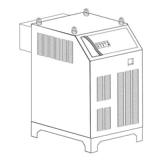
Page 26: Lift The Power Supply
Lift the Power Supply WARNINGS Do not touch live electrical parts. Disconnect input power conductors from de-energized supply line before moving unit. FALLING EQUIPMENT can cause serious personal injury and equipment damage. Use all four lifting eyes when using lifting straps to lift the power supply. Use a forklift, crane, or hoist to lift the unit off the shipping pallet as shown. -
Page 27: E -1. Set Switches On The Command - Control Module (Type 1 Module)
E -1. Set Switches on the Command - Control Module (Type 1 Module) Compare the command - control module to the illustration. Follow instructions in this section for a module with an external connection cover. Remove the power supply right side. Set switches on the CCM (Command-Control Module) per the illustrations. Switch settings and connection details are provided in the Appendix. - Page 28 CAUTION Printed circuit boards in the Command - Control Module are static - sensitive. Discharge any built-up static charges in your body or surroundings before touching the printed circuit boards. SW11 SW12 Art # A-07673 SW13 SW6: OK-to-Move: Contact closure, 120VAC @ 1A (Factory default setting) or DC Volts (16-18vdc@ up to 100 ma.) SW11: Analog Current Control.
-
Page 29: E -2. Set Switches On The Command - Control Module (Type 2 Module)
E -2. Set Switches on the Command - Control Module (Type 2 Module) Compare the command - control module to the illustration. Follow instructions in this section for a module without an external connection cover. Remove the power supply right side. Set switches on the CCM (Command-Control Module) per the illustrations. Switch settings and connection details are provided in the Appendix. - Page 30 CAUTION Printed circuit boards in the Command - Control Module are static - sensitive. Discharge any built-up static charges in your body or surroundings before touching the printed circuit boards. SW11 No external connection cover SW12 SW13 SW-6: OK-to-Move: Contact closure, 120VAC @ 1A (Factory default setting) or DC Volts (16-18vdc@ up to 100 ma.) SW-11: Analog Current Control.
-
Page 31: Remove The Connections Cover
Remove the Connections Cover The primary power cable must be supplied by the end user and connected to the power supply. Remove the connections cover on the rear of the Power Supply. Use caution when removing the panel; there is a ground wire connected to the inside of the panel. -
Page 32: Connect Work Cable And Pilot And Negative Leads
Connect Work Cable and Pilot and Negative Leads 1. Pass the ends of the work cable and pilot and negative leads upward through the leads bracket and then upward through openings in the connections cover support panel. 2. Refer to the illustration. Connect the leads as shown. Tighten securely. Do not overtighten. CAUTIONS The clear connections cover must remain in place. -
Page 33: Check / Adjust Input Voltage Configuration
Check / Adjust Input Voltage Configuration 1. The power supply includes a voltage configuration board which must be positioned to match the primary input voltage. Remove the power supply left side panel and locate the voltage configuration board. The input voltage configuration is shown at the top of the board. -
Page 34: Connect Input Power And System Ground Cables
Connect Input Power and System Ground Cables 1. Carefully cut back the outer sheath on the primary input power cable to expose the individual cords. Cut back the insulation on the individual cords. Route the cable upward through the leads bracket and through the connections cover support panel on the rear panel of the power supply. -
Page 35: Ground Connections
For Thermal Dynamics components (except Remote Arc Starter and Gas Control Module) it is recommended to use a minimum of 10 AWG (European 6 mm ) wire or flat copper braid with cross section equal to or greater than 10 AWG connected to the cutting table frame. - Page 36 C. Creating An Earth Ground 1. To create a solid, low resistance, earth ground, drive a 1/2 in (12 mm) or greater diameter copper clad ground rod at least 6 - 8 ft (1.8 - 2.4 m) into the earth so that the rod contacts moist soil over most of its length. Depending on location, a greater depth may be required to obtain a low resistance ground (see NOTE).
-
Page 37: Connect Coolant Leads
D. Routing Of Torch Leads 1. To minimize RF interference, position torch leads as far as possible from any CNC components, drive motors, control cables, or primary power lines. If cables have to pass over torch leads, do so at an angle. Do not run the plasma control or other control cables in parallel with the torch leads in power tracts. -
Page 38: Connect Control Cables For Cnc, Remote Arc Starter, And Gcm
Connect Control Cables for CNC, Remote Arc Starter, and GCM 1. Connect one end of each cable to the power supply. 2. Connect the other end of the CNC cable to the CNC device. 3. The CNC cable shield must be attached to ground at the CNC end of the cable. Do not ground to the Plasma Power Supply. - Page 39 A. Connect Fiber Optic Cable (Type 1 internal control module) CAUTION Check the type of internal control module. Use this section for connections to an internal control module with an external connections cover. Use the following section for connections to an internal control module without an external connections cover.
- Page 40 B. Connect Fiber Optic Cable (Type 2 internal control module) CAUTION Check the type of internal control module. Use this section for connections to an internal control module without an external connections cover. Use the preceding section for connections to an internal module with an external connections cover.
-
Page 41: Gas Control Module Installation
Gas Control Module Installation The Gas Control Module must be installed in a suitable location where it is easily accessible to the system operator. The unit must be mounted to a flat horizontal surface. If the Module is mounted to a gantry or to any other support subject to vibration or motion, the installer must fasten the module to the support securely. -
Page 42: Fiber Optic Cable Installation
Preparation 1. Remove the screws securing the Cover Panel to the Module. 2. Carefully remove the cover from the module noting the attached ground wire. Remove the ground wire if needed. Gas Control Module Cover Remove Ground Wire Do not remove Art # A-06882 Cover Removal Fiber Optic Cable Installation... - Page 43 Circuit Board Fiber Optic Cable J 5 6 J 5 7 P O W P L Y S U P T V A F L O H 3 5 P R E U T S P L A IN P A IR S H IE J5 6...
- Page 44 Circuit Board Fiber Optic Cable Art # A-04773 4. Tighten the through-hole protector for the fiber-optic cable. 5. Reinstall the Cover Panel making sure the ground wire is attached. Manual No. 0-4819 3-22 INSTALLATION...
-
Page 45: Gas Control Module: Control, Input, And Output Connections
Gas Control Module: Control, Input, and Output Connections 1. Make all other connections to the rear of the Module. The connections are labeled. The Module must be grounded; the grounding terminal is marked Use #10 AWG (European 6 mm ) (or thicker) wire for grounding. -
Page 46: Install Remote Arc Starter
Install Remote Arc Starter Site Location Select a clean, dry location with good ventilation and adequate working space around all components. Review the safety precautions in the front of this manual to be sure that the location meets all safety requirements. Interconnecting cables and hoses attach to the Arc Starter. - Page 47 2. Remove the Cover Panel from the Arc Starter. Upper screws (4 per side) Cover Ground Wire Lower screws Art # A-07029 3. Position the Arc Starter on a flat, horizontal mounting surface. 4. Use pre-drilled holes in at least two of the feet on the bottom of the Arc Starter to secure the Arc Starter to the mounting surface.
- Page 48 Art # A-04750 Coolant Supply and Return Hoses (from power supply) Coolant Return Green (Red) Coolant Supply (Green) Art # A-04751 Coolant Return (Red) Manual No. 0-4819 3-26 INSTALLATION...
- Page 49 Art # A-04752 Negative Cable from power supply Art # A-04754 Negative Cable (for > 150 Amps) Negative Cables (from Power Supply rear panel) Manual No. 0-4819 3-27 INSTALLATION...
- Page 50 Art # A-04753 Pilot Return Cable from Power supply PILOT Return Cable (from Power Supply rear panel) Art # A-04755 Control Cable from Power Supply rear panel Manual No. 0-4819 3-28 INSTALLATION...
- Page 51 Output Connections 1. Refer to the illustrations. Make the following output connections to the Arc Starter. Inner Shield Lead Pilot Lead Inner Shield Connection Detail Art # A-04933 Pilot Lead Connection Detail Pilot Return Cable and Inner Shield Lead (from Torch Leads) Art # A-04757 Some items are removed for clarity.
- Page 52 Reinstall the Arc Starter Cover. Ensure that the hardware at the cover grounding area is arranged as shown. Upper screws (4 per side) Cover Ground Wire Lower screws Art # A-07029 The Arc Starter must be grounded; the grounding terminal is marked .
- Page 53 • Use a clamp to secure the Torch Lead Shield braid to the port on the Remote Arc Starter as shown. Art # A-04759 Torch Leads Shield Shield Clamp Coolant and Pilot Leads to Torch Valve Assembly Manual No. 0-4819 3-31 INSTALLATION...
- Page 54 Connect Control Cable 1. Connect the Remote Arc Starter cable to the Remote Arc Starter receptacle. Power Supply Rear Panel RETURN SUPPLY COOLANT RETURN SUPPLY Remote Arc Starter Remote Arc Starter - Input Connection Panel Art # A-04801 Manual No. 0-4819 3-32 INSTALLATION...
-
Page 55: Original & Xtl Torch Valve Installation
Original & XTL Torch Valve Installation General Information This assembly mounts as close as possible to the torch head. It accepts preflow, plasma, and shield gases from the Gas Control Module and supplies these gases to the Torch. Mounting 113.03 mm 4.450”... -
Page 56: Connecting Torch
3. Connect the gas supply lines and the control cable connector from the Gas Control Module to the Valve Kit as shown. Hold the check valves stationary while attaching the gas lines. (XTL shown) Exhaust Muffler Control Cable Water Inlet Shield Gas Inlet Preflow Gas Inlet Plasma Gas Inlet... - Page 57 Coolant Supply, Coolant Return, and Pilot Leads Leads Cover Torch Leads End Cap Shield Gas (Right Hand Thread) Groove for O-Ring Pilot Lead O-Ring Mounting Tube To Torch Valve Plasma Gas (Left Hand Thread) Coolant Supply & Power Lead (-) Pilot Lead Connector Torch Head Assembly Art # A-04746...
-
Page 58: Install Consumable Torch Parts
Slowly apply pressure to the gas lines. Check for leaks at all connections before continuing. If there are no leaks, shut off the gas supplies and continue with installation. 7. Connect the pilot lead to the Torch Head. Press the two ends of the connector firmly together. Thread the plastic lead cover/connector onto the mating Torch Head connector. - Page 59 CAUTION Do not force the cartridge if it will not fully tighten. Remove the cartridge and gently clean the threads on the torch head body with a wire brush. Apply oxygen-compatible lubricant (supplied with the torch) to the threads. Manual No. 0-4819 3-37 INSTALLATION...
- Page 60 1: Stack Parts 2: Press Cartridge onto Stacked Parts Electrode Plasma Gas Distributor Upper O-Ring on Tip No Gaps Between Parts Shield Gas Cartridge Covers Distributor Upper O-Ring on Torch Tip Shield Cap 4: Check Shield Cap Protrusion 3: Thread Shield Cup onto Cartridge Shield Cup Shield Cap Shield Cap Protrudes...
- Page 61 Torch Head Torch Head O-Ring 0.063 - 0.083" (1.6 - 2.1 mm) Protrusion Art # A-07202 Installing Assembled Cartridge Onto Torch Head 6. Slide the ohmic clip over the shield cup if using ohmic torch height sensing. Ohmic Clip A-03393 7.
-
Page 62: Complete The Installation
Complete the Installation 1. Remove the cap from the coolant tank. Fill the coolant tank to the level shown, with Thermal Dynamics coolant. The coolant level is visible through the translucent coolant tank. The amount of coolant required varies with torch leads length. - Page 63 NOTE Depending on the length of the torch leads, the system may require more coolant after turning the system ON for the first time. a. Place the ON/OFF Switch to ON. b. After about 30 seconds the system may shut down if the leads are not full of coolant. c.
- Page 64 Intentionally Blank...
-
Page 65: Section 4: Operation
SECTION 4: OPERATION Power Supply Control Panel Status Indicator AC Indicator Gas Indicator Temp Indicator DC Indicator Art # A-04862 AC Power Indicator Indicates AC power is being supplied to the system when the ON/OFF switch is in ON position. When switch is first set to ON, the indicator will blink, indicating gas purge at power on. -
Page 66: Start-Up Sequence
Start-Up Sequence 1. Connect system to primary input power. 2. Turn ON/OFF switch to ON (up) position. AC Indicator turns ON. POWER Art # A-04812 3. Check the AC indicator. If indicator does not light, reverse two phases of primary input power cable. If indicator is ON, system is ready to operate (pending fault checks by internal circuitry). -
Page 67: Gas Control Module Operation
Gas Control Module Operation Functional Overview The Gas Control Module provides all Plasma and Secondary gas selection and control instrumentation. There are various controls and indicators used to set gas pressures and flows. O2 - AIR O2 - O2 ENABLE H35 - N2 SET PREFLOW F5 - N2... -
Page 68: Gas Control Module: Controls & Indicators
Gas Control Module: Controls & Indicators 1. MODE Selection Switch SET PREFLOW SET PLASMA & SHIELD TEST MODE O2 - AIR O2 - O2 ENABLE H35 -N SET PREFLOW F5 - N SET PLASMA & SHIELD AIR - AIR TEST DISABLE High Precision AMPERAGE... - Page 69 2. GAS Selection Switch Selects combinations of plasma and shield gases. O2 - AIR O2 - O2 H35 -N F5 - N AIR - AIR O2 - AIR O2 - O2 ENABLE H35 -N SET PREFLOW F5 - N SET PLASMA &...
- Page 70 3. Amperage / Set-Up Knob Adjusts the output amperage of the torch. High Precision AMPERAGE Plasma Cutting System SET-UP O2 - AIR O2 - O2 ENABLE H35 -N SET PREFLOW F5 - N SET PLASMA AIR - AIR & SHIELD TEST DISABLE High Precision...
-
Page 71: Sequence Of Operation
Sequence Of Operation 1. Set the Plasma Power Supply Enable / Disable switch to Disable. DANGER Alway shut off input power to the system before changing or inspecting torch parts. a. Change the torch parts if necessary. b. Set the Plasma Power Supply Enable / Disable switch (on the Gas Control Module) to Enable. The Module performs purges of 15 seconds, 11 seconds, and another 11 seconds. -
Page 72: Nitride Build-Up
Cut Quality Cut quality requirements differ depending on application. For instance, nitride build-up and bevel angle may be major factors when the surface will be welded after cutting. Dross-free cutting is important when finish cut quality is desired to avoid a secondary cleaning operation. Cut quality will vary on different materials and thicknesses. Kerf Width Cut Surface Bevel Angle... - Page 73 Direction of Cut The plasma gas stream swirls as it leaves the torch to maintain a smooth column of gas. This swirl effect results in one side of a cut being more square than the other. Viewed along the direction of travel, the right side of the cut is more square than the left.
-
Page 74: Gas Selection
Gas Selection A. Plasma Gases 1. Air Plasma • Most often used on ferrous or carbon base materials for good quality at faster cutting speeds. • Air plasma is normally used with air shield. • Only clean, dry air is recommended for use as plasma gas. Any oil or moisture in the air supply will substan- tially reduce torch parts life. -
Page 75: Power Supply Status Codes
Power Supply Status Codes On start-up and during operation, the power supply control circuitry performs various tests. If the circuitry detects a condition requiring operator attention, the status indicator on the control panel flashes a 2-part code to indicate a code group and then a particular condition within the group. After 4 seconds, the sequence repeats. - Page 76 Fault Code Key Error Code Error Remedy / Comments Missing Phase Blown fuse, Broken or loose connection on power cable Inverter(s) not configured correctly for input voltage; Poor power quality (brownouts, dropouts); Input power capacity / wiring Wrong input voltage too small causing voltage drop;...
- Page 77 Fault Code Key Error Error Remedy / Comments Code Coolant Level low fault Check coolant level, add as needed. Low coolant flow after power on purge. Not cutting: < 0.7 gal/min for 15 Suction leak introducing air into coolant, suspect rear panel filter seal; clogged sec;...
-
Page 78: Remote Arc Starter: Service Chart
Remote Arc Starter: Service Chart Arc Starter Service Chart Symptom Cause Check Remedy Flush system, Coolant has become conductive Use conductivity meter replace coolant. Pilot return wire not connected Visual inspection Connect Wire. Spark gap set too close Check with feeler gauge Set to 0.063"... -
Page 79: Remote Arc Starter: Spark Gap Adjustment
Remote Arc Starter: Spark Gap Adjustment 0.063" ± 0.002" 1.6 ± 0.05 mm Art # A-04857 Manual No. 0-4819 4-15 OPERATION... - Page 80 This page intentionally blank Manual No. 0-4819 4-16 OPERATION...
-
Page 81: Section 5: Maintenance
SECTION 5: MAINTENANCE Perform the following checks periodically to ensure proper system performance. Power Supply Maintenance Schedule Daily Check coolant level; add coolant as needed. Check gas hose connections and pressures. Monthly Check cooling fan and radiator; clean as needed. Check gas hoses for cracks, leaks, or abrasion. -
Page 82: Internal Coolant Filter Cleaning Procedure
Internal Coolant Filter Cleaning Procedure The in-line filter screen should be cleaned periodically. To gain access to the In-Line Filter Assembly remove the right side panel (viewed from the front of unit) of the Power Supply. Remove the filter screen by unscrewing the filter holder from the In-Line Filter Assembly. -
Page 83: Section 6: Replacement Assemblies & Parts
SECTION 6: REPLACEMENT ASSEMBLIES & PARTS Complete Unit / Component Catalog Number Ultra-Cut ® 300 Power Supply, 208/230V 3-9118-1 Ultra-Cut ® 300 Power Supply, 460V 3-9118-2 ® Ultra-Cut 300 Power Supply, 400V 3-9118-3 ® Ultra-Cut 300 Power Supply, 400V, (CE) 3-9118-4 Gas Control Module (GCM-2010) with XTL Torch Valve Assembly 3-9131... -
Page 84: System Layout
System Layout 125’ / 38.1 m Maximum Length 25’ / 7.6 m Maximum Length Pilot Return Pilot Return Negative Leads (2) Shield Remote Coolant Supply Coolant Supply w/ Negative 300-A Starter Power Coolant Return Coolant Return Supply Primary power Control Cable Ground Cable Shield Fiber... -
Page 85: Leads And Cables
Leads and Cables #8 AWG Cable Pilot Return, Power Supply to Arc Starter #1 AWG Cable Negative Lead, Power Supply to Arc Starter Coolant Supply Lead, Green Green Power Supply to Arc Starter Coolant Return Lead, Power Supply to Arc Starter Control Cable, Power Supply to Arc Starter Ground Cable... - Page 86 Description Catalog # A,B,C,D,E Supply Lead Set, 4’ / 1.3 m (See Note 1) 4-3027 A,B,C,D,E Supply Lead Set, 10’ / 3.05 m (See Note 1) 4-3028 A,B,C,D,E Supply Lead Set, 15’ / 4.5 m (See Note 1) 4-3029 A,B,C,D,E Supply Lead Set, 25’...
- Page 87 Description Catalog # Hose, Coolant Supply, (only), 50’ / 15.2 m 9-4786 Hose, Coolant Supply, (only), 75’ / 23 m 9-4787 Hose, Coolant Supply, (only), 100’ / 30.5 m 9-4788 Hose, Coolant Return, (only), 3’ / 1 m 9-4888 Hose, Coolant Return, (only), 10’ / 3.05 m 9-4889 Hose, Coolant Return, (only), 15’...
- Page 88 Description Catalog # Assembly, Coolant Return Hose, 10’ / 3.05 m 9-4882 Assembly, Pilot Return, 3’ / 1 m 9-4945 Assembly, Pilot Return, 10’ / 3.05 m 9-4883 Assembly, Negative/Coolant Supply, 10’ / 3.05 m 9-4939 Assembly, Torch Lead, 3’ / 1 m 9-4884 Assembly, Torch Lead, 10’...
- Page 89 Description Catalog # Control Cable, Power Supply to Gas Control Module, 100’ / 30.5 m 9-4912 Control Cable, Power Supply to Gas Control Module, 125' / 38.1 m 9-4913 Control Cable, Power Supply to Gas Control Module, 150’ / 45.7 m 9-4914 Work Cable, 10’...
-
Page 90: Optional Gas Supply Leads
Optional Gas Supply Leads HOSE ASSEMBLIES (Catalog number) Feet 100' Length Meters 3.05 10.6 15.2 22.9 30.4 Inert B (RH) 9-2146 9-5061 9-5073 9-5085 9-5097 9-5109 9-5121 1/4" O2 B (RH) 9-9008 9-9009 9-9010 9-9011 9-6956 9-6957 9-6959 9-6961 9-6963 9-6964 9-6965 Inert B (RH) -
Page 91: Power Supply External Replacement Parts
Power Supply External Replacement Parts Item # Description Catalog # Power Supply Front Panel Power Supply Rear Panel Power Supply Top Panel 9-9382 Power Supply Right Side Panel Power Supply Left Side Panel Louver Panel 9-9385 Power Supply Connections Cover 9-9386 Lifting Eye 9-9373... -
Page 92: Power Supply Replacement Parts - Right Side
Power Supply Replacement Parts - Right Side Item # Description Ref. Des. Catalog # Heat Exchanger Fan FAN1 9-9338 Radiator 9-9339 Manual No. 0-4819 6-10 Power Supply Parts List... - Page 93 Power Supply Replacement Parts - Right Side Item # Description Ref. Des. Catalog # Resistor 9-9340 Output Filter PCB PCB8 9-9341 Sensor HCT1 9-9342 Manual No. 0-4819 6-11 Power Supply Parts List...
-
Page 94: Power Supply Replacement Parts - Right Side
Power Supply Replacement Parts - Right Side Item # Description Ref. Des. Catalog # Sensor HCT1 9-9342 Contactor 9-9343 Manual No. 0-4819 6-12 Power Supply Parts List... -
Page 95: Power Supply Replacement Parts - Front Panel
Power Supply Replacement Parts - Front Panel Item # Description Ref. Des. Catalog # Main Power Switch (‘Circuit Protector’) 9-9344 Manual No. 0-4819 6-13 Power Supply Parts List... - Page 96 Power Supply Replacement Parts - Front Panel Item # Description Ref. Des. Catalog # Display PC Board PCB6 9-9347 Manual No. 0-4819 6-14 Power Supply Parts List...
-
Page 97: Power Supply Replacement Parts - Right Side
Power Supply Replacement Parts - Right Side Item # Description Ref. Des. Catalog # Resistor R1-5 9-9353 Resistor R1-5 9-9353 Resistor R1-5 9-9353 Chopper Module 9-9389 Manual No. 0-4819 6-15 Power Supply Parts List... -
Page 98: Power Supply Replacement Parts - Rear Panel
Power Supply Replacement Parts - Rear Panel Item # Description Ref. Des. Catalog # Circuit Breaker (RAS, 120V, 2.5 A) 9-9348 Circuit Breaker (’TDC’, 24V, 3.25A) 9-9349 Circuit Breaker (AGC, 24V, 10A) 9-9350 Circuit Breaker (AGC, 120V, 2.5A) 9-9348 Circuit Breaker (AGC, 15V, 2.5A) 9-9348 Circuit Breaker (Pump, 200V, 5A) 9-9351... -
Page 99: Power Supply Replacement Parts - Right Side
Power Supply Replacement Parts - Right Side Item # Description Ref. Des. Catalog # Transformer 9-9355 Manual No. 0-4819 6-17 Power Supply Parts List... -
Page 100: Power Supply Replacement Parts
Power Supply Replacement Parts Item # Description Catalog # Inverter Module 208/230V 9-9360D Inverter Module 400V CE and 400V Non CE 9-9482D Inverter Module 600V 9-9485D Art # A-04786 Manual No. 0-4819 6-18 Power Supply Parts List... -
Page 101: Power Supply Replacement Parts - Right Side
Power Supply Replacement Parts - Right Side Item # Description Ref. Des. Catalog # Sensor (Thermistor) 9-9361 Manual No. 0-4819 6-19 Power Supply Parts List... -
Page 102: Power Supply Replacement Parts
Power Supply Replacement Parts Item # Description Ref. Des. Catalog # Filter PC Board PCB1 9-9362 Resistor 9-9363 Magnetic Contactor 9-9364 PC Board PCB3 9-9365 Manual No. 0-4819 6-20 Power Supply Parts List... -
Page 103: Power Supply Replacement Parts - Right Side
Power Supply Replacement Parts - Right Side Item # Description Ref. Des. Catalog # Rectifier (Diode) 9-9345 Internal Control PC Board PCB5 9-9346 Transformer 9-9355 Relay PC Board PCB7 9-9366 Manual No. 0-4819 6-21 Power Supply Parts List... -
Page 104: Power Supply Replacement Parts - Right Side
Power Supply Replacement Parts - Right Side Item # Description Ref. Des. Catalog # Sensor (Level Switch) LSW1 9-9354 Pump / Motor Assembly 9-9356 Check Valve Bypass Valve (Relief Valve) 9-9357 Pump (part of Motor Assembly) Sensor (Flow Indicator) 9-9359 Manual No. -
Page 105: Gas Control Module (Gcm-2010) Replacement Parts
Gas Control Module (GCM-2010) Replacement Parts Item # Description Catalog # 7W Solenoid for O2 use 9-9393 Gas Selection Manifold Assembly 9-9391 Check Valve, 1/4 NPT .5 PSI 9-9390 4-Position Rotary Switch 9-9396 7-Position Rotary Switch 9-9397 LCD Interface PC Board 9-9408 Rotary Encoder (Switch) 9-9398... - Page 106 Gas Control Module (GCM-2010) Replacement Parts Item # Description Catalog # 1” Black Instrument Knob 9-4233 Water Flow Meter with Valve 9-7005 Toggle Switch, 2 position SPDT 9-3426 Pressure gauge, 2” diameter 8-6800 Pressure gauge, 2” diameter 8-4313 Flow Meter 8-6801 Protective Display Lens (only) 9-9395...
-
Page 107: Remote Arc Starter (Ras-1000) Replacement Parts
Remote Arc Starter (RAS-1000) Replacement Parts Item # Description Catalog # Harness, Internal (Not Shown) 9-4956 Pilot Cap Assembly 9-4960 EMI Filter 9-1023 HF Water Cooled Coil Assembly 9-4958 HF Coil Assembly, Arc Starter 9-4959 Enclosure, Arc Starter Base 9-4961 Spark Gap/Cap Assembly HF 9-4957 Ferrite Bead 2"... - Page 108 Remote Arc Starter (RAS-1000) Replacement Parts Item # Description Catalog # Retainer, ABS Wall 9-4964 (Outer) Torch Lead Ground Assembly 9-4955 Bracket, Bulkhead Holder 9-4963 Cover, Arc Starter 9-4962 Coolant Leads, Art # A-04899 from Power Supply Manual No. 0-4819 6-26 Power Supply Parts List...
-
Page 109: Command & Control Module Type 1- Replacement Parts
Command & Control Module Type 1- Replacement Parts Item # Description Catalog # Harness, CCM I/O Board 9-4946 Plate, Face 9-4947 Panel, Mount Not available Bracket, Strain Relief 9-4949 Cover, Strain Relief 9-4950 Assembly, (Ultra-Cut) 9-4953 Art # A-04850 NOTE This page covers parts for Command &... -
Page 110: Command & Control Module Type 2 - Replacement Parts
Command & Control Module Type 2 - Replacement Parts Item # Description Catalog # Assembly, CCM (Ultra-Cut) 9-9417 Plate, CCM Face 9-9419 Panel, Mount Not Available Harness, CCM I/O Board 9-9421 Art # A-06867 NOTE This page covers parts for Command & Control module without an external connections cover. See previous page for Command &... -
Page 111: Torch Valve Assembly Replacement Parts
Torch Valve Assembly Replacement Parts Item # Description Catalog # Torch Valve Assembly 4-3049 Torch Valve Assembly Harness 9-9413 Plug, 14 Circuit 9-3294 Check Valve 8-4512 Check Valve 9-7006 1/8 NPT STR.TEE Fitting 8-0352 Street Elbow (Bushing) 8-3369 Art # A-07031 Manual No. -
Page 112: Xtl Torch Valve Assembly External Replacement Parts
XTL Torch Valve Assembly External Replacement Parts NOTE The XTL Torch Valve Assembly requires Firmware versions 3.2 or higher for the C.C.M. and 3.1 or higher for the GCM 2010. It also requires the resetting of DIP switches in the C.C.M.. Item #QtyDescription Catalog # Torch Valve Assembly 4-3054... -
Page 113: Xtl Torch Valve Assembly Internal Replacement Parts
XTL Torch Valve Assembly Internal Replacement Parts NOTE The XTL Torch Valve Assembly requires Firmware versions 3.2 or higher for the C.C.M. and 3.1 or higher for the GCM 2010. It also requires the resetting of DIP switches in the C.C.M.. Item # Description Catalog #... - Page 114 This page intentionally blank...
-
Page 115: Section 7: Torch Maintenance
SECTION 7: TORCH MAINTENANCE Consumable Removal 1. Use the removal tool to hold the Shield Cup & Cartridge Assembly stationary. Turn the Shield Cup to re- move it from the Cartridge Assembly. Cartridge Tool Assembled Cartridge Art # A-04344 Shield Cup 2. -
Page 116: O-Ring Lubrication
Art # A-04071 Art # A-04066 CAUTION Use only Thermal Dynamics No. 9-4893 O-Ring Lubricant (Christo Lube MCG-129) with this torch part. Use of other lubricants may cause irreparable damage to the torch. Parts Wear Replace the Gas Distributor if it is charred or cracked. -
Page 117: Torch Consumables Installation
Torch Consumables Installation WARNINGS Do not install consumables into the Cartridge while the Cartridge is attached to the Torch Head. Keep foreign materials out of the consumables and Cartridge. Handle all parts carefully to avoid damage, which may affect torch performance. Art # A-03887 1. - Page 118 2, Remove the Removal Tool from the Cartridge and install the assembled Cartridge onto the Torch Head. CAUTION The cartridge assembly must cover the O-Ring on the torch head. Do not force the cartridge if it will not tighten fully. Remove the cartridge assembly and gently clean the threads on the torch head with a wire brush.
-
Page 119: Coolant Leak Trouble-Shooting
Coolant Leak Trouble-Shooting Never operate the system if coolant leaks from the torch. A steady drip indicates that torch parts are damaged or installed improperly. Operating the system in this condition can damage the torch head. Refer to the following chart for guidance on coolant leakage from the torch head. - Page 120 This page is blank intentionally. TORCH INFORMATION Manual 0-4819...
-
Page 121: Appendix 1: Remote Arc Starter Schematic
APPENDIX 1: Remote Arc Starter Schematic Manual 0-4819 APPENDIX... -
Page 122: Appendix 2: Gas Control And Torch Valve Schematic
APPENDIX 2: Gas Control and Torch Valve Schematic MODE MODE SET PREFLOW ULTRACUT SET CUTFLOW TEST O2 - AIR INTERMEDIATE O2 - O2 H35 - N2 F5 - N2 AIR - AIR GAS CONTROL N2 - H2O N2 - N2 (10) (12) (13) (14) - Page 123 Scale Supersedes Supersedes Supersedes Date: Date: Date: Information Proprietary to THERMAL DYNAMICS CORPORATION. Information Proprietary to THERMAL DYNAMICS CORPORATION. Information Proprietary to THERMAL DYNAMICS CORPORATION. Wednesday, January 26, 2005 Wednesday, January 26, 2005 Wednesday, January 26, 2005 SHIELD < Not For Release, Reproduction, or Distribution without Written Consent.
-
Page 124: Appendix 3: Gas Control Module
APPENDIX 3: Gas Control Module New Plasma Inlet Pressure SOL11 Sensor 250 PSI SOL5 SOL4 PLASMA Pressure Sensor 100 PSI SOL14 SOL3 SOL2 SOL1 SOL6 SOL15 PREFLOW SOL16 SOL7 SOL12 SOL8 SOL9 SOL10 SOL13 Art # A-07577 SHIELD GAS MANIFOLD New Shield Inlet Pressure SOL17 Sensor 250 PSI... -
Page 125: Appendix 4: Gas Control Module Pcb Layout
APPENDIX 4: Gas Control Module PCB Layout TP10 TP11 TP12 TP15 TP13 Art # A-07621 TP19 TP18 TP14 TP16 Manual 0-4819 APPENDIX... -
Page 126: Appendix 5: Gas Control Display Module Pcb Layout
APPENDIX 5: Gas Control Display Module PCB Layout 19X2220 REV LCD INTERFACE C 2005 Art # A-06904 Manual 0-4819 APPENDIX... -
Page 127: Appendix 6: Ccm Cpu Pcb Layout
APPENDIX 6: CCM CPU PCB Layout Note: Switch Settings May Vary. POST OK TO AUTO PILOT FLOW FLOW FUNC CONT MOVE/D CPU/COMMUNICATIONS Switches POST OK TO AUTO PILOT FLOW FLOW FUNC CONT MOVE/D C 2004 TDC 19X2169 REV +5.0V TEMP SENSE TPAD1 +3.3VA... -
Page 128: Appendix 7: Ccm Input-Output Pcb Layout
APPENDIX 7: CCM Input-Output PCB Layout SW11 TP11 TP12 J5 J5 J6 J6 J7 J7 J8 J8 J4 J4 PILOT V PILOT V L2 L2 R224 R224 R2 R2 TP12 TP12 J1 J1 R225 R225 CC POT CC POT U1 U1 R4 R4 H6 H6 R5 R5... -
Page 129: Appendix 8: Cnc - Control Module Pcb Connections
APPENDIX 8: CNC - Control Module PCB Connections These points are jumpered together at the factory. TB1-1 E-Stop (Com) Remove the jumper to use existing E-Stop circuits. TB1-2 E-Stop TB1-3 TB1-4 Stop Latched TB1-5 Start / Stop Ret TB1-6 Start / Stop or Start Latched (NO) TB1-7 Divided Arc Voltage (-) TB1-8... -
Page 130: Cnc Functions
CNC functions. CNC I/O circuits provide at least 1000V galvanic isolation from the plasma power supply. While the CNC circuits are isolated from the power supply, many of the signal returns on J15 and TB1 & 2 are common to each other. J15 pins 1, 4, 5 & 10 and TB1-1, 5, 7, 9, and TB2-1 & 3 are all common. J15 pin 12 and TB2-10 are also connected to the others when SW6 (OK to Move select) is set for voltage. -
Page 131: Cnc Input / Output Descriptions
CNC Input / Output Descriptions E-Stop input— Requires closed connection rated for 35ma. @ 20VDC for unit to operate. Factory installed jumper between TB1-1&2 must be removing when connecting user supplied E-Stop circuit. Start/Stop input—Switch (momentary or sustained) rating 35ma. @ 20 VDC Start / Stop circuit configurations. -
Page 132: Simplified Cnc Circuit
Simplified CNC Circuit. CCM Module SUSTAINED START / STOP TB1-5 ALL SW OFF for 50:1 (default) Active LOW Logic Input E-STOP Ret (-) START / STOP SW12-1 ON = 16.7:1 (SC-11) E-STOP input (+) SW12-2 ON = 30:1 Active LOW Logic Input TB1-6 STOP (NC) SW12-3 ON = 40:1... - Page 133 This page intentionally blank Manual 0-4819 A-13 APPENDIX...
-
Page 134: Appendix 9: Schematic, 230-460V Power Supply
APPENDIX 9: Schematic, 230-460V Power Supply Manual 0-4819 A-14 APPENDIX... - Page 135 Manual 0-4819 A-15 APPENDIX...
-
Page 136: Appendix 10: Schematic, Ccc 400V Power Supply
APPENDIX 10: Schematic, CCC 400V Power Supply Manual 0-4819 A-16 APPENDIX... - Page 137 Manual 0-4819 A-17 APPENDIX...
-
Page 138: Appendix 11: Schematic, Ce 400V Power Supply
APPENDIX 11: Schematic, CE 400V Power Supply Manual 0-4819 A-18 APPENDIX... - Page 139 Manual 0-4819 A-19 APPENDIX...
-
Page 140: Appendix 12: Schematic, Csa 600V Power Supply
APPENDIX 12: Schematic, CSA 600V Power Supply Manual 0-4819 A-20 APPENDIX... - Page 141 Manual 0-4819 A-21 APPENDIX...
-
Page 142: Appendix 13: Publication History
July 10, 2007 AG.01 Added mounting dimensions for GCM, RAS and XTL TVA per ECOB514. NOTE Before April 25, 2006, Thermal Dynamics used the date appearing on the manual cover to indicate the most recent revision of the manual. Manual 0-4819... -
Page 143: Global Customer Service Contact Information
Global Customer Service Contact Information Thermadyne USA Thermadyne Asia Sdn Bhd 2800 Airport Road Lot 151, Jalan Industri 3/5A Rawang Integrated Industrial Park - Jln Batu Arang Denton, Tx 76207 USA 48000 Rawang Selangor Darul Ehsan Telephone: (940) 566-2000 800-426-1888 West Malaysia Fax: 800-535-0557 Telephone: 603+ 6092 2988... - Page 144 Corporate Headquarters 16052 Swingley Ridge Road Suite 300 St. Louis, MO 63017 Telephone: 636-728-3000 Email: TDCSales@Thermadyne.com www.thermadyne.com...
Need help?
Do you have a question about the Ultra-cut 300 and is the answer not in the manual?
Questions and answers