
Subscribe to Our Youtube Channel
Related Manuals for Seip RP60A


Summary of Contents for Seip RP60A
-
Page 1: Installation Instructions
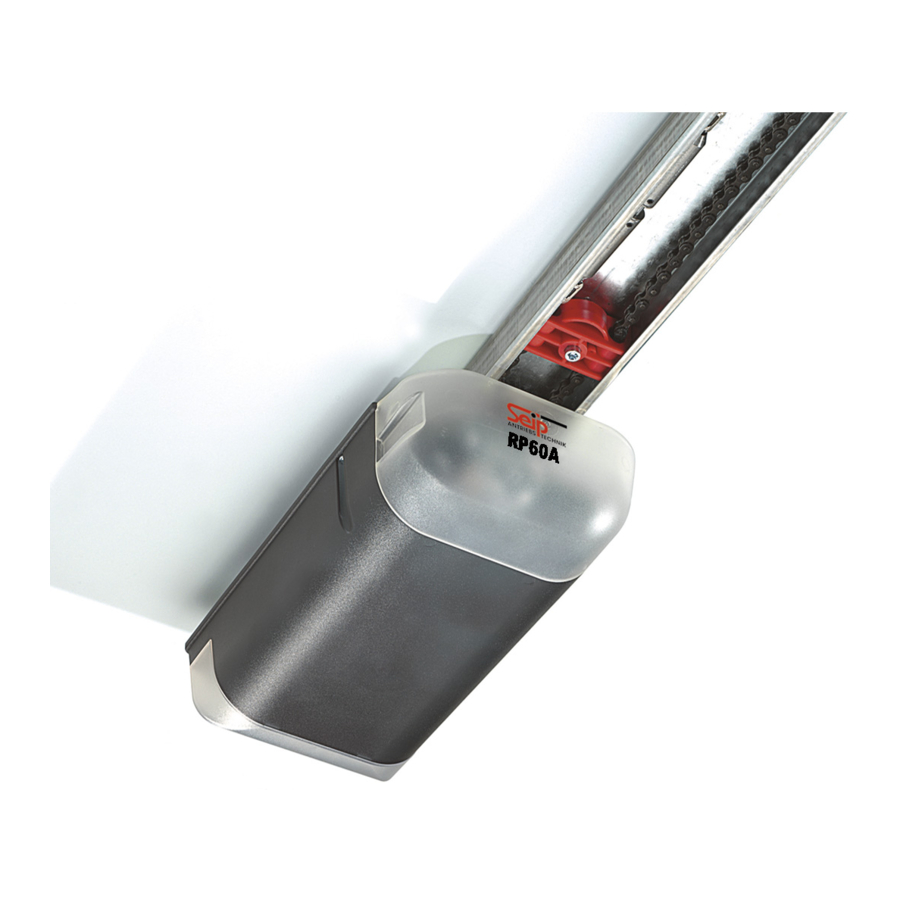
Installation Instructions for the garage door operator RP60A This booklet must be handed over to the end-user together with the user-manual. English 3V1 SKR1W... -
Page 2: Table Of Contents
Content Information and Remarks External Connections 15 Push Button and Key Switch Directives and Regulations Photo-Cell Use of the operators 24V AC Supply Garage Doors Receiver-Module The installers declaration of conformity Older Garage Doors LED-Lamps 16 Important Information for the Installer 3 LED “TEST“... -
Page 3: Information And Remarks
Information and Remarks Important Information for the Installer It is within legal regulation and without restriction, to use a Seip door operator with any garage door that has been ap- proved for use with other certified door operators! Directives and Regulations The garage door operator RP60 complies to the latest European directives and regulations. -
Page 4: Security Advises For The Installation
Information and Remarks Security Advises for the Installation Important Safety Instructions for Installation WARNING: INCORRECT INSTALLATION CAN LEAD TO SEVERE INJURY Follow all Installation Instructions. - Read page 3 of this instruction carefully before the installation - Before installing the drive, remove unnecessary ropes from the existing installation - Maintain the garage door according to the advises on page 3 and to the door manufacturer’s manual... -
Page 5: Installation
Installation Different Conditions for Installation Before installing the operator you should check the garage for the Minimum space above the garage door conditions of installation. You will need optional extras in either of the following situations: 35mm Minimum C-Rail Extension If the garage door is higher than 2.250 mm you will need a c-rail extension. -
Page 6: Pre-Mounting The Operator
Installation Pre-Mounting the operator During this procedure be careful not to twist the chain. Therefore do not lift the parts - slide them along the floor. 1. The operator is laying unpacked in front of you. The motor- head unit is on your right hand side. 2. - Page 7 Installation Installing the operator 3. Attach the C-rail to the front fixing angle (3). Put a carton piece under the motor head unit to avoid damages. 4. To fix the motor head to the ceiling we recommend you to use a ladder (4).
-
Page 8: Adjusting The Running-Length Blocks
Installation Adjusting the running-length blocks These adjustments must be made before the programming of the forces and the running-length. Starting the programming procedure without correctly ad- justed blocks may lead to damages on the garage door and the operator! Vorgehensweise: 1. -
Page 9: The Emergency Release
Installation The Emergency Release In case of a power failure the garage door can be opened by Pic. 1 hand. Therefore the operator first needs to be released. When the garage door is the only entrance It is necessary to connect the emergency release to the door‘s handle (pic. -
Page 10: Printed Circuit Board: Adjustments And Connections
Printed Circuit Board: Adjustments and Connections Devices for Adjustments MO910-V2 HF-MODUL/RECEIVER CARD Pr ge. 24 V This page only shows the functions of the buttons and potentiometers on the P.C.B.. To programme the operator ple- ase refer to page 10 onwards. TEST/RUN-Button (1) Jumper “KRAFT/PRESSURE”... -
Page 11: Programming Running-Length And Force
Printed Circuit Board: Adjustments and Connections Programming Running-Length and Force MO910-V2 HF-MODUL/RECEIVER CARD Pr ge. 24 V Pictures: 1: TEST/RUN-Button 2: LERN/LEARN-Button 3: Jumper for additional force Information Quick Reference To properly use the operator it is necessary to programme the run- 1.) Adjustment of blocks The running-length blocks for ning-length and the force. -
Page 12: Special Functions
Printed Circuit Board: Adjustments and Connections Special Functions Readjusting the time for the internal light Quick Reference „Time for internal light“ The time for the internal light may be adjusted from 10 seconds to 1.) Keep the red LEARN After 3 seconds the operators‘ 5 minutes. -
Page 13: Programming The Soft-Modes
Printed Circuit Board: Adjustments and Connections Special Functions Programming the Soft-Modes The RP60 is shipped with factory pre-set values for the Soft- Modes; if the learning cycle is run without any changes to the TOP soft-mode factory-settings, then the pre-set values will be programmed automatically. -
Page 14: Reducing The Closing Speed
Printed Circuit Board: Adjustments and Connections Enhanced Adjustments Speed Level Reducing the Closing Speed When using the standard programming procedure, then the clo- sing speed is automatically set to maximum; for most CE compliant garage doors no changes are necessary. Why reduce the Closing Speed? Reducing the closing speed will also reduce the forces and the time for reversion which appear when the garage door hits an... -
Page 15: External Connections
- otherwise it may come to unwan- ted stops and reversions during the closing procedure! 24V AC Supply 24V AC power supply for external components (external receiver, photo-cell), a maxi- mum of 200 mAmp. is allowed. Receiver-Module HF-Modul / Plug for Seip remote-receiver cards. Receiver-Card... -
Page 16: Led-Lamps
Printed Circuit Board: Adjustments and Connections LED-Lamps MO910-V2 HF-MODUL/RECEIVER CARD KRAFT/ Pr ge. PRESSURE LERN/LEARN 24 V TEST/RUN Uext 24Vac Function LED “TEST“ (green) Incoming impulse No incoming im- Turns on when: pulse 1.) a device connected to A+B (push-button, key-switch) gives an impulse 2.) the P.C.B.’s TEST-button is pressed 3.) a signal from a registered hand-transmitter is received... -
Page 17: Remote Control
Remote Control Programming the Hand Transmitters Basics Quick reference: programming the first hand transmitter As a standard the operator is equipped with a 433 MHz AM 1.) Keep the LERN/LEARN The operators‘ light will start remote control set. The coding is done via rolling code - the code button pressed for approx. -
Page 18: Additional Information
Remote Control Additional Information 4-Channel MIDI transmitter, 1-Channel Wall Transmitter 433 MHz, rolling code 433 MHz, rolling code Battery Battery Usable types of batteries: A23, 23A, 23L, EL12, VR 22 and Usable types of batteries: A23, 23A, 23L, EL12, VR 22 and MN 21 MN 21 Voltage: 12V... -
Page 19: Technical Information
Technical Information Technical Data RP 60 A Pre-Warning Light adjustable Maximum Pulling Force (adjustable) 60 kg (+/- 4%) Soft-Stop in Closing Direction adjustable Nett Running Length 2.640 mm Force-Setting for Operation automatic Max. Running Length with Extension 4.050 mm Motor 24V DC, low-noise Overall Length Running Speed... -
Page 20: Troubleshooting
Technichal Information Troubleshooting Error Messages The RP 60 is equipped with a system of error messages via the internal lighting and the LED “Diag“. Error messages via the operator‘s light Additional messages only via the LED “Diag“ 2 x blinking 3 x blinking Running-time error - the operator did not reach the running- Photo cell - either an obstacle was recognised by the photo... - Page 21 Forces EN 13241-1 Betriebskräfte Tested for Up-and-Over Doors and Sectionaldoors up to 4m wide and 2,50m high Geprüft für Kipp- und Sektionaltore bis zu 4m Breite und 2,50m Höhe Myke Seip, Walzbachtal-Jöhlingen, 02.05.2009 GmbH ANTRIEBS ANTRIEBS TECHNIK Grombacher Straße 83 75045 Walzbachtal-Jöhlingen...
- Page 22 Schutzanforderungen in Bezug auf die elektromagnetische Verträglichkeit §3(1)2, Artikel 3(1)b)) EN 300 220-1 V2.1.1 EN 300 220-2 V2.1.2 EN 301 489-1 V1.6.1 EN 301 489-3 V1.4.1 EN 60950-1:2006 EMV / EMC Directive 2006/95/EC;2004/108/EC; 99/5/EC Myke Seip, Walzbachtal-Jöhlingen, 09.03.2010 GmbH ANTRIEBS ANTRIEBS TECHNIK Grombacher Straße 83 75045 Walzbachtal-Jöhlingen Germany www.seip.com...
Need help?
Do you have a question about the RP60A and is the answer not in the manual?
Questions and answers