Table of Contents
Advertisement
Advertisement
Table of Contents

Related Manuals for Robe DJ SCAN 150 XT


Summary of Contents for Robe DJ SCAN 150 XT
-
Page 2: Table Of Contents
DJ SCAN 150 XT Table of contents 1. Safety instructions ......................3 2. Operating determinations ..................... 4 3. Description of the device ....................5 4. Installation ........................6 4.1Fitting/Exchanging the lamp ..................6 4.2 Rigging the fixture ..................... 7 4.3 Connection to the mains .................... 8 4.4 DMX-512 connection/connection between fixtures ........... -
Page 3: Safety Instructions
CAUTION! Keep this device away from rain and moisture! Unplug mains lead before opening the housing! FOR YOUR OWN SAFETY, PLEASE READ THIS USER MANUAL CAREFULLY BEFORE YOU INITIAL START - UP! 1. Safety instructions Every person involved with installation and maintenance of this device have to: - be qualilfied - follow the instructions of this manual CAUTION! -
Page 4: Operating Determinations
2. Operating determinations This device was designed for indoor use only. If the device has been exposed to drastic temperature fluctuation (e.g. after transportation), do not switch it on immediately. The arising condensation water might damage your device. Leave the device switched off until it has reached room temperature. -
Page 5: Description Of The Device
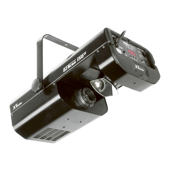
3. Description of the device 1 - Fixation screw for bracket 2 - Bracket 3 - Fastening screws 4 - Objective 5 - Mirror Front panel: 1 - Fuseholder 2 - Powercord 3 - DMX input 4 - DMX output Control board: 1 - Menu-button 2 - Up,Down buttons... -
Page 6: Installation
4. Installation 4.1Fitting/Exchanging the lamp DANGER ! Install the lamps with the device switched off only. Unplug from mains before ! Screw "A" Screw "B" To insert the lamp open the small cover at the rear panel (see the drawing) by loosening the 2 Phillips screws "A" and "B"... -
Page 7: Rigging The Fixture
Lamp adjustment The lampholder is aligned at the factory. Due to differences between lamps, fine adjustment may improve light performance. Strike the lamp and focus the light on a flat surface (wall). Center the hot-spot (the brightest part of the beam) using the 3 adjustment screws "X, Y, Z". -
Page 8: Connection To The Mains
4.3 Connection to the mains The earth has to be connected! Connect the fixture to the mains with the enclosed power-plug. The occupation of the connection-cables is as follows: Cable International Brown Live Light blue Neutral Yellow/Green Earth DANGER TO LIFE! Before taking into operation for the first time, the installation has to be approved by an expert! 4.4 DMX-512 connection/connection between fixtures... -
Page 9: Dmx Protocol
5. DMX PROTOCOL Channel Value Function Type of control 0-255 Control of the pan movement proportional Tilt 0-255 Control of the tilt movement proportional Colours 0 - 7 Open/white step 8 - 15 Turquoise step 16 - 23 step 24 - 31 Cyan step 32 - 39... -
Page 10: Addressing
DJ SCAN 150 XT will respond to the controller. If you set, for example, the address to channel 5, the DJ SCAN 150 XT will use the channel 5 to 8 for control. -
Page 11: Special Functions - Calibration
This function allows you to run a special test program without an external controller, which show you some possibilities of using DJ SCAN 150 XT. Press the [ Menu ] key to run the test program, the "tSt" will start to flash. - Page 12 Colours: - 11 dichroic-filters plus white - UV-filter - 3 dichroic semicolours filters - Colour-wheel with variable rotation speed Static gobos: - 13 static gobos plus open Strobe: - Strobe effect with variable speed (1 - 8 flashes per second) Motor: - 4 high quality stepping-motors controlled by microprocessors Electronics:...
-
Page 13: Maintenance And Cleaning
9. Maintenance and cleaning The operator has to make sure that safety-relating and machine-technical installations are inspected by an expert after every four years in the course of an acceptance test. The operator has to make sure that safety-relating and machine-technical installations are inspected by a skilled person once a year. -
Page 14: Appendix- Changing The Power Supply Settings
10. Appendix- Changing the power supply settings Both the transformer and the ballast must be connected correctly for the local AC voltage and frequency. The wrong settings can cause poor performance or demage of the moving head.The factory settings are printed next to the power cord. - Page 15 US version: 1.Disconnect the fixture from AC power. 2.Remove the front cover by loosening the 4 screws. 3.Move the wire 1 on the transformer connection block to the position according to the desired voltage. 4.Move the wire 2 on the ballast connection block to the position according to the desired frequency (voltage).
Need help?
Do you have a question about the DJ SCAN 150 XT and is the answer not in the manual?
Questions and answers