Table of Contents
Advertisement
Quick Links
Advertisement
Table of Contents

Related Manuals for Ganz ZN-D212XE


Summary of Contents for Ganz ZN-D212XE
- Page 1 IPN2102HD-5511 Installation Guide...
-
Page 2: Information To User
INFORMATION TO USER CAUTION RISK OF ELECTRIC SHOCK, DO NOT OPEN CAUTION: TO REDUCE THE RISK OF ELECTRIC SHOCK, DO NOT REMOVE COVER (OR BACK). CONTACT QUALIFIED SERVICE PERSONNEL FOR INTERNAL PARTS. This symbol is intended to alert the user the presence of un-insulated “dangerous voltage”... -
Page 3: Table Of Contents
ZN-D212XE installation Guide Table of Contents 1. FEATURES ......................... 4 2. PACKAGE CONTENTS ....................5 3. PART NAMES ......................6 4. INSTALLATION ......................7 4.1. Option A. Semi-Flush Mount ................... 7 4.2. Option B. Flush Mount ....................9 4.3. Setting the Image Attribute ..................11 5. -
Page 4: Features
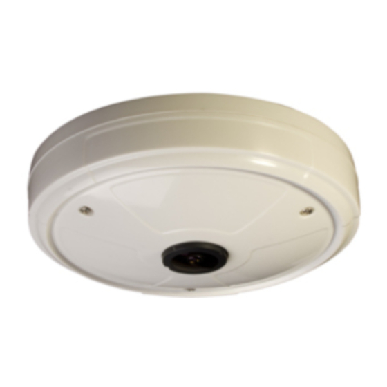
ZN-D212XE installation Guide 1. FEATURES Camera Full HD indoor fisheye IP camera (Vandal proof) High quality compression in real time streaming 1/2.7” 1080p CMOS Image Sensor 180˚ wide and 160˚ vertical angle Remote Zoom/Focus Control(One Click AF) Streaming ... -
Page 5: Package Contents
ZN-D212XE installation Guide 2. PACKAGE CONTENTS Unpack carefully and handle the equipment with care. The packaging contains: Camera DC power adapter Quick installation guide 9-pin and 2-pin terminal blocks FMB mount (for flush mount) Screws and anchors The above contents are subject to change without prior notice. -
Page 6: Part Names
ZN-D212XE installation Guide 3. PART NAMES ① ② *This button is located under PCB. ⑤ ③ ④ ⑥ * Models and their appearance are subject to change without any prior notice. ① Rest button The reset button can be used for restarting the device or resetting it to Factory Default. -
Page 7: Installation
ZN-D212XE installation Guide 4. INSTALLATION 4.1. Option A. Semi-Flush Mount Installation template image’s size scale in this installation guide is not 1:1. The correct-size template design paper can be found inside the package separ ately. Caution 01A.01... - Page 8 ZN-D212XE installation Guide Place the installation template on a surface where camera is going to be installed and mark the anchor block placements. 2) Drill and insert anchor blocks on a marked surface. 3) Mount the main camera body by aligning the anchor blocks and hold against the mounting surface..
-
Page 9: Option B. Flush Mount
ZN-D212XE installation Guide 4.2. Option B. Flush Mount Installation template (FMB) 21 V1.0 Installation template image’s size scale in this installation guide is not 1:1. The correct-size template design paper can be found inside the package separ ately. Caution 01A.01... - Page 10 ZN-D212XE installation Guide Trace the size on a surface where the device will be inserted with the provided template and create a hole. Also, mark on a surface where anchor blocks will be inserted. 2) Drill and insert anchor blocks on a marked surface.
-
Page 11: Setting The Image Attribute
ZN-D212XE installation Guide 4.3. Setting the Image Attribute Through the camera’s webpage, users can configure image settings. The camera image’s brightness, contrast, saturation and sharpness are adjustable through the image settings. (Setup > Video & Audio > Camera). 01A.01... -
Page 12: Connections
ZN-D212XE installation Guide N / A N / A 5. CONNECTIONS N / A N / A VIDEO AUDIO DC12V ETHERNET MICRO SD ⑥ N / A N / A ① Audio input/output The camera has a mono audio input and a mono audio output. Due to low audio output power,... - Page 13 ZN-D212XE installation Guide Internal +3.3V Internal Output of Output of Sensor Sensor Relay Type Voltage Type ③ Alarm (DO) connection Only the relay type is supported. Relay Rating: Max 24VDC 50mA Do not exceed the maximum relay rating. Caution Internal...
- Page 14 ZN-D212XE installation Guide ⑤ LAN connection This is a RJ45 LAN connector for 10/100 Base-T Ethernet. Connect a LAN cable. Green LED Orange LED When the device is connected, the orange LED stays on while green LED continues to blink.
-
Page 15: Configuration
ZN-D212XE installation Guide 6. CONFIGURATION 6.1.Set up network environment The default IP address of the device is 192.168.XXX.XXX. Users can identify the IP address of the device from converting the MAC address’s hexadecimal numbers, which is attached to the device. Be sure that the device and PC are on a same area network before running the installation. -
Page 16: Custom Ip Environment
ZN-D212XE installation Guide 6.1.2. Custom IP Environment IPAdminTool is provided with SDK at the following SDK path. {SDK root}\BIN\TOOLS\AdminTool\ IPAdminTool is a management tool, which automatically scans all of the network products for users to perform administrative tasks, which includes network configurations, firmware update, device reboot, and device organizations. -
Page 17: View Video On Web Page
ZN-D212XE installation Guide 6.2. View video on web page Type the proper IP address to view the live streaming images through a web browser. The default username and password is root / pass. The browser asks to install the ActiveX. Click Allow. -
Page 18: View Video Using Ipadmin Tool
ZN-D212XE installation Guide Follow the instructions of the dialog boxes and complete the installation. Once the installation is complete, start the web browser again and check if video stream is displayed in the main view frame. If “This software requires the Microsoft XML Parser V6 or higher. Please download MSXML6 from the Microsoft website to continue. -
Page 19: Reset
ZN-D212XE installation Guide 6.3. Reset Perform the following procedures to reset your device: Push the Reset button and hold for 1~2 seconds. Wait for the system to reboot. 6.4. Factory Default If you reset your device to the factory default setting, all parameters including the IP address will be initialized. -
Page 20: Appendix (A): Specifications
ZN-D212XE installation Guide APPENDIX (A): SPECIFICATIONS Summary Camera Module Image Sensor 1/2.7” 1080p CMOS CMOS Effective Pixels 1920x1080 Scanning system Progressive scanning Resolution 1920 x 1080 Min. Color: 1.0 lux, F1.2 ELECTRICAL Illumination BW: 0.001 Lux (B/W, Sens-up 32X) AGC Control... -
Page 21: Electrical Characteristics
ZN-D212XE installation Guide Electrical Characteristics Power Source DC 12V / PoE IEEE802.3af (Class 0) Power Consumption Max 500mA Video Output 1 Vp-p, 75Ω, Composite Audio Input Linein, 1.43Vp-p(Min 1.35Vp-p, max 1.49 Vp-p), 39 KΩ Audio Output Lineout, 46mW Power, 16 Ω... -
Page 22: Appendix (B): Power Over Ethernet
ZN-D212XE installation Guide APPENDIX (B): POWER OVER ETHERNET The Power over Ethernet (PoE) is designed to extract power from a conventional twisted pair Category 5 Ethernet cable, conforming to the IEEE 802.3af Power-over-Ethernet (PoE) standard. IEEE 802.3af allows for two power options for Category 5 cables. -
Page 23: Appendix (C): Dimensions
ZN-D212XE installation Guide APPENDIX (C): DIMENSIONS (Unit: mm) 01A.01... - Page 24 ZN-D212XE installation Guide (Unit: mm) 01A.01...
-
Page 25: Appendix (D): Hexadecimal-Decimal Conversion Table
ZN-D212XE installation Guide APPENDIX (D): HEXADECIMAL-DECIMAL CONVERSION TABLE Refer to the following table when you convert the MAC address of your device to IP address. 01A.01... -
Page 26: Revision History
ZN-D212XE installation Guide REVISION HISTORY MAN# DATE(M/D/Y) Comments 01A.01 05/21/2012 First release version 01A.01...
Need help?
Do you have a question about the ZN-D212XE and is the answer not in the manual?
Questions and answers