Table of Contents
Advertisement
Quick Links
Advertisement
Table of Contents

Subscribe to Our Youtube Channel
Related Manuals for CTC Union VDTU2-B110


Summary of Contents for CTC Union VDTU2-B110
- Page 1 VDTU2-B110 VDSL2 LAN Extender...
- Page 2 User Manual Version 2.00 March 2013 This document is the current official release manual. Please check CTC Union's website for any updated manual or contact us by E-mail at sales@ctcu.com. Please address any comments for improving this manual or to point out omissions or errors to marketing@ctcu.com. Thank you.
-
Page 3: Table Of Contents
Table of Contents Chapter 1 Introduction ..........................4 1.1 Features ................................ 4 1.2 Specification ..............................5 1.3 Applications ..............................6 Chapter 2 Hardware Installation ........................ 7 2.1 Front Panel ..............................7 2.2 Rear Panel ..............................10 2.3 Installation ..............................11 Appendix I .............................. -
Page 4: Chapter 1 Introduction
Chapter 1 Introduction 100M VDSL2 Ethernet Extender is a high-speed Ethernet Extender with one Ethernet port (RJ-45 connector) and one VDSL port (RJ-45 connector). It is a bridge mode modem, well accommodating VDSL2 (Very-high-data-rate Digital Subscriber Loop) technology to extend Ethernet service over single-pair phone line. It is compliant to ITU-T G.993.2 standard and supports VDSL2 30a profile that features 100Mbps of symmetric data rate over the existing copper wires. -
Page 5: Specification
1.2 Specification 4-position DIP Switch LAN Interface: Selectable CO or CPE mode RJ-45 connector Selectable 30a or 17a (VDSL2 Profile) Complying with IEEE Selectable Band plan (Symmetric or Asymmetric) 802.3/802.3u/802.3x Selectable target SNR margin (6dB or 9dB) ... -
Page 6: Applications
1.3 Applications LAN Extender Application... -
Page 7: Chapter 2 Hardware Installation
Chapter 2 Hardware Installation This chapter shows the front panel and how to install the hardware. 2.1 Front Panel Front panel can be separated into five parts from left to right: DIP switch RJ-45 connector for Ethernet LEDs for Ethernet LEDs for VDSL RJ-45 connector for VDSL... - Page 8 The RJ-45 is designed to connect to the Local Network with the Unshielded Twisted Pair (UTP) cable. The LEDs on top of RJ-45 connector show the status below: blinking On Off LEDs for LAN Activity Link UP Link UP 100Mbps 10Mbps...
- Page 9 The following table describes the DIP Switches’ setting. Pin 1 Pin 2 Pin 3 Pin 4 Side Channel Rate Limit Symmetric Asymmetric Pin 1: OT, RT switch OT: LAN Extender acts as Central Office (CO) side. RT: LAN Extender acts as Customer Premise Equipment (CPE) side. Pin 2: Impulse noise protection 30a: High Speed Mode.
-
Page 10: Rear Panel
The following table describes the LEDs’ function of the product. blinking On Off LEDs for VDSL Device Power ON Device Power OFF CPE-mode CO-mode Slow: Idle Linked Off line Fast: Training 2.2 Rear Panel The DC Jack on the rear panel can be connected to power supply adaptor with the DC input. -
Page 11: Installation
2.3 Installation Please see the illustration below... -
Page 12: Appendix I
Appendix I Connector Architecture Ethernet Port Connector (RJ-45) The Ethernet Port interface is an 8 position Modular Jack. The table below displays the pin out assignments. Pin Number Assignment (MDI-X) Figure RX+; Receive data + RX-; Receive data - TX+; Transmit data + Not used Not used TX-;... - Page 13 VDSL Interface Pin Assignments (RJ-45) The VDSL interface is standard eight-pin modular jack. The table below displays the pin out assignments. Pin Number Description Figure Not used Not used Not used ANALOG Input/Output ANALOG Input/Output Front View Not used Not used View Not used...
-
Page 14: Appendix Ii
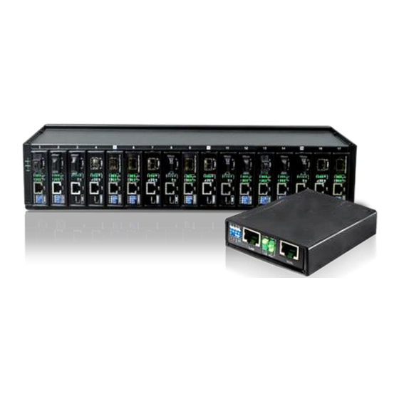
VDSL LAN Extender User Manual V200 Appendix II Chassis Accessory There is also the Chassis solution for application on the rack in CO side. The major feature of the Chassis is listed below: • 2U, 19”, 17-Slot rack • Support 17-slot in one unit •...
Need help?
Do you have a question about the VDTU2-B110 and is the answer not in the manual?
Questions and answers