
Subscribe to Our Youtube Channel
Related Manuals for ELRO DWH series


Summary of Contents for ELRO DWH series
- Page 1 DWH SERIES VIDEO SECURITY SYSTEM Installation and Operation Instruction Manual This manual should be retained in a safe place for future reference...
-
Page 2: Table Of Contents
CONTENTS IMPORTANT NOTES READ BEFORE START REQUIREMENT FOR REMOTE VIEW PLANNING YOUR LAYOUT SAFETY INSTALLATION TIPS KIT CONTENTS QUICK START GUIDE SETUP THE CAMERA SETUP THE TOUCH CREEN MONITOR / RECEIVER SYETEM OPERATION REMOTE ACCESS GETTING TO KNOW THE RECEIVER AND CAMERA INSTALLATION SETTING THE CAMERA CHANNEL PAIRING THE CAMERA TO RECEIVER... -
Page 3: Important Notes
CONTENTS SYSTEM REQUIREMENT ALARM SETUP SCREEN PLANNING YOUR LAYOUT PERIOD SAFETY INSTALLATION TIPS MELODY IMPORTANT NOTES TO READ BEFORE START SYSTEM SETUP SCREEN KIT CONTENTS POWER SAVING QUICK START GUIDE SCREEN AUTO LOCK SETUP THE CAMERA TIME SETUP THE TOUCH CREEN MONITOR / RECEIVER CLOCK ALARM TIME SETTING SYETEM OPERATION... -
Page 4: System Requirement Alarm Setup Screen
IMPORTANT NOTICE Please Read Before You Start... - Page 5 FCC/CE WARNING This equipment has been tested and found to comply with limits for a Class B digital device, pursuant to Part 15 of the FCC rules and ETSI (EN) 300 328. These limits are designed to provide reasonable protection against harmful interference in residential installations. This equipment generates, uses, and can radiate radio frequency energy, and if not installed and used in accordance with the instructions, may cause harmful interference to radio communications.
-
Page 6: Read Before Start
System “Device ID” and “Password” are provided on a label applied at the back of the LCD Monitor (behind the pull out stand). The “Device ID” and “Password” are needed for remote viewing. For security purpose, it is recommenced for user to copy the “Device ID”... -
Page 7: Planning Your Layout
PLANNING YOUR LAYOUT SAFETY AND INSTALLATION TIPS LCD Touch Screen Monitor keep away from heat sources and high temperature places Avoid direct sunlight Avoid humid places Avoid vibration Install in a ventilated environment The supplied SD card can be replaced with up to a 32GB SD card if required Installation Notes Always follow manufacturers advice when using power tools, steps,... -
Page 8: Kit Contents Power Saving
any holes through an external wall for a cable, ensure the hole is sealed up using a suitable sealant to prevent drafts. To prevent a fire or electrical shock hazard, do not attempt to open the housing while the camera is exposed to rain water or wet conditions. Do not expose any wiring connections to weathering. -
Page 9: Kit Contents
KIT CONTENTS 1 x Camera 1 x Touch Screen LCD Monitor w/Cradle 2 x 5V/1A Power Adaptor 1 x Camera Stand 1 x Antenna 1 x Internet Cable 1 x Fixings Pack 1 x Instruction Manual... -
Page 10: Quick Start Guide
QUICK START GUIDE For further details on the installation of the camera bracket and fixings please refer to page12. Set Up the Camera Set Up the Touch Screen Monitor 1. Flip out the stand, extend the antenna, connect AC/DC adapter to the input on the side of the monitor. -
Page 11: Syetem Operation
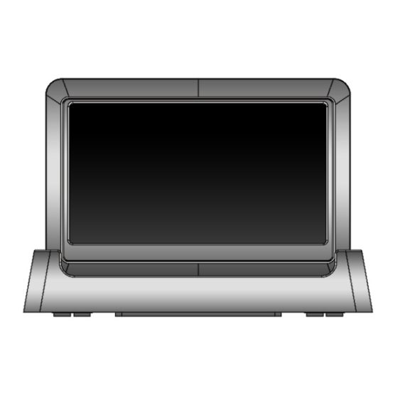
The 7" touch screen monitor is fitted with a rechargeable battery and can operate for up to 4 hours on battery power once fully charged. The monitor can be carried around anywhere within operating range of the cameras, but should be used in a dry environment as it is not weatherproof. -
Page 12: Getting To Know The Receiver And Camera
GETTING TO KNOW THE MONITOR AND CAMERA Cradle Antenna Receiver (back/side) Reset Receiver Power Power Dock Data Cable Connection SD slot AC Power Connection Pull-Out AC Power Stand Connection Camera Front view Back view Antenna connector Power status Power pigtail Link status Power/Pair button... -
Page 13: Installation
INSTALLATION Setting the Camera Channel (Optional) The wireless cameras will be supplied preset to channel 1. The wireless monitor supports up to 4 wireless cameras. Follow the step below to setup or change the monitor channel of the camera. If you are adding another camera to link with the supplied monitor in this kit, then ensure its channel is set to a different channel to the existing camera(s). -
Page 14: Camera Installation
CAMERA INSTALLATION: A. Secure camera stand on the wall B. Loosen the thumb screw C. Adjust the camera to the correct viewing position then tighten the screw and T-bolt. Outdoor installation of the camera: If connecting the wiring connections externally: Use masonry drill bit to pass the camera’s power supply connection through the external wall (to outside). -
Page 15: System Introduction
SYSTEM INTRODUCTION Your monitor’s system software operates through a series of screens that let you choose groups of operations. For example, when you tap on the camera icon in the Pop-up menus, you can set how you want the main viewing screen, “the Live screen”... - Page 16 WHAT THE ICONS MEAN Icon What it does Select how you want the Live screen to display camera input: Camera Scan between cameras (5 seconds) Mode Quad view (all paired cameras display) Full view (1 camera displays on full screen) Volume Adjust the volume level.
-
Page 17: Zoom Feature
Live Screen Displays The Live screen displays in 2 views - Quad View or Full View. Quad View displays the images in 4 quadrants (only display camera that is ON). Tap a quadrant to display single camera view / full view. Tap on that image again to return to Quad View. -
Page 18: Playing Back Recorded Video
Playing Back Recorded Video 1. Tap on the highlighted day containing the recording you want to view. The Record List screen will display that day’s recordings listed in a folder. If you tap on a day that is not highlighted, a folder displays with no recordings listed. -
Page 19: System Operation Trouble Shooting
Main Screen Sub Screens What it Does Camera Setup Pairs new cameras to the receiver. Camera Setup Camera on Makes the cameras visible to the monitor. Brightness Brightens or darkens the video of that camera. Motion Detection Records when something moves in front of the camera. -
Page 20: System Operation
SYSTEM OPERATION Camera Setup Screen Tap on camera setup. This screen should display: Camera Pairing Your camera is paired to the monitor at the factory to channel 1. To add new camera(s) to your system, you have to pair it to the different channel(s). -
Page 21: Brightness
Brightness Tap the camera to change brightness level. The default brightness is 0, and the range is from -2 through 2. Recorder Setup Screen Motion Detection Tap the camera’s to set the sensitivity to Off, Low or High. Default = low. The screen will return to the Motion Detection screen after 10 seconds or when you press the Back icon. -
Page 22: Schedule Record
Schedule Record Up to 5 scheduled recording sessions available in a single day. You are limited to the size of the SD card for how long a total recording time you have. These recording sessions must begin and end within a single 24- hour period. -
Page 23: Clear A Schedule Record
Clear a Scheduled Recording 1. Access the Schedule Record screen. 2. Tap on the scheduled recording you want to clear (1-5). The screen displays the settings for that schedule. 3. Tap CLEAR. The screen resets to the default values for that recording slot. Network Setup Screen The Network Setup screen allows you to select your internet type, set a security code. -
Page 24: Security Code Setup
3. Tap OK at the system reboot prompt. The Network Setup screen displays. Security Code Set up your security code to limit who can have access to the system from a remote location. 1. Tap Security Code icon to display the Security Code screen. 2. -
Page 25: Network Information
4. Enter your security code. 5. Tap OK. The system will return to Network Setup screen. Note: Security code must be entered to gain remote access. Network Information 1. Tap the Network Information icon to display the Network Information screen. 2. - Page 26 Period This selection allows you to select the alarm/siren duration when Motion Detection is turned on and motion is detected. 1. Tap Period. The Set Siren Duration screen displays. 2. Select the alarm duration time required 3. Tap the BACK arrow to return to the previous screen. Melody This selection allows you to select a melody for the siren.
- Page 27 System Setup Screen Power Saving In Power Saving mode, the monitor will shut off LCD after idle for 2 minutes. Press Power button once to reactive the monitor. If a motion detection event or scheduled recording begins, the LCD turns back on automatically. 1.
- Page 28 Screen Auto Lock In Auto Lock mode, the monitor will enter screen lock mode after it has been idle for 2 minutes. Auto Lock disables the touch screen and removed the icons from the display. 1. Tap Screen Auto Lock 2.
- Page 29 Clock Alarm This feature operates as an independent alarm clock. It does not affect the operation of live video or recording video. 1. Tap to display the Clock Alarm screen. 2. Tap on an alarm button (total of 5 to select from). 3.
-
Page 30: Getting To Know The Receiver And Camera System Upgrade
3. Tap on the AM/PM block to switch between the two. 4. Tap SAVE when you are finished. Timer This feature operates as an independent alarm clock. It does not affect the operation of live video of recoding video. 1. Tap to display the Time Setting screen. - Page 31 System Upgrade To upgrade the firmware from the vendor website, you must download and store it in the SD card root directory. Refer to Upgrading Your System Software (p.48) Language English is the default language. If you change the languages, all system settings default to the original factory settings.
- Page 32 Quick Tips The Quick Tips screen provides additional details on important subjects of system operation. Tap on a subject to display the information. REMOTE ACCESS Overview This Smartphone Wireless CCTV Series lets you view live video from your iPhone, iPad, or Android smartphone or tablet. Free apps are available through the iTunes App Store or the Android Market.
-
Page 33: Connecting To The Internet
Connecting to the internet The docking cradle charges your monitor as well as provides an internet connection. When you are connected to the internet, monitor's touch operation will become limited. Monitor's touch operation will resume normal after disconnecting from the internet by select Charge Only option from the pop up menu, or remove monitor from its docking cradle. -
Page 34: Maintaining Your System
3. The screen will display the following: 4. Tap Connect to internet? The Live screen is now locked and you can view live video through your portal account and mobile devices. 5. Once internet connectivity is set, the system will memorize the setting. The next time you place the monitor back into the cradle, the system will automatically connect to internet. -
Page 35: Trouble Shooting
TROUBLE SHOOTING TROUBLE SOLUTIONS The receiver and cameras Screen lock may be on. Tap the Power are on but there is no button to unlock the screen. image on the screen No image Make sure the camera is power on. Make sure the monitor has enough charge / connect it to AC/DC adaptor. - Page 36 improve the night vision or place it in a well lit area (recommend to install a security lamp to improve lighting). LIVE screen has no icons. Screen lock may be on. Tap the Power button to unlock the screen. System locked up Power off the receiver and restart.
-
Page 37: Product Specification
PRODUCT SPECIFICATION Camera Receiver Maximum channels 150 metres in open space Communication Range 800 x 480 LCD Monitor Resolution Single Camera: 480x272 / Multiple Camera: 320x240 Camera Resolution Operating Temperature C ~ 50 DC 5V / 1A Operating Voltage Current Consumption 500mA (MAX) 800mA (MAX) Night Vision...
Need help?
Do you have a question about the DWH series and is the answer not in the manual?
Questions and answers