Table of Contents
Advertisement
Quick Links
Instruction Manual book
ITEM CODE:BH 141
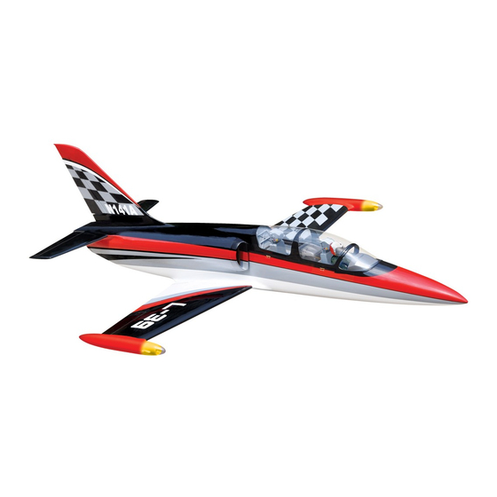
SPECIFICATION
Wingspan:
1,450mm
57.09 in.
Length :
1,860 mm
73.23 in.
Weight :
4.3-4.6 kg
9.46-10.12 Lbs.
Radio :
08 channels.
Servo : 08 mini servos +3 servos retracts(FUTABA,S3170G).
EDF:90MM MIDI - FAN EVO/HET 650-68 -2000
Battery: 6S-LIPO-22.2V-5,500-7,200mAh
Speed control: 120A
Made in Vietnam.
Advertisement
Table of Contents

Related Manuals for Black Horce Model L-39 Albatros BH 141


Summary of Contents for Black Horce Model L-39 Albatros BH 141
- Page 1 Instruction Manual book ITEM CODE:BH 141 SPECIFICATION Wingspan: 1,450mm 57.09 in. Length : 1,860 mm 73.23 in. Weight : 4.3-4.6 kg 9.46-10.12 Lbs. Radio : 08 channels.
-
Page 2: Instruction Manual
L-39 ALBATROS Instruction Manual Item code: BH141 This instruction manual is designed to help you build a great flying aeroplane. Please read this L-39 ALBATROS. manual thoroughly before starting assembly of your Use the parts listing below to identify all parts. WARNING. -
Page 3: Safety Precaution
L-39 ALBATROS Instruction Manual Item code: BH141 Caution: this model is not a toy! If you are a beginner to this type of powered model, please ask an experienced model flyer for help and support. If you attempt to operate the model without knowing what you are doing you could easily injure yourself or somebody else. - Page 4 L-39 ALBATROS Instruction Manual Item code: BH141 REPLACEMENT LARGE PARTS A .Fuselage. B. Wing panel (B1,B2). C. Horizontal stabilizer(D1,D2). D. Vertical stabilizer. E. Carbon tube wing dihedral brace. G. Decal sheet. K.Pilot F. Carbon tube Horizontal stabilizer. REPLACEMENT SMALL PARTS 6.wire cable(nose gear) 3.Plastic parts of 4.
-
Page 5: Installing The Aileron Servos
L-39 ALBATROS Instruction Manual Item code: BH141 Remove covering I. AILERON. Servo tray. 1.INSTALLING THE AILERON SERVOS. 1) Install the rubber grommets and brass eyelets onto the aileron servos. Top side Secure. 3) Using the thread as a guide and using masking tape, tape the servo lead to the end of the thread: carefully pull the thread out. -
Page 6: Installing The Aileron Linkages
L-39 ALBATROS Instruction Manual Item code: BH141 INSTALLING THE AILERON 5. Instal servo tray with aileron servo into the wing as same as picture below. LINKAGES. Installing the aileron linkages as pictures below. 2x10mm. 60 mm. Secure. Repeat the procedure for the other wing half. - Page 7 L-39 ALBATROS Instruction Manual Item code: BH141 II. FLAP Secure 1.INSTALLING THE FLAP SERVO Flap. servo tray. Electric wire. Repeat the procedure for the other wing half. Electric wire. 2.INSTALLING THE FLAP CONTROL HORN. Install flap control horn as same as thread picture below.
- Page 8 L-39 ALBATROS Instruction Manual Item code: BH141 Bottom side. Aileron. A+B Epoxy Flap. PLUS glue Repeat the procedure for the other wing half. INSTALLING RETRACT SERVOS. See pictures below: Control horn Retract of the flap. servos 3.INSTALLING THE FLAP Top side LINKAGES.
- Page 9 L-39 ALBATROS Instruction Manual Item code: BH141 Retract servos INSTALLING RETRACTABLE LANDING GEAR. PARTS REQUIRED 3x15mm 5x30mm connector. Bottom side. Top side...
- Page 10 L-39 ALBATROS Instruction Manual Item code: BH141 3x15mm. Secure. INSTALLING THE RETRACT PUSHROD. See pictures below: 5x30mm Secure. Secure.
- Page 11 L-39 ALBATROS Instruction Manual Item code: BH141 INSTALLING ELECTRIC EDF-90MM. (Not included) See pictures below: Cut. retract pushrod Bottom side Open 2x10mm. Secure Bottom side Repeat the procedure for the other gear.
- Page 12 L-39 ALBATROS Instruction Manual Item code: BH141 .Plastic parts of tail fuselage. 3x 12mm Secure. A+B Epoxy PLUS glue. Left side...
-
Page 13: Elevator Control Horn Installation
L-39 ALBATROS Instruction Manual Item code: BH141 HORIZONTAL STABILIZER. ELEVATOR SERVO INSTALLATION. 1. Install the rubber grommets and brass collets into the elevator servo. Test fit the servo into the servo tray. 2. Mount the servo to the tray using the mounting screws provided with your radio system. -
Page 14: Elevator Pushrod Installation
L-39 ALBATROS Instruction Manual Item code: BH141 Left side. Bottom side A+B Epoxy PLUS glue. Right side. Right side HORIZONTAL STABILIZER. Horizontal stabilizer installation See picture below. Elevator control horn ELEVATOR PUSHROD INSTALLATION. Elevator pushrod install as same as the way of aileron pushrod. -
Page 15: Vertical Installation
L-39 ALBATROS Instruction Manual Item code: BH141 Epoxy glue. Right side. Left side. C/A glue. Epoxy glue. Top side. Bottom side. C/A glue. Elevator pushrod Elevator pushrod VERTICAL INSTALLATION See picture below: Left side... -
Page 16: Rudder Control Horn Installa- Tion
L-39 ALBATROS Instruction Manual Item code: BH141 Secure. Rudder servo install as same as method of elevator servo. RUDDER CONTROL HORN INSTALLA- See picture below: TION. Rudder control horn install as same as the way of aileron control horn. Please see pic- tures below. -
Page 17: Rudder Pushrod Installation
L-39 ALBATROS Instruction Manual Item code: BH141 RUDDER PUSHROD INSTALLATION. Rudder pushrod install as same as the way of aileron pushrod. 60mm. Epoxy glue... - Page 18 L-39 ALBATROS Instruction Manual Item code: BH141 Top side INSTALLING RETRACT SERVO NOSE GEAR. S e c u r e See picture below: 3x15mm. Retract servo nose gear 5x30mm Retract servo nose gear INSTALLING RETRACT NOSE GEAR. See picture below: 3x15mm...
- Page 19 L-39 ALBATROS Instruction Manual Item code: BH141 wire cable. Secure. wire cable. INSTALLING SERVO NOSE GEAR. See picture below: Servo nose gear Open. Secure Retract pushrod (nose gear) wire cable.
- Page 20 L-39 ALBATROS Instruction Manual Item code: BH141 INSTALLING THE ESC-RECEIVER AND BATTERY. 1. Plug the servo leads and the switch lead into the receiver. You may want to plug an aileron extension into the receiver to make plugging in the aileron servo lead easier Servo when you are installing the wing .
-
Page 21: Installing Cockpit Fuselage
L-39 ALBATROS Instruction Manual Item code: BH141 Battery Receiver. A+B Epoxy PLus glue Receiver. INSTALLING COCKPIT FUSELAGE . See picture below: Pilot Top side WING ATTACHMENT. 1.Locate the carbon tube wing dihedral brace. 12 mm 510mm. - Page 22 L-39 ALBATROS Instruction Manual Item code: BH141 Right wing. 2. Attach the carbon tube into the fuselage. 3.Insert two wing panels as pictures below. Bottom side Bottom side Left wing. Secure. Secure.
- Page 23 L-39 ALBATROS Instruction Manual Item code: BH141 Lift the model. If the tail drops when you lift, the model is “tail heavy” and you must add Bottom side. weigh* to the nose. If the nose drops, it is “nose heavy” and you must add weight* to the tail to balance.
-
Page 24: Control Throws
L-39 ALBATROS Instruction Manual Item code: BH141 CONTROL THROWS. PRE-FLIGHT CHECK. 1) We highly recommend setting up a 1) Completely charge your transmitter and plane using the control throws listed. receiver batteries before your first day of fly- ing.
Need help?
Do you have a question about the L-39 Albatros BH 141 and is the answer not in the manual?
Questions and answers