Table of Contents
Advertisement
Quick Links
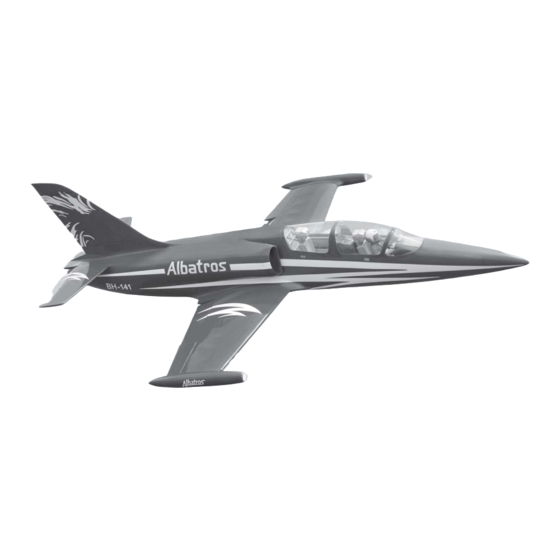
SPECIFICATION
Wingspan:
Length :
Weight :
Parts listing required (not included).
Radio :
Servo :
EDF: DS51- AXI - HDS 90mm 10 Blade Impeller
Motor : HET 700 -68 - 1200KV
Battery:2 Packs x 5 Cells LIPO 37V-5,000mAH 50c.
(Or) EDF: 90MM MIDI - FAN EVO/HET 650-68 -1.500KV
Battery: 8S-LIPO-29,6V-6,000mAh.
Speed control: 120A
Instruction Manual book
1,450mm
1,860 mm
4.6-4.9 kg
08 channels.
08
size (29 x 13 x 30) mm.
57.09 in.
73.23 in.
10.12-10.78 Lbs.
ITEM CODE:BH 141
Made in Vietnam.
Advertisement
Table of Contents

Related Manuals for Black Horce Model L-39 Albatros BH141


Summary of Contents for Black Horce Model L-39 Albatros BH141
- Page 1 Instruction Manual book ITEM CODE:BH 141 SPECIFICATION Wingspan: 1,450mm 57.09 in. Length : 1,860 mm 73.23 in. Weight : 4.6-4.9 kg 10.12-10.78 Lbs. Parts listing required (not included). ...
-
Page 2: Instruction Manual
L-39 ALBATROS Instruction Manual Item code: BH141 This instruction manual is designed to help you build a great flying aeroplane. Please read this L-39 ALBATROS. manual thoroughly before starting assembly of your Use the parts listing below to identify all parts. WARNING. -
Page 3: Safety Precaution
L-39 ALBATROS Instruction Manual Item code: BH141 Caution: this model is not a toy! If you are a beginner to this type of powered model, please ask an experienced model flyer for help and support. If you attempt to operate the model without knowing what you are doing you could easily injure yourself or somebody else. - Page 4 L-39 ALBATROS Instruction Manual Item code: BH141 REPLACEMENT LARGE PARTS A .Fuselage. B. Wing panel (B1,B2). C. Horizontal stabilizer(D1,D2). D. Vertical stabilizer. E. Aluminium tube wing dihedral brace. G. Decal sheet. K.Pilot F. Aluminium tube Horizontal stabilizer. REPLACEMENT SMALL PARTS 3.Plastic parts of tail fuselage.
-
Page 5: Installing The Aileron Servos
L-39 ALBATROS Instruction Manual Item code: BH141 Servo tray. I. AILERON. 1.INSTALLING THE AILERON SERVOS. Servo tray. 1) Install the rubber grommets and brass eyelets onto the aileron servos. Bottom side. Secure. Aileron Flap 2) Using a modeling knife, remove the cov- ... -
Page 6: Installing The Aileron Linkages
L-39 ALBATROS Instruction Manual Item code: BH141 INSTALLING THE AILERON 5. Instal servo tray with aileron servo into the wing as same as picture below. LINKAGES. Installing the aileron linkages as pictures below. 2x10mm. 60 mm. Secure. Repeat the procedure for the other wing half. - Page 7 L-39 ALBATROS Instruction Manual Item code: BH141 II. FLAP Secure 1.INSTALLING THE FLAP SERVO Flap. servo tray. Electric wire. Repeat the procedure for the other wing half. Electric wire. 2.INSTALLING THE FLAP CONTROL HORN. Install flap control horn as same as thread picture below.
- Page 8 L-39 ALBATROS Instruction Manual Item code: BH141 Bottom side. A+B Epoxy Aileron. PLUS glue Flap. Repeat the procedure for the other wing half. INSTALLING ELECTRIC GEAR RETRACTS. PARTS REQUIRED Control horn of the flap. 3.INSTALLING THE FLAP LINKAGES. Installing the flap linkages as pictures below.
- Page 9 L-39 ALBATROS Instruction Manual Item code: BH141 4x12mm Secure. 3x15mm Bottom side Secure. Repeat the procedure for the other gear. INSTALLING ELECTRIC EDF-90MM. (Not included) See pictures below:...
- Page 10 L-39 ALBATROS Instruction Manual Item code: BH141 Bottom side Secure. Open .Plastic parts of tail fuselage. 3x 12mm...
- Page 11 L-39 ALBATROS Instruction Manual Item code: BH141 Horizontal stabilizer installation . See picture below. Bottom side A+B Epoxy PLUS glue. Left side HORIZONTAL STABILIZER. ELEVATOR SERVO INSTALLATION. 1. Install the rubber grommets and brass 2x10mm. collets into the elevator servo. Test fit the servo into the servo tray.
-
Page 12: Elevator Control Horn Installation
L-39 ALBATROS Instruction Manual Item code: BH141 Left horizontal stabilizer Secure. ELEVATOR CONTROL HORN INSTALLATION. Elevator control horn install as same as the way of aileron control horn. Please see pic- tures below. Control horn of elevator. E l e v a t o r pushrod Left side. - Page 13 L-39 ALBATROS Instruction Manual Item code: BH141 Left side Epoxy glue. Right side. C/A glue. Left side. Top side. Epoxy glue. Bottom side. Elevator pushrod Elevator pushrod C/A glue.
-
Page 14: Vertical Installation
L-39 ALBATROS Instruction Manual Item code: BH141 VERTICAL INSTALLATION See picture below: 2x10mm. Secure. RUDDER CONTROL HORN INSTALLA- TION. Rudder control horn install as same as the way of aileron control horn. Please see pic- tures below. Control horn of Rudder. Rudder servo install as same as method of elevator servo. -
Page 15: Rudder Pushrod Installation
L-39 ALBATROS Instruction Manual Item code: BH141 RUDDER PUSHROD INSTALLATION. Rudder pushrod install as same as the way of aileron pushrod. 60mm. Epoxy glue... - Page 16 L-39 ALBATROS Instruction Manual Item code: BH141 Top side S e c u r e 3x10mm. INSTALLING ELECTRIC NOSE GEAR RETRACT. See picture below: ( Electric Not Included.) Only Including Oleo Strut Nose Gear. 3x15mm 2x8mm 3x10mm S e c u r e 2x8mm.
- Page 17 L-39 ALBATROS Instruction Manual Item code: BH141 wire cable. INSTALLING SERVO NOSE GEAR. See picture below: Servo nose gear wire cable. Open. wire cable. 3x15mm Secure...
- Page 18 L-39 ALBATROS Instruction Manual Item code: BH141 2. Wrap the receiver and battery pack in the protective foam to protect them from vi- bration. Use a rubber band or masking tape to hold the foam in place. Servo ...
-
Page 19: Installing Cockpit Fuselage
L-39 ALBATROS Instruction Manual Item code: BH141 Receiver. INSTALLING COCKPIT FUSELAGE . See picture below: Pilot Top side WING ATTACHMENT. 1.Locate the aluminium wing dihedral brace. 12 mm 510mm. *** Test fit the aluminium tube dihedral brace into each wing haft. The brace should slide in easily. - Page 20 L-39 ALBATROS Instruction Manual Item code: BH141 2. Attach the aluminium tube into the 3.Insert two wing panels as pictures below. fuselage. Bottom side Bottom side Left wing. Secure. Secure. Right wing. Bottom side.
-
Page 21: Control Throws
L-39 ALBATROS Instruction Manual Item code: BH141 *If possible, first attempt to balance the model by changing the position of the receiver bat- tery and receiver. If you are unable to obtain Top side good balance by doing so, then it will be nec- essary to add weight to the nose or tail to achieve proper... -
Page 22: Pre-Flight Check
L-39 ALBATROS Instruction Manual Item code: BH141 PRE-FLIGHT CHECK. 1) Completely charge your transmitter and receiver batteries before your first day of fly- ing. 2) Check every bolt and every glue joint in your plane to ensure that everything is tight and well bonded.
Need help?
Do you have a question about the L-39 Albatros BH141 and is the answer not in the manual?
Questions and answers