
Related Manuals for Mitsubishi S3Q2


Summary of Contents for Mitsubishi S3Q2
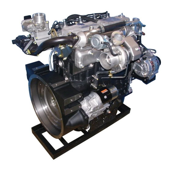
- Page 1 SERVICE MANUAL November 2007 99619-30110 Pub. No. 99619-30110 Printed in Japan Pub. No.
- Page 3 INTRODUCTION This service manual describes the specifications, maintenance and service procedures for Mitsubishi diesel engines. To maintain the performance of the engine for many years and to ensure safe operation, it is important to use the engine correctly and conduct regular inspection and maintenance, and also to take necessary measures which involves the disassembly, inspection, repair and reassembly of the engine and engine parts.
-
Page 5: How To Use This Manual
Mitsubishi Diesel Engine (standard model for land use). A short summary describing the content of each Group is given in the General Contents page, and there is also a detailed table of contents at the beginning of each Group. - Page 6 INTRODUCTION Terms used in this manual Nominal means the rated (design) size or magnitude of a part to be measured. Standard means the quantitative requirement for dimension of a part, clearance between parts and performance. This is given in a form of tolerance.
-
Page 7: Fire And Explosion
INTRODUCTION Safety Cautions Fire and explosion Keep flames away Care about fuel, oil and exhaust gas leakage Store fuel and engine oil in a well If any fuel, oil or exhaust gas leakage is found, immedi- ventilated designated area. ately take corrective measures to stop it. Make sure that the caps of fuel and Such leakages, if left uncorrected, can cause fuel or engine oil containers are tightly... - Page 8 INTRODUCTION Stay clear of all rotating and moving parts Install protective covers on rotating parts Lockout and Tagout Make sure the protective covers for Be sure to lockout and tagout before starting inspection engine rotating parts are properly and maintenance. installed as intended.
- Page 9 INTRODUCTION Be careful of burns Protect ears from noises Do not touch the engine during or immedi- Wear ear plugs ately after operation Always wear ear plugs when enter- Do not touch the engine during or ing the machine room (engine immediately after operation...
- Page 10 Such a way of disposal is strictly prohibited by laws and regulations. Dispose of waste oil, coolant and other environmentally hazardous waste in accordance with the applicable law and regulations, or consult a Mitsubishi dealer.
- Page 11 INTRODUCTION Service battery When abnormality occurs Handle the battery correctly Stop overheated engine after cooling run • Never use flames or allow sparks Even if the engine comes to overheat, do not stop the to generate near the battery. The engine immediately.
- Page 12 INTRODUCTION Other cautions Modification of engine prohibited Warming-up operation Unauthorized modification of the engine will void the After starting the engine, run the engine at low idling manufacturer’s warranty. speeds for 5 to 10 minutes for warming-up. Start the Modification of the engine may not only cause engine work after this operation is completed.
- Page 13 INTRODUCTION Maintenance of air cleaner or pre-cleaner Use of tools optimum for each work The major cause of abnormal wear on engine parts is Always keep in mind to select most appropriate tools dust entering with intake air. Worn parts produce many for the work to be performed and use them correctly.
- Page 14 INTRODUCTION About warning labels Maintenance of warning labels Make sure all warning/caution labels are legible. Clean or replace the warning/caution labels when the description and/or illustration are not clear to read. For cleaning the warning/caution labels, use a cloth, water and soap. Do not use cleaning solvents, gasoline or other chemicals to prevent the letters from getting blurred or the adhesion from being weakened.
-
Page 15: Table Of Contents
GENERAL CONTENTS Group Name Contents Group No. External view System flow diagrams General Engine serial number location Main specifications Tips on disassembling and reassembling Maintenance service data Service data Tightening torque table General tools Service tools Special tools Determining overhaul timing Determination of overhaul Testing compression pressure Disassembling and inspecting cylinder head and valve mechanism... -
Page 17: General
GENERAL 1. External view........1-2 1.1 Model S3Q2 ..........1-2 1.2 Model S3Q2-T.......... 1-3 2. System flow diagrams .....1-4 2.1 Fuel system - flow diagram ...... 1-4 2.2 Lubrication system - flow diagram ... 1-4 2.3 Cooling system - flow diagram....1-5 2.4 Inlet and exhaust system - flow diagram.. -
Page 18: External View
GENERAL 1. External view 1.1 Model S3Q2 Fuel injection nozzle Oil filler Glow plug Inlet manifold Water pump Water drain plug Fuel injection pump Front Rear Stop solenoid Fuel feed pump Flywheel Oil pan Left side of engine Hanger Hanger... -
Page 19: Model S3Q2-T
GENERAL 1.2 Model S3Q2-T Fuel injection nozzle Oil filler Glow plug Inlet manifold Water pump Water drain plug Fuel injection pump Front Rear Stop solenoid Fuel feed pump Flywheel Oil pan Left side of engine Turbocharger Hanger Hanger Exhaust manifold... -
Page 20: System Flow Diagrams
Fuel return pipe To fuel tank Fuel injection pump From fuel tank Fuel feed pump Fuel system - flow diagram 2.2 Lubrication system - flow diagram Turbocharger (S3Q2-T) Valve mechanism Push rod Valve Tappet Piston Relief valve Camshaft Oil main gallery... -
Page 21: Cooling System - Flow Diagram
2.3 Cooling system - flow diagram Thermostat Radiator Bypass pipe Water pump Oil cooler Cooling system - flow diagram 2.4 Inlet and exhaust system - flow diagram Exhaust Inlet Turbocharger (S3Q2-T) Inlet manifold Exhaust manifold Inlet and exhaust system - flow diagram... -
Page 22: Engine Serial Number Location
GENERAL 3. Engine serial number location The engine serial number is stamped on the side of the crankcase. Stamp location of engine serial number... -
Page 23: Main Specifications
GENERAL 4. Main specifications This specifications may differ from your engine specifications. Table 1-1 Main specifications(1 / 3) Engine type S3Q2 S3Q2-T Vertical type, Water-cooled, Model 4-stroke cycle diesel engine Number and arrangement of cylinders 3 cylinder in-line Combustion type... - Page 24 GENERAL Table 1-1 Main specifications(2 / 3) Engine type S3Q2 S3Q2-T Forced circulation type Lubricating method (pressure feed by oil pump) Standard Class CF or CH-4 (API service classification) Engine oil Engine total: approx. 6.4 L [1.69 U.S.gal.] Engine oil capacity (approx.
- Page 25 GENERAL Table 1-1 Main specifications(3 / 3) Engine type S3Q2 S3Q2-T Manufacturer Mitsubishi Electronic Corporation Type M008T70371 Pinion meshing type Pinion shift Output 12 V - 2.0 kW Ring gear and pinion ratio 10/113 Voltage 11 V No-load Current 130 A or below...
-
Page 26: Tips On Disassembling And Reassembling
5. Tips on disassembling and reassem- bling This service manual specifies the recommended procedures to be followed when servicing Mitsubishi engines. The manual also specifies the special tools that are required for the work, and the basic safety precautions to follow when working. - Page 27 SERVICE DATA 1. Maintenance service data ....2-2 1.1 General ............ 2-2 1.2 Basic engine ..........2-2 1.3 Fuel system..........2-7 1.4 Lubrication system ........2-7 1.5 Cooling system ........2-7 1.6 Electrical system ........2-8 2. Tightening torque table ....2-9 2.1 Major bolt tightening torque .....
-
Page 28: Maintenance Service Data
SERVICE DATA 1. Maintenance service data 1.1 General Table 2-1 Maintenance service data table - General Unit: mm [in.] Inspection point Nominal Standard Limit Remark Maximum rotation speed (rated rotation speed used as reference) Varies depending on the specifications Adjust governor setting. Minimum rotation speed When oil and water tempera- 2.94 MPa... - Page 29 SERVICE DATA Table 2-2 Maintenance service data table - Basic engine (2 / 5) Unit: mm [in.] Inspection point Nominal Standard Limit Remark Valve seat angle 30° 0.7 to 0.9 Seat width Valve sinkage [0.031] [0.028 to 0.035] [0.051] 1.18 1.04 to 1.32 Valve seat Seat width...
-
Page 30: Service Data
SERVICE DATA Table 2-2 Maintenance service data table - Basic engine (3 / 5) Unit: mm [in.] Inspection point Nominal Standard Limit Remark ø 28 28.000 to 28.010 Piston pin hole inside diameter [1.10] [1.1024 to 1.1028] ø 28 27.994 to 28.000 Outside diameter [1.10] [1.1021 to 1.1024]... - Page 31 SERVICE DATA Table 2-2 Maintenance service data table - Basic engine (4 / 5) Unit: mm [in.] Inspection point Nominal Standard Limit Remark Major axis Major axis - Major axis - +0.1 Inlet 46.916 minor axis = minor axis = -0.3 +0.004 6.684 [0.2631]...
- Page 32 SERVICE DATA Table 2-2 Maintenance service data table - Basic engine (5 / 5) Unit: mm [in.] Inspection point Nominal Standard Limit Remark ø 58 57.950 to 57.970 Crankpin outside diameter [2.28] [2.2815 to 2.2823] ø 65 64.965 to 64.985 Crankpin journal outside diameter [2.56] [2.5577 to 2.5585]...
-
Page 33: Service Data
SERVICE DATA 1.3 Fuel system Table 2-3 Maintenance service data table - Fuel system Inspection point Nominal Standard Limit Remark 13.73 MPa 13.93 to 14.71 MPa Valve opening pres- {140 kgf/cm²} {142 to 150 kgf/cm²} Standard is a value of new parts. sure [1991 psi] [2020 to 2133 psi]... -
Page 34: Electrical System
SERVICE DATA 1.6 Electrical system Table 2-6 Maintenance service data table - Electrical system Unit: mm [in.] Inspection point Nominal Standard Limit Remark ø 32 31.4 Diameter [1.26] [1.236] 0.10 Commutator Runout [0.004] 0.4 to 0.6 Mica depth [0.0157 to 0.0236] [0.008] Brush leight [0.709]... -
Page 35: Tightening Torque Table
SERVICE DATA 2. Tightening torque table 2.1 Major bolt tightening torque 2.1.1 Basic engine Table 2-7 Tightening torque table - Basic engine Threads Torque Description Dia × Pitch Remark N·m kgf·m lbf·ft (mm) Cylinder head bolt 12 × 1.75 118 ± 5 12 ±... -
Page 36: Lubrication System
SERVICE DATA 2.1.3 Lubrication system Table 2-9 Tightening torque table - Lubrication system Threads Torque Description Dia × Pitch Remark N·m kgf·m lbf·ft (mm) Oil pan 8 × 1.25 8 ± 1 0.8 ± 0.1 6 ± 0.7 Oil pan drain plug 14 ×... -
Page 37: Standard Bolt And Nut Tightening Torque
SERVICE DATA 2.2 Standard bolt and nut tightening torque Table 2-13 Standard bolt and nut tightening torque Threads Width Strength classification Description Dia × Pitch across flats 10.9 (mm) (mm) [in.] N·m kgf·m lbf·ft N·m kgf·m lbf·ft M8 × 1.25 12 [0.47] M10 ×... -
Page 39: Service Tools
SERVICE TOOLS 1. General tools........3-2 2. Special tool........3-3... - Page 40 SERVICE TOOLS 1. General tools General tools Table 3-1 General tool list Tool name Part No. Tool set 32A91-00010 Includes parts No.1 through 10 Tool bag 34491-01102 Spanner F9600-10012 Width across flats: 10 × 12 mm [0.39 × 0.47 in.] Spanner F9600-14017 Width across flats: 14 ×...
-
Page 41: Special Tool
SERVICE TOOLS 2. Special tool Table 3-2 Special tool list (1 / 3) Tool name Part No. Shape Engine compression pressure measuring Compression gauge 33391-02100 0 to 7 MPa {0 to 71.4 kgf/cm²} [0 to 1015.54 psi] Engine compression pressure Gauge adapter 30691-21100 measuring... - Page 42 SERVICE TOOLS Table 3-2 Special tool list (2 / 3) Tool name Part No. Shape Camshaft,thrust plate and rocker Socket 34491-00300 bracket installation Valve guide installer 32C91-00300 Valve guide installation Idler bushing removal/installa- Idler bushing installer 30691-51900 tion Idler bushing puller MH061077 Idler shaft removal Piston ring pliers...
- Page 43 SERVICE TOOLS Table 3-2 Special tool list (3 / 3) Tool name Part No. Shape Front oil seal installer 32C91-00500 Front oil seal installation...
-
Page 45: Determination Of Overhaul
DETERMINATION OF OVERHAUL 1. Determining overhaul timing ...4-2 2. Testing compression pressure ..4-3... -
Page 46: Determining Overhaul Timing
DETERMINATION OF OVERHAUL 1. Determining overhaul timing In most cases, the engine should be overhauled when the compression pressure of the engine becomes low. An increase in engine oil consumption and blow-by gas are also considered to evaluate the engine condition. Besides, such symptoms as a decrease in output, increase in fuel consumption, decrease in oil pressure, difficulty of engine starting and increase in noise are also considered for judging the overhaul timing, although those symptoms are often affected by other causes, and are not always effective to judge the overhaul timing. - Page 47 DETERMINATION OF OVERHAUL 2. Testing compression pressure (a) Be sure to measure the compression pressure for all the cylinders. It is not a good practice to mea- sure the compression pressure for only one cylin- Compression Gauge adapter der, and presume the compression for the gauge P/N:30691-21100 P/N:33391-02100...
- Page 49 DISASSEMBLY OF BASIC ENGINE 1. Disassembling and inspecting cylinder head and valve mechanism ....5-2 1.1 Removing rocker shaft assembly..... 5-3 1.2 Disassembling rocker shaft assembly..5-3 1.3 Removing cylinder head assembly ..5-3 1.4 Removing valve and valve spring .... 5-4 1.5 Removing valve stem seal .......
-
Page 50: Disassembling And Inspecting Cylinder Head And Valve Mechanism
DISASSEMBLY OF BASIC ENGINE 1. Disassembling and inspecting cylinder head and valve mechanism Replace Worn valve cap contact surface, clogged oil holes, worn bushings Damaged threads, worn rod contact surface Fatigue, damage Wear, clogged oil holes Wear at both ends, deflection Wear Crack, carbon deposits, water scale adhesion... -
Page 51: Removing Rocker Shaft Assembly
DISASSEMBLY OF BASIC ENGINE 1.1 Removing rocker shaft assembly Always loosen shorter bolts first. Failing to do so may cause the damage to the rocker shaft bracket. (1) Loosen the rocker arm adjusting screws by rotating about one turn. (2) Loosen the shorter rocker bracket bolts first. (3) Then, loosen the longer rocker bracket bolts. -
Page 52: Removing Valve And Valve Spring
DISASSEMBLY OF BASIC ENGINE 1.4 Removing valve and valve spring Using a valve spring pusher, compress the valve spring Valve spring pusher P/N:30691-04500 evenly and remove the valve cotters. Note: If valves are reusable, mark each valve seat and the mating valve guide for identifying their original positions. -
Page 53: Measuring Piston Protrusion
DISASSEMBLY OF BASIC ENGINE 1.7 Measuring piston protrusion Piston protrusion must always meet the standard, as the amount of protrusion not only influences on the engine performance, but also it is important to prevent valve interference. Measure the protrusion of each piston following the instructions below. -
Page 54: Disassembling And Inspecting Flywheel
DISASSEMBLY OF BASIC ENGINE 2. Disassembling and inspecting flywheel Replace Crack, abnormality of knock hole Replace Steaks on wear surface, stepped wear, cracks, ring gear damage, abnormal wear Disassembling and inspecting flywheel Disassembling sequence 1 Flywheel 3 Oil seal 5 Gasket 2 Oil seal case 4 Rear plate... -
Page 55: Removing Flywheel
DISASSEMBLY OF BASIC ENGINE 2.1 Removing flywheel (a) Be careful not to cut yourself with the ring gear when pulling out the flywheel. Be careful not to drop or hit the flywheel when removing. (b) The personnel who holds the pulley must pay due attention to safety. -
Page 56: Disassembling And Inspecting Timing Gear, Camshaft And Oil Pan
DISASSEMBLY OF BASIC ENGINE 3. Disassembling and inspecting timing gear, camshaft and oil pan Replace Damage, wear Flaking, uneven contact, damage, abnormal key groove condition Crack, abnormality of knock hole Clogged oil holes, Wear Wear Replace Replace Worn belt groove, worn oil seal contact surface Disassembling and inspecting timing gear, camshaft and oil pan... -
Page 57: Removing Crankshaft Pulley
DISASSEMBLY OF BASIC ENGINE 3.1 Removing crankshaft pulley The bar that stops the the crankshaft from turning may come off. Pay due attention to safety. (1) Screw two guide bolts into the threaded holes at the rear end of the crankshaft. Stick a bar across the guide bolts to prevent the crankshaft from turning. -
Page 58: Measuring Idler Gear End Play
DISASSEMBLY OF BASIC ENGINE 3.4 Measuring idler gear end play Using a feeler gauge or dial gauge, measure the end play of idler gear. If the measured value exceeds the limit, replace the idler gear with the new gear. Item Standard Limit 0.05 to 0.20 mm... -
Page 59: Removing Oil Pan And Oil Pan Gasket
DISASSEMBLY OF BASIC ENGINE 3.8 Removing oil pan and oil pan gasket (1) Remove the bolts from the oil pan, and remove the oil pan from crankcase. (2) Remove the oil pan gasket from crankcase. Removing oil pan and oil pan gasket 3.9 Removing oil pump Remove the oil pump set bolts, and pull out the oil pump from crankcase. -
Page 60: Disassembling And Inspecting Piston, Connecting Rod, Crankshaft And Crankcase
DISASSEMBLY OF BASIC ENGINE 4. Disassembling and inspecting piston, connecting rod, crankshaft and crankcase Adhesion of water scale, corrosion, Wear, damage flaking Surface scratches, cracks, damage, wear, carbon deposits Fatigue Wear Wear, clogged oil holes Cracks, clogged oil holes Damaged threads Wear Serration for cracks, wear Scratches,... -
Page 61: Laying Crankcase On Its Side
DISASSEMBLY OF BASIC ENGINE 4.1 Laying crankcase on its side Attach the wire rope to the crankcase. By using a crane, hoist the crankcase and lay it with its side faced downwards. Layin crankcase on its side 4.2 Measuring connecting rod end play (1) Measure the clearance (end play) between the connecting rod big-end and crankshaft by using the thickness gauge. -
Page 62: Removing Carbon Deposits From The Upper Part Of Cylinder
DISASSEMBLY OF BASIC ENGINE 4.4 Removing carbon deposits from the upper part of cylinder Be sure to remove carbon deposits from the upper part of the cylinder before removing the piston, as they could cause damage to the piston and piston ring. Remove carbon deposits from the upper part of cylinder using a cloth or oil paper. -
Page 63: Uprearing Crankcase
DISASSEMBLY OF BASIC ENGINE 4.8 Uprearing crankcase Uprear the crankcase softly with its upper faced downward. Positioning crankcase 4.9 Measuring crankshaft end play (1) With attach the dial gauge to top of the crankshaft, measure the end play. (2) If measured value exceeds the limit, replace the flange bearing with new one. -
Page 64: Removing Crankshaft
DISASSEMBLY OF BASIC ENGINE 4.11 Removing crankshaft Be careful not to damage bearings when removing the crankshaft. (1) Slowly lift the crankshaft straight up. (2) Arrange the bearings in the order of disassembly so that their original positions are restored when reassembling. Note: (a) When raising the crankshaft, do not allow wire chain to come into contact with the crankshaft. - Page 65 INSPECTION AND REPAIR OF BASIC ENGINE 1. Inspecting and repairing cylinder head 4.5 Measuring clearance between connecting rod and valve mechanism .....6-2 bushing and piston pin ......6-14 1.1 Measuring distortion of the bottom surface of 4.6 Replacing connecting rod bushing ..6-15 the cylinder head........
-
Page 66: Inspecting And Repairing Cylinder Head And Valve Mechanism
INSPECTION AND REPAIR OF BASIC ENGINE 1. Inspecting and repairing cylinder head and valve mechanism 1.1 Measuring distortion of the bottom surface of the cylinder head With a straight edge placed on the bottom face of the cylinder head, measure the bottom face distortion using a feeler gauge. -
Page 67: Measuring Push Rod Runout
INSPECTION AND REPAIR OF BASIC ENGINE 1.4 Measuring push rod runout Measure the runout of push rod. If the standard value is exceeded, replace the push rod. Item Standard Remark Pushrod Push rod 0.3 mm Total indicated reading runout [0.012 in.] or less (TIR) 1/2L 1/2L... -
Page 68: Replacing Valve Guide
INSPECTION AND REPAIR OF BASIC ENGINE 1.6 Replacing valve guide Valve guide remover P/N:32A91-00300 Because valve guides must be inserted to the speci- fied amount, be sure to use a valve guide installer. (1) To remove valve guides, use a valve guide remover. Valve guide Pulling out valve guide (2) To press-fit valve guides, use a valve guide installer. -
Page 69: Inspecting Valve Face
INSPECTION AND REPAIR OF BASIC ENGINE 1.7 Inspecting valve face Apply a thin coat of Shinmyoutan or equivalent lead-free coloring paste on the valve face, and strike the valve face against the valve seat using a valve lapper to check for Valve lapper contact condition. -
Page 70: Replacing Valve Seat
INSPECTION AND REPAIR OF BASIC ENGINE 1.8 Replacing valve seat (1) To remove the valve seat, weld a stud to the valve seat as illustrated. Then, insert a rod into the valve guide Weld Shaft hole from the top of the cylinder head, and press out the valve seat with the rod. -
Page 71: Refacing Valve Seat
INSPECTION AND REPAIR OF BASIC ENGINE 1.10 Refacing valve seat (1) Use the valve seat cutter or valve seat grinder to reface the valve seat. After refacing, sand the valve seat lightly using 400 grit sandpaper, inserting it between the cutter and valve seat. -
Page 72: Removing Combustion Jet
INSPECTION AND REPAIR OF BASIC ENGINE 1.12 Removing combustion jet Replace the combustion jet only when it has defect as crack. Round rod (1) Insert a round bar (approx; ø6 mm [0.24 in.]) into glow (ø6 mm [0.24 in.]) plug hole, and tap the combustion jet inner face perimeter lightly to pull out the combustion jet. -
Page 73: Inspecting And Repairing Flywheel
INSPECTION AND REPAIR OF BASIC ENGINE 2. Inspecting and repairing flywheel 2.1 Inspecting ring gear Inspect the ring gear for a missing tooth or worn teeth, and Flywheel if defects are found, replace the ring gear. Ring gear 2.2 Replacing ring gear 2.2.1 Removing ring gear (1) Heat the ring gear evenly using an acetylene torch or... -
Page 74: Inspecting And Repairing Timing Gear, Camshaft And Oil Pan
INSPECTION AND REPAIR OF BASIC ENGINE 3. Inspecting and repairing timing gear, camshaft and oil pan 3.1 Inspecting V-pulley Check the V-belt groove of the pulley for wear. Attach a new V-belt around a worn pulley, apply a high tension to the belt, and check whether the top surface of the belt is outside or inside of the pulley groove to determine the degree of 1.6 mm [0.06 in.]... -
Page 75: Replacing Idler Shaft
INSPECTION AND REPAIR OF BASIC ENGINE 3.5 Replacing idler shaft To remove the idler shaft, use the idler shaft puller. Idler shaft puller Note: When installing the idler shaft into the crankcase, P/N:MH061077 orient the idler shaft so that its oil hole faces the upper crankcase. -
Page 76: Measuring Camshaft Runout
INSPECTION AND REPAIR OF BASIC ENGINE 3.8 Measuring camshaft runout Measure the camshaft runout using a dial gauge. If the limit is exceeded, correct the camshaft using a press, or replace the camshaft with a new one. Note: With a dial gauge set on the camshaft, rotate the camshaft one turn and read the gauge indication. -
Page 77: Inspecting And Repairing Piston, Connecting Rod, Crankshaft And Crankcase
B mark Symbol Symbol size size Piston Piston S3Q2 S3Q2-T weight mark weight mark Piston weight stamp location 4.2 Measuring piston ring groove No.1 compression ring Remove carbon deposits from pistons and check the entire circumference of the piston. -
Page 78: Measuring Piston Ring End Gap
INSPECTION AND REPAIR OF BASIC ENGINE 4.3 Measuring piston ring end gap Place the piston rings in a gauge or a new cylinder liner, and measure the gap of each ring with feeler gauges. If the limit Sickness gauge is exceeded, replace all the rings as a set. Note: Using a piston, push the piston ring squarely into the gauge or the cylinder liner. -
Page 79: Replacing Connecting Rod Bushing
INSPECTION AND REPAIR OF BASIC ENGINE 4.6 Replacing connecting rod bushing Use a connecting rod bushing installer to replace the Match marks side connecting rod bushing. (1) With the bushing joints oriented as shown in the illustration, align the oil hole of bushing with the oil Oil hole hole of connecting rod, and press-fit the connecting rod bushing into the connecting rod. -
Page 80: Inspecting Oil Clearance Of Connecting Rod Bearing
INSPECTION AND REPAIR OF BASIC ENGINE 4.8 Inspecting oil clearance of connecting rod bearing Tightening torque Measuring Measuring 54 ± 5 N·m directions points (1) Install the bearing to the connecting rod big end. After {5.5 ± 0.5 kgf·m} [40 to 3.6 lbf·ft] tightening the connecting rod cap with the specified torque, measure the inside diameter of the bearing. -
Page 81: Inspecting Oil Clearance Of Main Bearing
INSPECTION AND REPAIR OF BASIC ENGINE 4.9 Inspecting oil clearance of main bearing (1) Install the main bearing and the main bearing cap to the crankcase. After tightening the main bearing cap with the specified torque, measure the bearing inside diameter. -
Page 82: Inspecting Oil Seal Contact Surface
INSPECTION AND REPAIR OF BASIC ENGINE 4.10 Inspecting oil seal contact surface Inspect the oil seal contact surface located on the crankshaft rear part. If the crankshaft wears due to the oil seal, replace the oil seal and the oil seal sleeve with new spare parts. Oil seal Oil seal sleeve Installing front oil seal (1) -
Page 83: Measuring Crankshaft Runout
INSPECTION AND REPAIR OF BASIC ENGINE 4.11 Measuring crankshaft runout Support the crankshaft at the front and rear journals with V- blocks, and measure the crankshaft runout at the center journal using a dial gauge. If the runout deviates from the standard only slightly, grind the crankshaft to repair. -
Page 84: Measuring Cylinder Inside Diameter
INSPECTION AND REPAIR OF BASIC ENGINE 4.14 Measuring cylinder inside diameter Use a cylinder gauge to measure the inside diameter and cylindericity of the cylinder at three locations in the A and B Measuring directions as shown in the illustration. directions If any one of the cylinders exceeds the repair limit, bore all the cylinders and replace the pistons and piston rings with... -
Page 85: Measuring Crankcase Top Surface Distortion
INSPECTION AND REPAIR OF BASIC ENGINE 4.15 Measuring crankcase top surface distor- tion Refacing of cylinder head should be kept to an abso- lute minimum. Excessive grinding of the cylinder head may result in defects such as defective combustion and stamping (contact between piston and valve). -
Page 86: Inspecting Piston Cooling Nozzle
INSPECTION AND REPAIR OF BASIC ENGINE 4.18 Inspecting piston cooling nozzle Insert the round bar (ø4 mm [0.1575 in.] or less) to the top of the piston cooling nozzle installed on the crankcase. Round rod Inspect that the steal ball operates smoothly. If it does not operated smoothly, replace the piston cooling nozzle with new one. - Page 87 REASSEMBLY OF BASIC ENGINE 1. Reassembling piston, connecting rod, crankshaft and crankcase ....7-2 1.1 Installing tappet........7-2 1.2 Installing main bearing ......7-2 1.3 Installing crankshaft ......... 7-2 1.4 Installing main bearing cap ...... 7-3 1.5 Installing main bearing cap bolt ....7-3 1.6 Measuring crankshaft end play ....
-
Page 88: Reassembling Piston, Connecting Rod, Crankshaft And Crankcase
REASSEMBLY OF BASIC ENGINE 1. Reassembling piston, connecting rod, crankshaft and crankcase 1.1 Installing tappet (1) Apply the engine oil to the tappet, and insert it to the Apply engine oil tappet hole on the crankcase. (2) Make sure that the tappet rotates smoothly. Installing tappet 1.2 Installing main bearing (1) Install the main bearings (upper and lower) with... -
Page 89: Installing Main Bearing Cap
REASSEMBLY OF BASIC ENGINE 1.4 Installing main bearing cap Front mark The foremost and rearmost caps should be installed so that they are flush with the crankcase surface. Engine front side Install the main bearing caps so that their front marks (arrow) and cap numbers are in numerical order from the front of the engine. -
Page 90: Measuring Crankshaft End Play
REASSEMBLY OF BASIC ENGINE 1.6 Measuring crankshaft end play (1) Measure the crankshaft end play. (2) If the measured end play is small, loosen the cap bolt and retighten it. (3) If the measured value exceeds the limit, replace the flange bearing with new one. -
Page 91: Installing Piston Ring
REASSEMBLY OF BASIC ENGINE 1.8 Installing piston ring Top mark No.1 Every piston ring has a top mark such as “R” near the compression end gap. Install all piston rings with this mark facing ring upward. No.2 No.1, No.2 If the rings are installed upside down, it could cause compression ring malfunctions such as excessive oil consumption or an... -
Page 92: Installing Connecting Rod Bolt And Connecting Rod Bearing
REASSEMBLY OF BASIC ENGINE 1.10 Installing connecting rod bolt and connect- ing rod bearing Lug groove (1) Press fit the connecting rod bolts into the connecting rod. Note: When press fitting the bolt, make sure that the bolt fully contacts its seating position without any interference with the shoulder of mounting surface. -
Page 93: Installing Connecting Rod Cap
REASSEMBLY OF BASIC ENGINE 1.12 Installing connecting rod cap (1) Fit the connecting rod bearing (lower) to the rod cap with the lug aligned with the lug groove, and apply the Lug groove engine oil inside the bearing. (2) Install the connecting rod cap to the connecting rod (crankpin) with its match mark facing on the same side as the match mark on the connecting rod. -
Page 94: Reassembling Timing Gear, Camshaft And Oil Pan
REASSEMBLY OF BASIC ENGINE 2. Reassembling timing gear, camshaft and oil pan 2.1 Installing front plate (1) Clean the mounting surface of the gasket. Apply the sealant and spread it evenly. (2) According to need, apply the sealant to prevent the gasket falling off. -
Page 95: Installing Oil Pan
REASSEMBLY OF BASIC ENGINE 2.4 Installing oil pan Clean the both side of the oil pan gasket contact surfaces 8 ± 1 N·m {0.8 ± 0.1 kgf·m} and the contact surfaces of other parts thoroughly. Approx. 5 mm [6 ± 0.7 lbf·ft] (1) Apply the sealant (ThreeBond 1212) to the mating [0.20 in.] surface clearance of the No,1 and 4 main bearings and... -
Page 96: Installing Front Idler Gear
REASSEMBLY OF BASIC ENGINE 2.6 Installing front idler gear (1) Apply engine oil to the idler gear shaft. (2) Install the idler gear with all match marks on it aligned with the marks on the other gears. (3) Install the thrust plate with its hole matching the pin of the idler gear shaft. -
Page 97: Installing Timing Gear Case
REASSEMBLY OF BASIC ENGINE 2.9 Installing timing gear case (1) Install the baffle plate to the crankcase. (2) Install the gasket and the timing gear case to the 40 mm [1.57 in.] crankcase aligning with the dowel pin located on the crankcase front side. -
Page 98: Reassembling Flywheel
REASSEMBLY OF BASIC ENGINE 3. Reassembling flywheel 3.1 Installing rear plate (1) Install a new rear plate gasket. Crank case (2) Install the rear plate aligning with the dowel pins. Gasket Rear plate Tighten the mounting bolt to the specified torque. Note: Install the starter to the rear plate in advance to facilitate the subsequent reassembly. -
Page 99: Reassembling Cylinder Head And Valve Mechanism
REASSEMBLY OF BASIC ENGINE 4. Reassembling cylinder head and valve mechanism 4.1 Installing valve stem seal Stem seal installer P/N:32C91-10400 Do not apply oil or liquid gasket to the inner side of stem seal that comes in contact with the valve guide. (1) Apply engine oil to the lip of new valve stem seal. -
Page 100: Installing Cylinder Head Assembly
REASSEMBLY OF BASIC ENGINE 4.4 Installing cylinder head assembly Install the cylinder head on the crankcase by aligning it with the dowel pins. Note: Be careful not to displace the cylinder gasket when installing. Dowel pin Dowel pin Installing cylinder head 4.5 Tightening cylinder head bolts In the numerical order as shown in the illustration, tighten cylinder head bolts progressively to the specified torque. -
Page 101: Installing Rocker Shaft Assembly
REASSEMBLY OF BASIC ENGINE 4.8 Installing rocker shaft assembly (1) Install the valve caps to the valve heads. Tightening torque long: (2) Tighten the long bolts of the rocker bracket to the 15 ± 2 N·m specified torque. {1.5 ± 0.2 kgf·m} [11 ±... - Page 103 FUEL SYSTEM 1. Removing fuel system.....8-2 1.1 Removing fuel injection pump....8-3 2. Disassembling, inspecting and reassembling fuel system....8-4 2.1 Disassembling and inspecting fuel injection nozzle............8-4 2.1.1 Inspecting and adjusting fuel injection valve opening pressure ........8-5 2.1.2 Inspecting fuel spray pattern of fuel injection nozzle ............8-6 2.1.3 Cleaning and replacing faulty nozzle ..8-6 2.1.4 Reassembling fuel injection nozzle ....8-7...
-
Page 104: Removing Fuel System
FUEL SYSTEM 1. Removing fuel system Replace Replace Replace Replace Removing fuel system Removing sequence 1 Fuel return pipe 7 Oil pipe 2 No.1 fuel injection pipe 8 Pump bracket 3 No.2 fuel injection pipe 9 Injection pump gear 4 No.3 fuel injection pipe 10 Injection pump flange 5 fuel leak-off pipe 11 Fuel injection pump... -
Page 105: Removing Fuel Injection Pump
FUEL SYSTEM 1.1 Removing fuel injection pump (1) Check the match mark location of the fuel injection pump flange and fuel injection pump installation flange. (2) Remove the engine front cover. (3) Put the match mark on the fuel injection pump gear and the idler gear. -
Page 106: Disassembling, Inspecting And Reassembling Fuel System
FUEL SYSTEM 2. Disassembling, inspecting and reassembling fuel system 2.1 Disassembling and inspecting fuel injection nozzle Wear Settling, breakage Wear, damage Carbon deposit, nozzle hole clogging Disassembling and inspecting fuel injection nozzle Disassembling sequence 1 Nozzle retaining nut 5 Spring 2 Nozzle tip assembly 6 Water 3 Piece... -
Page 107: Inspecting And Adjusting Fuel Injection Valve Opening Pressure
FUEL SYSTEM 2.1.1 Inspecting and adjusting fuel injection valve opening pressure Nozzle tester Never touch the spray hole during injection (1) Mount the nozzle on the nozzle tester. (2) Pump the tester handle at a rate of approximately one cycle per second while observing the pressure at which injection starts. -
Page 108: Inspecting Fuel Spray Pattern Of Fuel Injection Nozzle
FUEL SYSTEM 2.1.2 Inspecting fuel spray pattern of fuel injec- tion nozzle Defective spray pattern (1) When adjusting the nozzle opening pressure using a nozzle tester, check for clogged nozzle hole, fuel spray pattern, and fuel dribble from the spray hole. (2) Checking points of fuel spray pattern are as follows: ·... -
Page 109: Reassembling Fuel Injection Nozzle
FUEL SYSTEM 2.1.4 Reassembling fuel injection nozzle Tightening torque: 36.8 ± 2.45 N·m {3.75 ± 0.25 kgf·m} [27 ± 1.8 lbf·ft] Tightening torque: 59 ± 6 N·m {6 ± 0.6 kgf·m} [43 ± 4.3 lbf·ft] Reassembling fuel injection nozzle... -
Page 110: Installing Fuel System
FUEL SYSTEM 3. Installing fuel system 23 ± 2 N·m {2.3 ± 0.2 kgf·m} [16.6 ± 1.4 lbf·ft] 59 ± 6 N·m 29 ± 3 N·m Replace {6 ± 0.6 kgf·m} {3 ± 0.3 kgf·m} [43 ± 4.3 lbf·ft] [22 ± 2.2 lbf·ft] Replace 20 ±... - Page 111 LUBRICATION SYSTEM 1. Removing lubrication system ..9-2 1.1 Removing and inspecting oil cooler and relief valve............9-2 1.2 Removing and inspecting oil pan, oil pump, oil pressure switch ........9-3 1.3 Removing and inspecting oil pipe and oil separator..........9-4 2.
-
Page 112: Removing Lubrication System
LUBRICATION SYSTEM 1. Removing lubrication system 1.1 Removing and inspecting oil cooler and relief valve Spring for fatigue and damage Replace Replace Replace Replace Clogging, deformation, damage Replace Replace Replace Removing and inspecting oil cooler and relief valve Removing sequence 1 Plug 5 Rebber hose 9 Connector... -
Page 113: Removing And Inspecting Oil Pan, Oil Pump, Oil Pressure Switch
LUBRICATION SYSTEM 1.2 Removing and inspecting oil pan, oil pump, oil pressure switch Replace Replace Replace Removing and inspecting oil pan, oil pump, oil pressure switch Removing sequence 1 Oil pan 3 Oil pump 2 Oil pan gasket 4 Oil pressure switch... -
Page 114: Removing And Inspecting Oil Pipe And Oil Separator
LUBRICATION SYSTEM 1.3 Removing and inspecting oil pipe and oil separator Replace Replace Replace Replace Replace Replace Replace Replace Replace Removing and inspecting oil pipe and oil separator Removing sequence 1 Oil pipe 6 Breather hose 11 Spacer 2 Oil hose 7 Breather hose 12 Oil separator 3 Oil return pipe... -
Page 115: Disassembling, Inspecting And Reassembling Lubrication System
LUBRICATION SYSTEM 2. Disassembling, inspecting and reassembling lubrication system 2.1 Disassembling and inspecting oil pump Gear defect, wear Replace Disassembling and inspecting oil pump Disassembling sequence 1 Oil strainer 2 Oil pump cover 3 Oil pump 2.2 Measuring clearance between outer rotor and inner rotor Measure the clearance between the outer rotor and the inner rotor. -
Page 116: Measuring End Play Of Rotor And Pump Case
LUBRICATION SYSTEM 2.3 Measuring end play of rotor and pump case Measure the end play of the rotor and the pump case. If measured value exceeds the limit, replace the oil pump with new one. Item Standard Limit End play of rotor and 0.04 to 0.09 mm 0.15 mm pump case... -
Page 117: Installing Lubrication System
LUBRICATION SYSTEM 3. Installing lubrication system 3.1 Installing oil pan, oil pump and oil pressure switch Replace 34 ± 4 N·m {3.5 ± 0.4 kgf·m} [25 ± 2.9 lbf·ft] 29.4 N·m {3.0 kgf·m} [22 lbf·ft] Replace 39 ± 5 N·m {4 ±... -
Page 118: Installing Oil Cooler And Relief Valve
LUBRICATION SYSTEM 3.2 Installing oil cooler and relief valve 49 ± 5 N·m {5 ± 0.5 kgf·m} [36 ± 3.6 lbf·ft] Replace Replace Replace Replace 69 ± 10 N·m {7 ± 1 kgf·m} [51 ± 7.2 lbf·ft] Replace Replace Replace Installing oil cooler and relief valve... -
Page 119: Installing Oil Pipe And Oil Separator
LUBRICATION SYSTEM 3.3 Installing oil pipe and oil separator Replace Replace Replace Replace Replace Replace Replace Replace Replace Installing oil pipe and oil separator... - Page 121 COOLING SYSTEM 1. Removing cooling system .....10-2 2. Disassembling, inspecting and reassembling cooling system ..10-3 2.1 Disassembling, inspecting and reassembling water pump ..........10-3 2.1.1 Inspecting water pump for smooth rotation10-3 2.2 Disassembling, inspecting and reassembling thermostat ..........10-4 2.2.1 Inspecting thermostat .......10-4 3.
-
Page 122: Removing Cooling System
COOLING SYSTEM 1. Removing cooling system Replace Crack, damage Cracked, distortion, damage Replace Cracked, elongation, wear, damage, aging Crack, water leakage, damage Cracked, distortion, damage Removing cooling system Removing sequence 1 Cooling fan 4 Water pump pulley 2 Fan spacer 5 Water pump assembly 3 V-belt 6 Thermostat... -
Page 123: Disassembling, Inspecting And Reassembling Cooling System
COOLING SYSTEM 2. Disassembling, inspecting and reassembling cooling system 2.1 Disassembling, inspecting and reassembling water pump 10 ± 1.0 N·m Crack, water leakage, distortion {1.0 ± 0.1 kgf·m} [7.2 ± 0.7 lbf·ft] Replace Crack, water leakage, damage, impeller and shaft of rotation Replace Disassembling, inspecting and reassembling water pump Disassembling sequence... -
Page 124: Disassembling, Inspecting And Reassembling Thermostat
COOLING SYSTEM 2.2 Disassembling, inspecting and reassembling thermostat 18 ± 2 N·m {1.8 ± 0.2 kgf·m} [13.0 ± 1.4 lbf·ft] Replace Disassembling, inspecting and reassembling thermostat Disassembling sequence 1 Thermostat cover 3 Thermostat 2 Gasket 4 Thermostat case 2.2.1 Inspecting thermostat Be careful of burns or a fire when measuring tempera- [0.32] ture, as it involves a high-temperature and open flame. -
Page 125: Installing Cooling System
COOLING SYSTEM 3. Installing cooling system Replace Replace Replace Installing cooling system 10-5... - Page 127 INLET AND EXHAUST SYSTEMS 1. Removing inlet and exhaust sysytem .........11-2 2. Inspecting inlet and exhaust system ...........11-3 2.1 Measuring exhaust manifold distortion .. 11-3 3. Installing inlet and exhaust system11-4 11-1...
-
Page 128: Removing Inlet And Exhaust Sysytem
INLET AND EXHAUST SYSTEMS 1. Removing inlet and exhaust sysytem Replace Replace Replace Replace Replace The illustration is an example of S3Q2-T Removing inlet and exhaust sysytem Removing sequence 1 Air hose 4 Air inlet elbow 2 Air hose 5 Inlet manifold... -
Page 129: Inspecting Inlet And Exhaust System
INLET AND EXHAUST SYSTEMS 2. Inspecting inlet and exhaust system 2.1 Measuring exhaust manifold distortion (1) Check the flange for crack. (2) Check the flange suface for distortion. If the distortion exceeds the standard, retouch the surface. Item Standard Less than 0.15 mm Exhaust manifold distortion [0.0059 in.] Measuring exhaust manifold distortion... -
Page 130: Installing Inlet And Exhaust System
7 ± 1 N·m {0.7 ± 0.1 kgf·m} [5 ± 0.7 lbf·ft] Replace 7 ± 1 N·m {0.7 ± 0.1 kgf·m} [5 ± 0.7 lbf·ft] Replace Replace Replace The illustration is an example of S3Q2-T Installing inlet and exhaust system 11-4... - Page 131 ELECTRICAL SYSTEM 1. Removing electrical system ..12-2 2.6.9 Reassembling alternator......12-18 1.1 Removing starter........12-2 2.7 Inspecting glow plug......12-19 1.2 Inspection before removing alternator ... 12-2 1.2.1 Inspecting alternator operation....12-2 3. Installing electrical system ..12-20 1.2.2 Handling precaution .........12-2 1.2.3 Inspecting regulated voltage ....12-3 1.2.4 Inspecting output ........12-3 1.3 Removing alternator.......
-
Page 132: Removing Electrical System
ELECTRICAL SYSTEM 1. Removing electrical system 1.1 Removing starter Disconnect the harness. Remove the starter mounting bolt and remove the starter. Starter Removing starter 1.2 Inspection before removing alternator 1.2.1 Inspecting alternator operation Locate the cause of faulty charging from malfunctions described below. -
Page 133: Inspecting Regulated Voltage
ELECTRICAL SYSTEM 1.2.3 Inspecting regulated voltage (1) Disconnect the battery (+) terminal, and connect an Ammeter ammeter. (2) Connect a volt meter to terminal L ground line. (3) Make sure that the volt meter indicates 0 when the Switch starter switch is OFF position. Make sure that the volt meter indicates much lower Battery voltage than battery voltage when the starter switch is... -
Page 134: Removing Alternator
ELECTRICAL SYSTEM 1.3 Removing alternator Rotaion Elongation of belt, degradation, cracked Removing alternator Removal sequence 1 Harness 3 Adjusting plate 5 Alternator bracket 2 V-belt 4 Alternator 12-4... -
Page 135: Removing Glow Plug
ELECTRICAL SYSTEM 1.4 Removing glow plug Removing glow plug Removing sequence 1 Nut 2 Connection plate 3 Glow plug 12-5... -
Page 136: Disassembling, Inspecting And Reassembling Electrical System
ELECTRICAL SYSTEM 2. Disassembling, inspecting and reassembling electrical system 2.1 Inspection before disassembling starter 2.1.1 Inspecting magnetic switch Perform the inspection as described below. If faulty, replace the magnetic switch with a new one. Switch Do not apply current continuously for longer than 10 seconds. -
Page 137: No Load Test
ELECTRICAL SYSTEM 2.1.2 No load test Use as thick a wire as possible and firmly tighten each Ammeter terminal. Switch When detecting the rotation at the tip of the pinion, be Switch careful, as the pinion pops out during operation. Volt meter (1) Connect the starter to the circuit as shown in the Starter... -
Page 138: Disassembling And Inspecting Starter
ELECTRICAL SYSTEM 2.2 Disassembling and inspecting starter Magnet switch open circuit,short Looseness, abnormal noise and rotation condition of bearing Bend, deflection, open circuit and short of armature Pinion gear wear Looseness, abnormal noise and rotation condition of bearing Replace Replace Wear Yoke open circuit, short... -
Page 139: Inspecting And Repairing Starter
ELECTRICAL SYSTEM 2.3 Inspecting and repairing starter 2.3.1 Inspecting brushes for wear Measure the length of the brushes. If the measured value is less than the limit, replace both the brush holder assembly Brush and the brush assembly with new ones. Item Standard Limit... -
Page 140: Measuring Commutator Radial Runout
ELECTRICAL SYSTEM 2.3.4 Measuring commutator radial runout (1) Inspect the commutator surface. If the surface is rough, polish it using a 400 to 600 grit sandpaper. (2) Measure the commutator radial runout with a dial gauge. If the measured value exceeds the limit, replace the armature with a new one. -
Page 141: Inspecting Overrunning Clutch
ELECTRICAL SYSTEM 2.3.9 Inspecting overrunning clutch Do not clean the overrunning clutch in wash oil. Make sure that, when attempting to turn the overrunning clutch, it locks in one direction and rotates smoothly in the opposite direction. Inspecting overrunning clutch 2.3.10 Inspecting continuity of magnetic switch (between M terminal and case) Terminal B... -
Page 142: Reassembling Starter
ELECTRICAL SYSTEM 2.4 Reassembling starter 2.4.1 Applying grease To avoid mixing of different greases, remove old grease before applying new grease. Make sure that the starter mounting surface, brushes, commutator and other electric current conducting compo- nents are free from grease. When overhauling the starter, apply grease to the following sliding surfaces, gears and bearings. -
Page 143: Inspecting And Adjusting After Reassembling
ELECTRICAL SYSTEM 2.5 Inspecting and adjusting after reassembling 2.5.1 Inspecting pinion clearance Do not apply current continuously for longer than 10 seconds. Terminal S (1) Since connecting the wires of the reassembled starter as shown in the diagram causes the pinion to extends and Battery rotate slowly, disconnect the connector from terminal Terminal M... -
Page 144: Disassembling, Inspecting And Reassembling Alternator
ELECTRICAL SYSTEM 2.6 Disassembling, inspecting and reassembling alternator Dirt, damage and seizure of Rotation slip ring, and coil resistance Crack, damage Crack, damage Rotation Short cincuit and open circuit Deformation and damage Sliding state and wear of brushes Broken wire and ground of coil Disassembling, inspecting and reassembling alternator Disassembling sequence... -
Page 145: Separating Front Bracket From Stator
ELECTRICAL SYSTEM 2.6.1 Separating front bracket from stator Do not disassemble the alternator unless the repair is necessary. Do not insert the screwdrivers too deep, as it can dam- age the stator. (1) Remove the through bolts. (2) With two flat-head screwdrivers inserted between the front bracket and stator, pry them apart. -
Page 146: Inspecting Rectifier
ELECTRICAL SYSTEM 2.6.4 Inspecting rectifier Check that diodes in a rectifier function properly. To check, measure both negative (-) and positive (+) resistance alternately twice. If both infinite negative and infinite positive resistances are observed, the diode is open- circuited. If measured value is close to 0 Ω, the diode is short-circuited. -
Page 147: Inspecting Stator
ELECTRICAL SYSTEM 2.6.6 Inspecting stator (1) Checking continuity between lead wires Check that there is continuity between a pair of lead wires. Also check that there is no continuity between a pair of lead wires and other pair of lead wires. If defective, replace the stator. -
Page 148: Replacing Brushes
ELECTRICAL SYSTEM 2.6.8 Replacing brushes (1) To remove the brush and the spring, unsolder the brush Soldering lead. Replacing brushes (2) To install a new brush, push the brush into the brush holder as shown in the illustration, and then solder the lead to the brush. - Page 149 ELECTRICAL SYSTEM 2.7 Inspecting glow plug Check continuity between the terminal and the body as shown in the illustration. If no continuity is indicated, or the resistance is large, replace the glow plug with a new one. Item Standard 1.0 Ω Resistance value Inspecting glow plug 12-19...
-
Page 150: Installing Electrical System
ELECTRICAL SYSTEM 3. Installing electrical system 1.3 ± 0.2 N·m {0.13 ± 0.02 kgf·m} [0.9 ± 0.1 lbf·ft] 18 ± 2 N·m {1.8 ± 0.2 kgf·m} [13 ± 1.4 lbf·ft] Terminal B 11 ± 1 N·m {1.1 ± 0.1 kgf·m} [8 ±... - Page 151 ADJUSTMENT AND OPERATION 1. Adjusting engine......13-2 1.1 Inspecting and adjusting valve clearance13-2 1.1.1 Inspecting valve clearance .......13-2 1.1.2 Adjusting valve clearances.......13-2 1.2 Inspecting and adjusting fuel injection timing ............. 13-3 1.2.1 Inspecting fuel injection timing ....13-3 1.2.2 Adjusting fuel injection timing ....13-3 1.3 Bleeding fuel injection pump ....
-
Page 152: Adjusting Engine
ADJUSTMENT AND OPERATION 1. Adjusting engine 1.1 Inspecting and adjusting valve clearance Inspect and adjust the valve clearance when the engine is cold. Item Standard Inlet Valve clearance 0.25 mm [0.0098 in.] (when engine is cold) Exhaust 1.1.1 Inspecting valve clearance (1) Inspect the valve clearance for all cylinders in the firing Firing order (cylinder No.) Turning angle order by turning the crankshaft to the specified degrees... -
Page 153: Inspecting And Adjusting Fuel Injection Timing
ADJUSTMENT AND OPERATION 1.2 Inspecting and adjusting fuel injection timing 1.2.1 Inspecting fuel injection timing (1) In advance, bring the piston of No.1 cylinder to Delivery valve compession top dead center. Remove the delivery valve holder holder, delivery valve, spring and stopper from the Spring No.1 cylinder of the fuel injection pump, and reinstall the delivery valve holder only. -
Page 154: Bleeding Fuel Injection Pump
ADJUSTMENT AND OPERATION 1.3 Bleeding fuel injection pump (1) Loosen the air vent plugs for the fuel injection pumps. Air vent plug (approx. 1.5 turns) Note: Do not loose the air vent plug excessively to prevent the spring inside the air vent plug popping out. (2) Move up and down the priming pump cap. -
Page 155: Inspecting And Adjusting Low Idle Speed And High Idle Speed
Only the service shops designated by Mitsubishi are authorized to perform checking and adjusting of these settings. (b) Be sure to seal all the external stoppers in the same manner as they were sealed at the factory if adjustments have been made on the governor. -
Page 156: Setting Low Idle Speed (Setting Minimum No-Load Speed)
ADJUSTMENT AND OPERATION 1.5.2 Setting low idle speed (setting minimum no-load speed) If there is a speed range that torsional vibration may Low idle occur, avoid the speed range. If the idle sub-spring is setting bolt turned clockwise too much, the engine may overrun during no-load, high-speed operations. -
Page 157: Setting Governor (Setting Maximum Speed)13-7
ADJUSTMENT AND OPERATION 1.5.4 Setting governor (setting maximum speed) (1) While increasing the engine load to a full-load level, hold the speed control lever in the specified maximum speed position. (2) Keeping the lever in the specified maximum speed position, turn and set the governor setting bolt Governor setting (maximum speed setting bolt) to the specified speed. -
Page 158: Adjusting Speed Variation Rate (Changing Governor Notch Setting)
ADJUSTMENT AND OPERATION 1.5.6 Adjusting speed variation rate (changing governor notch setting) The adjusting screw may be loosened by a maximum of 20 governor notches (or 5 turns) from the fully tight- ened position. Any attempt of a further loosening is strictly prohibited. -
Page 159: Break-In Operation
ADJUSTMENT AND OPERATION 2. Break-in operation 2.3 Break-in operation time After the engine is overhauled, couple the engine to the dynamometer, and run the engine for break-in operation and The relationship between the load in break-in operation and inspection. the operation time is as shown below. 2.1 Starting up (1) Before starting the engine, check the levels of coolant, Break-in operation time... -
Page 160: Performance Test (Jis Standard)
ADJUSTMENT AND OPERATION 3. Performance test (JIS standard) The following describes the procedures specified in "Earth moving machinery - Engines - Part 1: Test code of net power (JIS D0006-1)" and "Earth moving machinery - Engines - Part 2: Standard format of specifications and testing methods of diesel engines (JIS D0006-2)."... -
Page 161: Calculation Of Corrected Power
ADJUSTMENT AND OPERATION 3.4.2 Calculation of corrected power Multiply the measured brake power or torque by the calculated diesel engine correction factor to obtain a corrected value. If the applicable range of the correction formula is exceeded, indicate the corrected values and record the test conditions on the test record. - Page 163 ENGINE INSPECTION RECORD SHEET 1. Measurement of Cylinder Bore Diameter 2. Measurement of Clearance between Valve Stem and Valve Guide, and Valve Stem Diameter 3. Measurement of Valve Sinkage, Seat Width and Valve Margin 4. Measurement of Distortion of Cylinder Head Bottom Surfaces 5.
- Page 165 No.1 ENGINE INSPECTION RECORD SHEET S3Q2,S3Q2-T Model Customer Date Engine Serial No. Inspection Measurement of Cylinder Bore Diameter Unit mm [in.] Item Measuring positions Standards A B C Square with piston pin Nominal Standard Limit value 88.000 to 88.035 Standard Cylinder bore φ88 [3.46]...
- Page 166 No.2 ENGINE INSPECTION RECORD SHEET S3Q2,S3Q2-T Model Customer Date Engine Serial No. Measurement of Clearance between Valve Stem and Inspection Unit mm [in.] Item Valve Guide, and Valve Stem Diameter Measuring positions Standards Nominal Standard Limit value φ8 8.000 to 8.015 −...
- Page 167 No.3 ENGINE INSPECTION RECORD SHEET S3Q2,S3Q2-T Model Customer Date Engine Serial No. Measurement of Valve Sinkage, Seat Width and Valve Inspection Unit mm [in.] Item Margin Measuring positions Standards Nominal Standard Limit value Valve seat 30° Seat width angle 1.04 to 1.32 1.18...
- Page 168 No.4 ENGINE INSPECTION RECORD SHEET S3Q2,S3Q2-T Model Customer Date Engine Serial No. Measurement of Distortion of Cylinder Head Bottom Inspection Unit mm [in.] Item Surface Measuring positions Standards Standard Limit Distortion of 0.05 0.20 cylinder head [0.0020] [0.0079] or less...
- Page 169 No.5 ENGINE INSPECTION RECORD SHEET S3Q2,S3Q2-T Model Customer Date Engine Serial No. Inspection Measurement of Oil Clearance of Connecting Rod Bearing Unit mm [in.] Item Measuring positions Standards Nominal value Standard Limit Connecting rod bearing inside φ58 58.000 to 58.045 −...
- Page 170 No.6 ENGINE INSPECTION RECORD SHEET S3Q2,S3Q2-T Model Customer Date Engine Serial No. Measurement of Rocker Arm Inside Diameter and Shaft Inspection Unit mm [in.] Item Diameter Measuring positions Standards Nominal Standard Limit value Rocker arm φ19 19.01 to 19.03 −...
- Page 171 No.7 ENGINE INSPECTION RECORD SHEET S3Q2,S3Q2-T Model Customer Date Engine Serial No. Measurement of Piston Pin Bore Diameter and Piston Pin Inspection Unit mm [in.] Item Diameter Measuring positions Standards Nominal Standard Limit value φ28 Piston pin bore 28.000 to 28.010 −...
- Page 172 No.8 ENGINE INSPECTION RECORD SHEET S3Q2,S3Q2-T Model Customer Date Engine Serial No. Inspection Measurement of Valve Clearance Unit mm [in.] Item Measuring positions Standards Standard Adjusting screew Inlet 0.25 [0.0098] Lock nut Valve clearance (cold) Exhaust 0.25 [0.0098] Measured values...
- Page 173 No.9 ENGINE INSPECTION RECORD SHEET S3Q2,S3Q2-T Model Customer Date Engine Serial No. Measurement of Injection Pressure of Fuel Injection Inspection Mpa {kgf/cm Unit Item Nozzle [psi] Measuring positions Standards Nominal value Standrad 13.93 to 14.71 Valve 13.73 {142 to 150}...
- Page 174 No.10 ENGINE INSPECTION RECORD SHEET S3Q2,S3Q2-T Model Customer Date Engine Serial No. Measurement of Clearance between Camshaft Journal Bore Inspection Unit mm [in.] Item Diameter and Camshaft Bushing Measuring positions Standards Nominal Standard Limit value φ54 53.94 to 53.96 53.90 No.
- Page 175 No.11 ENGINE INSPECTION RECORD SHEET S3Q2,S3Q2-T Model Customer Date Engine Serial No. Inspection Measurement of Crankshaft End Play Unit mm [in.] Item Measuring positions Standards Standard Limit 0.100 to 0.204 0.300 Crankshaft end play [0.0039 to 0.0080] [0.0118] Measured values...
Need help?
Do you have a question about the S3Q2 and is the answer not in the manual?
Questions and answers
Здравствуйте двигатель митсубиси s3q2 регулировка клапанов Показано вмт 1цилиндра ,а при обороте на 240 градусов где нибудь отметка есть что вмт 3цилиндра совпало? Как проверить следующие цилиндры