Table of Contents
Advertisement
Quick Links
Advertisement
Table of Contents

Related Manuals for DSC Neo Power HS2016


Summary of Contents for DSC Neo Power HS2016
- Page 1 HS2016/2032/2064 E/2128 E Alarm Panel User Manual (UK) WARNING: This manual contains information on limitations regarding product use and function and information on the limitations as to liability of the manufacturer. The entire manual should be carefully read.
-
Page 2: Table Of Contents
Table of Contents 1.0 Quick Reference 2.0 Understanding Your Keypad 2.1 Icon and LED Keypad Symbols 2.2 Keypad Models 3.0 Securing the Premises 3.1 Setting the Alarm System 3.1.1 Alarm System Setting Methods 3.1.2 Setting the System (Infinite Exit Delay) 3.1.3 Away Setting the System with the Keypad 3.2 Night Setting the System with the Keypad 3.3 No-Entry Setting 3.4 Silent Exit Delay 3.5 Stay Setting the System with the Keypad... - Page 3 Table of Contents 8.11 Setting the Voice Prompt volume 8.12 Setting the Voice Chime volume 8.13 Resetting the System 8.13.1 Engineer's Reset 8.13.2 Remote (Anti-code) Reset 8.14 User's Walk Test 8.14.1 Full System Walk Test 8.15 Trouble Conditions 9.0 Managing Partitions 9.1 Partitions 9.1.1 Single Partition Operation 9.1.2 Loaning a Keypad to Another Partition 9.2 Fire and CO Zone Types...
-
Page 4: Quick Reference
Chapter 1 1.0 Quick Reference The PowerSeries Neo Alarm System uses shortcut keys to access options or features on all models of keypads. When using an LCD keypad, the PowerSeries Neo Alarm System additionally uses a menu based navigation system. The scroll keys can be used to [Scroll] through the list of options contained within the current menu. -
Page 5: Understanding Your Keypad
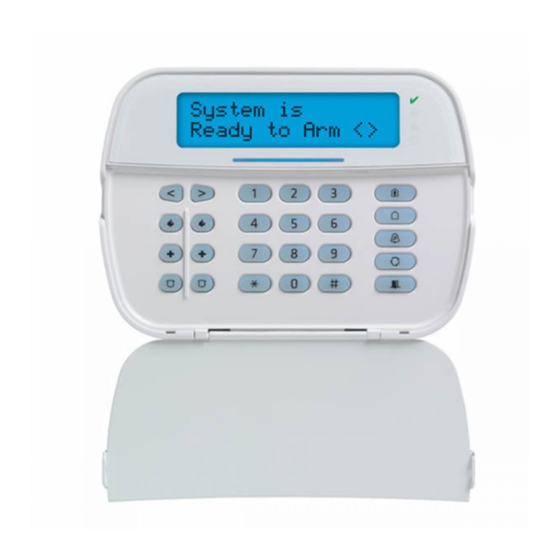
Chapter 2 2.0 Understanding Your Keypad The PowerSeries Neo Alarm System supports a variety of wireless, hardwired and proximity sensor LCD, LED and Icon keypads. All keypads come equipped with the LED status lights described in section 1 "Quick Reference". HS2LCD series keypads display system messages on their LCD screen. - Page 6 Chapter 2 HS2ICN Icon keypad Icon keypad with Prox. Tag support HS2ICNP HS2LED LED keypad HS2LCDRFx Alphanumeric LCD keypad with wireless receiver HS2LCDRFPx Alphanumeric LCD keypad with wireless receiver and Prox. tag support HS2ICNRFx Icon keypad with wireless receiver HS2ICNRFPx Icon keypad with wireless receiver and Prox.
-
Page 7: Securing The Premises
Chapter 3 3.0 Securing the Premises The PowerSeries Neo provides multiple setting modes as described below: Use when no one in your household will be home. Away mode activates all perimeter and interior sensors Away mode in the alarm system. Stay mode Use this mode when you are staying home, but expect someone to use the entrance door later. -
Page 8: Night Setting The System With The Keypad
Chapter 3 After successfully initiating the setting sequence the: Exit Delay in Progress indicator turns on. Ready indicator remains lit. Exit Delay timer begins counting down. Keypad beeps six times, continues beeping once per second until beeping rapidly in the final ten seconds. The system may be configured to have a persistent exit delay that only ends when the exit door is opened and closed, or when a button is pressed outside the pro- tected premises. -
Page 9: Silent Exit Delay
Chapter 3 Check that the Ready indicator is on and your system is ready to be set. Date Time JAN 02/13 2:06a Press [*][9] and, if required, enter your [access code]. Present Tag or Enter Code If zones have been bypassed, ICN or LED keypads bypass LED will light and the * Warning * bypassed zones #s will be shown. -
Page 10: Setting The System With A 2-Way Wireless Key
Chapter 3 To Quick Exit LCD Display Quick Exit in When the system is already set and the Set light is lit, press and hold the Quick Progress Exit key for 2 seconds press [*][0]. Exit the premises before the exit delay timer expires. After exiting, the delay timer will be canceled. - Page 11 Chapter 3 Press [*] to enter the function menu. Press (*) for <> Zone Bypass Press [*] or [1]. If required enter your [access code] or present your proximity tag. Zone Bypass <> (*) To Bypass Directly bypass zones by entering their [3 digit zone #]. If using an LCD keypad Zone 1 <>...
-
Page 12: Bypass Groups
Chapter 3 Press [0][0][0] Press (*) for <> Clear Bypasses then Bypass Cleared Scroll to Clear Bypasses using the keys and press [*]. All Bypassed zones Zones Unbypassed will now be open. To exit bypassing mode press [*]. 3.9 Bypass Groups Program frequently bypassed zones into the system as a bypass group. -
Page 13: Audible Exit Faults
To enable a 6-hour downloading window from any system keypad, enter [*] [6] [Master code] [5]. During this time, the panel will answer incoming downloading calls. DLS-3 downloading software allows you to program and control supported DSC security sys- tems from any PC-compatible computer. DLS-3 can send data and programming information to, and retrieve it from security sys- tems using a modem, or using the DSC PC- LINK device. - Page 14 Chapter 3 DLS- 3 allows for the ability to upload status reports from control panels, as well as print and view reports about the security sys- tem. Additionally, DLS- 3 can execute batch files to perform preprogrammed functions on a security system. - 14 -...
-
Page 15: The Powerseries Neo Security System
Chapter 4 4.0 The PowerSeries Neo Security System Your PowerSeries Neo has been designed to provide you with the greatest possible flexibility and convenience. Read this manual carefully and have your installer instruct you on how to operate your system and which features have been implemented in your sys- tem. - Page 16 Chapter 4 Use the system test described in “Testing Your System” to check the battery condition. We recommend, however, that the standby batteries be replaced every 3-5 years. For other system devices such as smoke detectors, passive infrared, ultrasonic or microwave motion detectors or glass- break detectors, consult the manufacturer’s literature for testing and maintenance instructions.
-
Page 17: Emergency Keys
Chapter 5 5.0 Emergency Keys IMPORTANT: EMERGENCY USE ONLY! Pressing both the emergency keys generates a Fire, Medical, or Panic Alarm, and alerts the monitoring station. e.g., to generate a medical alarm press both of the medical alarm keys for 2 seconds and the display on an LCD keypad will show Hold down keys for Med. -
Page 18: Viewing Alarms In Memory
Chapter 5 5.1.5 Viewing Alarms in Memory When an alarm occurs the keypad indicator illuminates. Viewing the Alarm memory provides more information on the sensor(s) that were tripped. When using a ICN or LED keypad the Memory LED will be lit and the zone numbers will be displayed. To View Alarms in Memory LCD Display Press [*][3]... -
Page 19: Wireless Keys And Other Devices
Chapter 6 6.0 Wireless Keys and other Devices In addition to the keypad, the PowerSeries Neo system can be controlled using a variety of devices: 2-way wireless keys Proximity Tags via SMS using a cellphone 6.1 Using 2-way Wireless Keys Note: Panic feature has not been evaluated by UL. -
Page 20: Sending Sms Commands To Your System
Chapter 6 To find the System’s Phone Number LCD Display Check that the Ready indicator is on and the system is unset. Date Time JAN 02/13 2:06a Press [*][6] Press (*) for <> User Functions press [*]and use the scroll keys to navigate to User Functions press [*] and enter [Master Code]. -
Page 21: Sms Responses From Your System
Chapter 6 6.3.4 SMS Responses from your System SMS responses are sent to the phone that initiated the command. System Response Notes Successful Sent when a command and control function is successfully performed by the panel. Unsuccessful Sent when a command and control function not successfully performed by the panel. Sent when a command sent was not accepted as valid by the system. -
Page 22: Managing Users
Chapter 7 7.0 Managing Users Different user access codes can be programmed in the PowerSeries Neo. The maximum number of user access codes are as fol- lows: 48 for HS2016/HS2016-4 72 for HS2032 95 for HS2064/HS2128 500 for HS2064 E 1000 for HS2128 E Each user access code can be: Uniquely labeled. -
Page 23: Adding, Changing And Deleting Access Codes
Chapter 7 To Open the Access Codes Menu LCD Display Press [*][5] Press (*) for <> Access Codes press [*] and use the scroll keys to navigate to Access Codes and press [*]. Enter [Master or supervisor code]. Present Tag or Enter Code Enter [User #] Press (*) for <>... -
Page 24: Naming A User
Chapter 7 If a tag is enrolled for this user you will be asked if you would like to delete the Tag. * To Delete Tag Press [*] to delete the tag. Press # to Exit Tag Deleted Successfully 7.1.3 Naming a User Adding or editing labels are accomplished by using the keypad to input the desired letters or numbers. - Page 25 Chapter 7 Use the keys to cycle through the User Options and press to toggle configuring the dis- (*) To Toggle <> played option. Bell Squawk Y If using an LED or ICN keypad press the [feature number as listed above]. - 25 -...
-
Page 26: User Functions
Chapter 8 8.0 User Functions The PowerSeries Neo allows for a variety of user configurable functions as listed below: Event Buffer Auto Set Time Late To Open Contrast Control ... -
Page 27: Allowing The Installer To Service Your System Remotely - Dls
Chapter 8 Press [*]to open a days of the week sub menu. Scroll the days of the week and press Press (*) for <> [*] to set the time for that day. Sunday If using an ICN or LED keypad to select the desired day press [1-7] where 1= Sunday and 7=Saturday. -
Page 28: Changing The Brightness Of The Lcd Keypad
Chapter 8 Press [*] to open a days of the week sub menu. Scroll the days of the week and press Press (*) for <> [*] to set the time for that day. Sunday If using an ICN or LED keypad to select the desired day press [1-7] where 1= Sunday and 7=Saturday. -
Page 29: Resetting The System
Chapter 8 Press [#] to return to the Ready state. 8.13 Resetting the System 8.13.1 Engineer's Reset If an alarm has occurred on your system, the system will not allow you to reset (Ready light is OFF). You will need to contact your installer. -
Page 30: Trouble Conditions
Chapter 8 8.15 Trouble Conditions Occasionally, you may have a problem with your Alarm Controller or telephone line. If this happens, your Alarm Controller iden- tifies the problem and displays an error message. Refer to the provided list when you see an error message on the display. If addi- tional help is required, contact your distributor for service. - Page 31 Chapter 8 Trouble Trouble Trouble Trouble Trouble Description Notification Condition Types Level 2 Level 1 Level 3 AC Troubles The system is experiencing loss of power. Call for service. Zone Zone label or If the building and/or neighborhood has lost electrical 001-128 power, the system will continue to operate on battery for Siren...
- Page 32 Chapter 8 Trouble Trouble Trouble Trouble Trouble Description Notification Condition Types Level 2 Level 1 Level 3 Module Super- The system has detected a supervisory trouble condition HSM2HOST vision with one or more modules on the system. Call for service. Keypad Keypad 1-16 Zone...
-
Page 33: Managing Partitions
Chapter 9 9.0 Managing Partitions A partition is a limited area of the premises which operates independently from the other areas. Partitioning a system can be bene- ficial if the property has outbuildings that need to be secured independently of a main area or if the home has a separate apartment. Each partition can have its own keypad, or a keypad can have access to all partitions. -
Page 34: Additional Features
Chapter 10 10.0 Additional Features 10.1 Turning the Chime ON/OFF Turning the chime on audibly notifies you whenever an entry/exit sensor is tripped. To turn the Chime ON or OFF LCD Display Press to toggle the Chime ON or OFF for the current partition. An access code Door Chime may be required to change this setting. -
Page 35: Swinger Shutdown
Chapter 10 10.6 Swinger Shutdown The Control Panel has a swinger shutdown feature that when enabled a programmable number of trips shall shut down the zone. Note: Must be enabled and configured by installer. 10.7 Call Waiting The Control Panel includes a programmable option for call waiting to prevent a call waiting line from interfering with the alarm verification process. -
Page 36: Regulatory Agency Statements
-A (use of two warning devices and internal dialer required -B (self-powered warning device and internal dialer required -C (use of DSC compatible alternate communicator in back-up or redundant mode) -D (use of DSC compatible alternate communicator with encryption enabled required.) Note: For EN50131 complian installations only the intrusion portion of the alarm system has been investigated. -
Page 37: Installer Warning
Chapter 12 12.0 Installer Warning Warning Please Read Carefully Note To Installers: This warning contains vital information. As the only individual in contact with system users, it is your responsibility to bring each item in this warning to the attention of the users of this system. System Failures This system has been carefully designed to be as effective as possible. -
Page 38: Safety Instructions
Chapter 13 13.0 Safety Instructions This equipment is stationary-fixed and must be installed by Service Persons only (Service Person is defined as a person having the appropriate technical training and experience necessary to be aware of hazards to which that person may be exposed in performing a task and of measures to minimize the risks to that person or other persons). -
Page 39: Eula
EULA, even if this EULA is deemed to be a modification of any previous arrangement or contract. If You do not agree to the terms of this EULA, DSC is unwilling to license the SOFTWARE PRODUCT to You, and You have no right to use it. - Page 40 CLAIMS OF THIRD PARTIES, INCLUDING CUSTOMERS, AND INJURY TO PROPERTY. WARNING: DSC recommends that the entire system be completely tested on a regular basis. However, despite frequent testing, and due to, but not limited to, criminal tampering or electrical disruption, it is possible for this SOFTWARE PRODUCT to fail to perform as expected.
-
Page 41: Locating Detectors And Escape Plan
Chapter 15 15.0 Locating Detectors and Escape Plan The following information is for general guidance only and it is recommended that local fire codes and regulations be consulted when locating and installing smoke and CO alarms. 15.1 Smoke Detectors Research has shown that all hostile fires in homes generate smoke to a greater or lesser extent. Experiments with typical fires in homes indicate that detectable quantities of smoke precede detectable levels of heat in most cases. -
Page 42: Carbon Monoxide Detectors
Chapter 15 Consider the following when making your escape plans: Make sure that all border doors and windows are easily opened. Ensure that they are not painted shut, and that their lock- ing mechanisms operate smoothly. If opening or using the exit is too difficult for children, the elderly or handicapped, plans for rescue should be developed. This includes making sure that those who are to perform the rescue can promptly hear the fire warning signal. -
Page 43: Reference Sheets
Chapter 16 16.0 Reference Sheets Fill out the following information for future reference and store this guide in a safe place. 16.1 System Information Mark if Buttons are Enabled [F] FIRE [M] Medical [P] PANIC The Exit Delay Time is _______ seconds. The Entry Delay Time is _______ seconds. -
Page 44: Access Code And Sensor/Zone Information
Chapter 16 16.3 Access Code and Sensor/Zone information Master Code [01] : _________________________ Access Code Reference Sheet Code Access Code Code Access Code Code Access Code Code Access Code ... - Page 45 Chapter 16 Sensor/Zone Information Sensor Protected Area Sensor Type Sensor Protected Area Sensor Type ...
- Page 46 Chapter 16 Sensor Protected Area Sensor Type Sensor Protected Area Sensor Type ...
- Page 47 © 2016 Tyco Security Products. All Rights Reserved. • www.dsc.com The trademarks, logos, and service marks displayed on this document are registered in the United States [or other countries]. Any misuse of the trademarks is strictly pro- hibited and Tyco Security Products will aggressively enforce its intellectual property rights to the fullest extent of the law, including pursuit of criminal prosecution wherever necessary.
Need help?
Do you have a question about the Neo Power HS2016 and is the answer not in the manual?
Questions and answers