Advertisement
EX17908 Web-Smart Switch Installation Guide
1
Unpacking
Unpack the items. Your package should include:
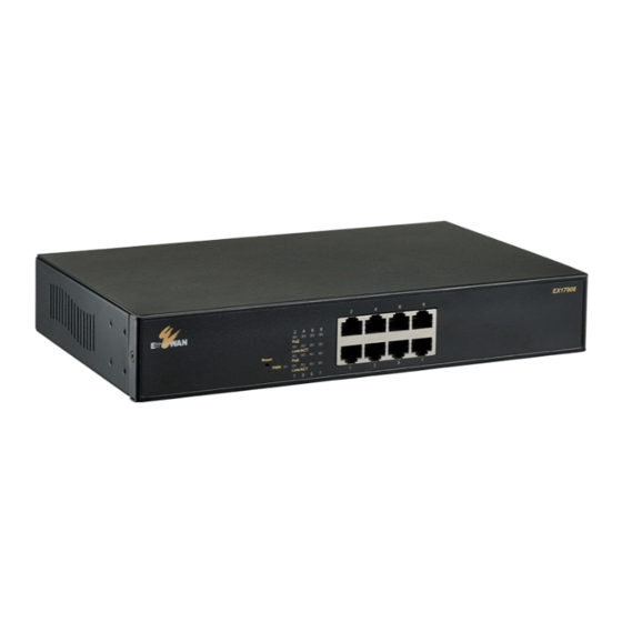
One EX17908 Web-Smart switch
One external power adapter
One CD containing this user's guide
If items are missing or damaged, notify your
EtherWAN representative. Keep the carton and
packing material.
2
What Else You Need
Category 5 or better Ethernet cables
Notebook PC with Ethernet (RJ-45) Interface
and installed Web browser
3
Select a Location
Desktop installations: Mount on a flat table
or shelf surface.
Rack installations: Use a 19-inch (48.3-
centimeter) EIA standard equipment rack
that is grounded and physically secure.
Identify a power source within 6 feet (1.8
meters).
Choose a dry area with ambient temperature
between 0 and 40ºC (32 and 104ºF).
Do not cover fans on the rear and side.
Keep away from heat sources, sunlight, warm
air exhausts, hot-air vents, and heaters.
Be sure there is adequate airflow.
EX17908
02/25/2020
Keep the switch at least 6 ft (1.83 m) away
from the nearest source of electromagnetic
noise, such as a photocopy machine.
4
Connect to the Data Ports
The switch provides eight 10/100/1000 Mbps RJ-
45 ports that can connect to Power over
Ethernet (PoE) devices, such as an IP surveillance
camera or a Voice Over Internet Protocol (VoIP)
phone.
Insert one end of a Category 5 or better
A.
Ethernet cable into a switch port.
Connect the other end into the Ethernet port
B.
of the device.
Repeat steps A and B for each additional
C.
device you want to connect to the switch.
5
Apply AC Power
Connect the female end of the supplied AC
A.
power adapter cable to the power receptacle
on the switch rear panel. Connect the other
end to a grounded 3-pronged AC outlet.
On the switch rear panel, move the ON/OFF
B.
switch to the ON position.
When you apply AC power:
All green
PoE
and
Link/ACT
LEDs blink
momentarily.
Copyright 2020 EtherWAN Systems, Inc.
All Rights Reserved
The fans start.
The yellow
Power
LED goes ON.
The
Link/ACT
LEDs for every port connected
to a device flash, as the switch conducts a
brief Power On Self-Test (POST).
6
Configure the Switch
After the switch passes its POST, perform a basic
configuration of the switch.
Connect an available 10/100/1000 Mbps RJ-
A.
45 switch port to a PC using a Category 5 or
better Ethernet cable.
Confirm that the
Link/ACT
LED for the switch
B.
port to which the PC is connected is ON.
Configure the PC's TCP/IP settings to use the
C.
subnet 192.168.2.2.
In a Web browser, type
http://192.168.2.1
D.
in the address bar and press Enter.
At the Password screen, type
admin
E.
default password, and then click
Continued on next page
as the
Apply
.
Page 1
W70G-E17908XQ2
Advertisement
Table of Contents

Related Manuals for EtherWAN EX17908


Summary of Contents for EtherWAN EX17908
- Page 1 EX17908 Web-Smart Switch Installation Guide Keep the switch at least 6 ft (1.83 m) away The fans start. Unpacking from the nearest source of electromagnetic The yellow Power LED goes ON. Unpack the items. Your package should include: noise, such as a photocopy machine.
- Page 2 EX17908 Web-Smart Switch Installation Guide At the Web management interface, click Click Apply Front Panel LEDs Configuration > System Username and password are case-sensitive. Color Status Permitted characters are a-z, A-Z, 0-9, Power Yellow ON = switch is receiving power.
Need help?
Do you have a question about the EX17908 and is the answer not in the manual?
Questions and answers