
Subscribe to Our Youtube Channel
Related Manuals for EtherWAN EX17908 Series


Summary of Contents for EtherWAN EX17908 Series
- Page 1 EX17908 Web-Smart Switch FastFind Links Introduction User’s Guide Unpacking and Installation Preparing to Configure the Switch Configuring the Switch...
- Page 2 Disclaimer of Liability The information contained in this document is subject to change without notice. EtherWAN is not liable for any errors or omissions contained herein or for resulting damage in connection with the information provided in this manual.
-
Page 3: Preface
Preface Audience This guide is designed for the person who installs, configures, deploys, and maintains the Ethernet network. This document assumes the reader has moderate hardware, computer, and Internet skills. Document Revision Level This section provides a history of the revision changes to this document. Revision Document Version Date... -
Page 4: Document Conventions
Document Conventions This guide uses the following conventions to draw your attention to certain information. Safety and Warnings This guide uses the following symbols to draw your attention to certain information. Symbol Meaning Description Note Notes emphasize or supplement important points of the main text. Tips provide helpful information, guidelines, or suggestions for performing tasks more effectively. -
Page 5: Table Of Contents
Contents Preface ........................iii Changes in this Revision ............錯誤! 尚未定義書籤。 Document Conventions .................... iv Safety and Warnings ..................iv Typographic Conventions ................... iv Contents ........................v 1 Introduction ......................7 Key Features ......................8 Quick Start Guide ...................... 9 2 Unpacking and Installation ................ - Page 6 Disabling Proxy Settings ..................22 Disabling Proxy Settings in Internet Explorer ............. 22 Disabling Proxy Settings in Firefox ..............23 Disabling Proxy Settings in Safari ..............23 Disabling Firewall and Security Software ..............24 4 Configuring the Switch ..................25 Logging in to the Web Management Interface ............
-
Page 7: Introduction
1 Introduction Topics: Congratulations on your purchase of the EX17908 Web-Smart Switch from EtherWAN Systems, Inc. Your EtherWAN switch is a Key Features (page 8) © state-of-the-art IEEE-compliant network solution designed for Quick Start Guide (page 9) © users who require high-performance along with the power of management to eliminate bottlenecks and increase productivity. -
Page 8: Key Features
Key Features This section summarizes the key features of the EX17908 switch. 8 10/100/1000BASE-TX ports supporting IEEE 802.3at Power over Ethernet (PoE) Power Sourcing Ÿ Equipment (PSE) PoE power budget up to 30 W/port, with a total power budget of 240 Watts Ÿ... -
Page 9: Quick Start Guide
Quick Start Guide The following procedure enables advanced users to get their switch up and running in the shortest possible time. For detailed installation instructions, refer to the sections in the right column below. Step Description For Reference, See… Find a Location for the Switch “Preparing the Site”... -
Page 10: Unpacking And Installation
2 Unpacking and Installation Topics: This chapter describes how to unpack and install the EX17908 switch. Unpacking the Hardware © (page 11) System Requirements © (page 11) Hardware Features (page © Installing the Switch (page © Where to Go from Here ©... -
Page 11: Unpacking The Hardware
One CD containing this user’s guide Ÿ If any item is damaged or missing, notify your authorized EtherWAN representative. Keep the carton, including the original packing material, in case you need to store the product or return it. System Requirements... -
Page 12: Hardware Features
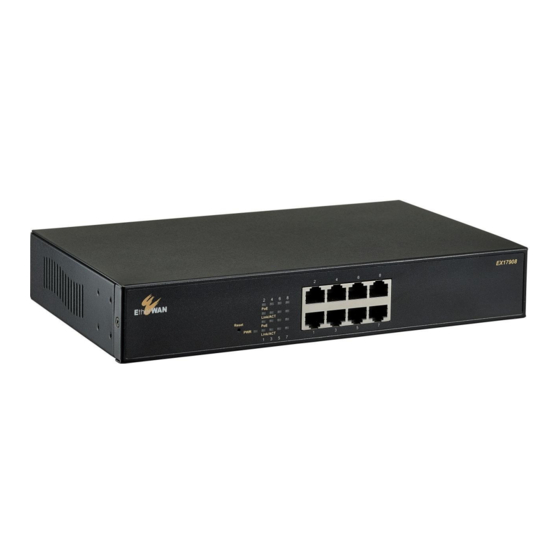
Hardware Features The following sections describe the hardware features of the EX17908 switch. Front Panel Figure 2-1 shows the front panels of the EX17908 switch. Reset 10/100 /1000 Button Mbps Ports Status LEDs Figure 2-1. Front Panel of the EX17908 Switch 10/100/1000 Mbps RJ-45 Ports The EX17008 switch has 8 10/100/1000 Mbps RJ-45 ports designated 1 through 8 (see Figure 2-1). -
Page 13: Rear Panel
1. Leave power cord connected to the switch. 2. Using a pin or paper clip, press and hold the reset button for about 10 seconds, then release the reset button. 3. Wait for the switch to reboot. Note: You can perform a “warm” restart that reboots the switch and keeps all overrides made to the switch’s default settings using the Warm Restart page in the switch’s Web management interface (see “Warm Restart Page”... -
Page 14: Side And Bottom Panels
ON/OFF Switch Power Receptacle Figure 2-2. Rear Panel of the EX17908 Switch Side and Bottom Panels The EX17908 side panels have vents for cooling. Be sure these vents are not blocked. The bottom panel has a product label that shows regulatory compliance, product serial number, and other information. -
Page 15: Preparing The Site
Preparing the Site Before you install your switch, be sure your operating environment meets the operating environment requirements in Table 2-2. Table 2-2. Site Requirements Characteristics Requirements Mounting Desktop installations: Provide a flat table or shelf surface. Rack-mount installations: Use a 19-inch (48.3-centimeter) EIA standard equipment rack that is grounded and physically secure. Access Locate the switch in a position that lets you access the front panel RJ-45 ports, view the front panel LEDs, and access the rear-panel power connector. -
Page 16: Connecting To The 10/100/1000 Mbps Rj-45 Ports
Figure 2-3. EX17908 Switch Dimensions Connecting to the 10/100/1000 Mbps RJ-45 Ports The front panel of the switch provides 8 10/100/1000 Mbps RJ-45 ports (see “10/100/1000 Mbps RJ-45 Ports” on page 12). To prevent ESD damage, follow normal board and component handling procedures. -
Page 17: Checking The Installation
Checking the Installation Before you apply power: Inspect the equipment thoroughly. Ÿ Verify that all cables are installed correctly. Ÿ Check cable routing to make sure cables are not damaged or create a safety hazard. Ÿ Be sure all equipment is mounted properly and securely. Ÿ... -
Page 18: Where To Go From Here
Where to Go from Here After you power-up the switch for the first time, you configure it using the switch’s built-in management software. For more information, see Chapters 3 and 4. EX17908 Web-Smart Switch User Guide... -
Page 19: Preparing To Configure The Switch
3 Preparing to Configure the Switch Topics: After you install the switch, configure it using the switch’s built-in Web management interface and a Web browser on a PC. Connecting the PC (page © For the Web browser to access the switch’s Web management interface, the PC and switch must be on the same subnet. -
Page 20: Connecting The Pc
Connecting the PC To connect a PC to the switch: 1. Insert one end of a Category 5 or better Ethernet cable into an available 10/100 Mbps RJ-45 port on the front panel of the switch. 2. Connect the other end of the cable to the Ethernet port on the PC you will use to configure the switch. - Page 21 4. Click Internet Protocol Version 4 (TCP/IPv4), and then click Properties. 5. In the General tab, click Use the following IP address. 6. In the IP address field, type 192.168.2.10. Tip: Although the last digit in the previous step is 10, in reality, this digit can be any number between 0 and 255, except the number 1 because the address 192.168.2.1 is already being used by the switch.
-
Page 22: Disabling Proxy Settings
8. Click OK to exit the current dialog box, and then click OK again to exit the initial dialog box. Disabling Proxy Settings Before using the switch’s Web management interface, disable proxy settings in your Web browser. Otherwise, you might not be able to view the switch’s Web-based configuration pages. Disabling Proxy Settings in Internet Explorer The following procedure describes how to disable proxy settings in Internet Explorer 5 and later. -
Page 23: Disabling Proxy Settings In Firefox
8. For the option Check for newer versions of stored pages, select Every time I visit the webpage. 9. Click OK until you close all open browser dialog boxes. Disabling Proxy Settings in Firefox The following procedure describes how to disable proxy settings in Firefox. Start Firefox. -
Page 24: Disabling Firewall And Security Software
Disabling Firewall and Security Software If you encounter problems connecting to the switch, disable any firewall or security software that may be running on your PC before configuring the switch. For more information, refer to the documentation for your firewall. EX17908 Web-Smart Switch User Guide... -
Page 25: Configuring The Switch
4 Configuring the Switch Topics: After you attach a PC to the switch and configure the PC to the same subnet as the switch, use the information in this Logging in to the Web © chapter to configure the switch. Management Interface (page 26) Inactivity Timeout (page... -
Page 26: Logging In To The Web Management Interface
Logging in to the Web Management Interface To access the switch’s configuration settings, launch a Web browser on the PC you configured in Chapter 3 and log in to the switch’s Web management interface. Launch a Web browser. Note: Your computer does not have to be online to configure your switch. 2. -
Page 27: Inactivity Timeout
Note: First-time logins must set the switch’s DHCP setting (see page 33), default username, and default password (see page 30). Inactivity Timeout For security, the switch has an inactivity timeout feature that closes the current Web management session automatically if the interface is not used for 60 seconds. This feature prevents a session from remaining open to unauthorized users if the operator should walk away from the management PC. -
Page 28: Web Management Interface Menus
Web Management Interface Menus Table 4-1 describes the pages in the Web management interface. The first time you configure the switch, you must configure the following settings on the Configuration > System page: DHCP Enabled to specify whether the switch will receive an IP address allocated Ÿ... -
Page 29: Configuration Menu
Configuration Menu The Configuration menu lets you perform the following tasks: System ¾ changes the system configuration Ÿ settings, including the DHCP setting, and the default username and password used to log in to the Web management interface. See page 30. Ports ¾... - Page 30 System Configuration Page Path: Configuration > System The System Configuration page is organized into two areas: The top area contains read-only fields that show the switch’s current configuration Ÿ settings. The bottom area lets you change the switch’s configuration settings. Ÿ...
- Page 31 The first time you log in, we recommend you: Confirm the DHCP setting Ÿ Change the default username and password used to log in to the switch’s Web Ÿ management interface to prevent unauthorized individuals from gaining access to the switch.
- Page 32 Field Description Default Password Case-sensitive password used to log in to the Web management interface admin Inactivity Timeout Number of minutes a Web management session can be idle before the switch ends the session. Range: 60 – 10000 seconds. SNMP enabled Enables or disables the switch’s Simple Network Management Protocol (SNMP) Checked capabilities.
- Page 33 Port Configuration Page Path: Configuration > Ports The Port Configuration page lets you enable jumbo frames, configure power saving mode, and view the switch port status and configure port modes. EX17908 Web-Smart Switch User Guide...
- Page 34 Jumbo Frames The switch provides efficient large sequential data transfers by supporting jumbo frames up to 9000 bytes. Compared to standard Ethernet frames that run up to 1500 bytes, using jumbo frames significantly reduces the per-packet overhead required to process protocol encapsulation fields, reduce processing time, and increase transfer performance.
- Page 35 Port Settings The port settings appear in the center of the Port Configuration page. Each row of the page corresponds to one port. The following table describes the port settings. Field Description Port Number corresponding to each port on the switch. Link Read-only fields that show whether the switch ports are up or down.
- Page 36 Drop Frames After Excessive Collisions When the Drop frames after excessive collisions check box is checked, the switch drops frames after an excessive number of collisions. By default, this check box is checked. Apply and Refresh Buttons If you change any settings on the Port Configuration page, click Apply to apply the changes. Clicking the Refresh button updates the screen with the latest status.
- Page 37 Port Segmentation (VLAN) Configuration Path: Configuration > VLANs The switch supports up to 16 VLANs based on the 802.1Q standard. From the Port Segmentation (VLAN) Configuration page, you can create and delete VLANs, and change the VLAN port membership. The Add a VLAN area lets you add a VLAN. The VLAN Configuration List shows the VLANs that have been configured.
- Page 38 3. By default, all switch ports are members of the VLAN. To exclude a port from this VLAN, uncheck the Member check box for the port. 4. Click Apply. The Port Segmentation (VLAN) Configuration page reappears, with the VLAN you configured shows below VLAN Configuration List. 5.
- Page 39 Modifying a VLAN There may be times when you need to modify the port membership in a VLAN. To modify a VLAN: 1. Under VLAN Configuration List, click the ID of the VLAN you want to edit. 2. Click Modify. The VLAN Setup page appears, with the settings for the VLAN you selected. 3.
- Page 40 2. Complete the settings in the page, and then click Apply. Field Description Port Number corresponding to each port on the switch. VLAN aware Enabled Enables or disables VLAN awareness for each port. Checked = makes the port VLAN-aware. VLAN aware ports use VLAN-tagged frames to determine the ·...
- Page 41 Field Description Pvid The PVID (Port VLAN ID) is associated with untagged, ingress packets and assigned to untagged frames received on the specified interface. The PVID has no effect on ports whose Packet Type is set to “Tagged Only.” You cannot remove a port from VLAN 1, unless its PVID is changed to a value other than 1. Outgoing packets are tagged unless the packet’s VLAN ID is the same as the PVID.
- Page 42 Aggregation/Trunking Page Path: Configuration > Aggregation The Aggregation/Trunking Configuration page lets you bundle (or aggregate”) multiple links together to act as a single physical link for increased throughput. Bundling links provides load balancing and redundancy of links in a switched inter-network. In reality, the link does not have an inherent total bandwidth equal to the sum of its component physical links.
- Page 43 RSTP System Configuration Page Path: Configuration > RSTP For optimal performance, there should be a single active path between two networking devices in an Ethernet network. Rapid Spanning Tree Protocol (RSTP) provides redundant paths and prevents network loops that can create excessive traffic and slow down performance.
- Page 44 RSTP System Configuration Field Description Default System Priority Identifies the root bridge. The bridge with the lowest value has the highest priority and is selected as 32768 the root. If the value has been changed, user has to reboot the switch. The value must be multiple of 4096 according to the protocol standard rule Hello Time Interval, in seconds, that determines how often the switch broadcasts hello messages to other...
- Page 45 IGMP Configuration Page Path: Configuration > IGMP The IGMP Configuration page lets you configure the switch’s Internet Group Management Protocol (IGMP) settings. IGMP allows the switch to “listen in” on IGMP conversations between hosts and routers by processing Layer 3 IGMP packets sent in a multicast network. When IGMP is enabled, the switch analyzes all IGMP packets between hosts connected to the switch and multicast routers in the network.
- Page 46 Field Description Default IGMP Querying Enables or disables IGMP querying. Checked Enabled Checked = port can serve as the Querier, which is responsible for asking hosts if they want to · receive multicast traffic. Unchecked = port cannot serve as the Querier. ·...
- Page 47 Mirroring Configuration Page Path: Configuration > Mirroring The Mirroring Configuration page lets you configure the switch’s port mirroring settings. Port mirroring is used on a network switch to send a copy of network packets seen on one switch port (or an entire VLAN) to a network monitoring connection on another switch port. This feature is commonly used for network appliances that require monitoring of network traffic, such as an intrusion-detection system.
- Page 48 QoS Configuration Page Path: Configuration > Quality of Service The QoS Configuration page lets you configure the switch to deliver better resource reservation control. If you change the settings on this page, click Apply to apply your settings. A Refresh button lets you update the information on the screen.
- Page 49 Figure 4-3. QoS Configuration Page when QoS Mode is Set to 802.1p Figure 4-4. QoS Configuration Page when QoS Mode is Set to DSCP EX17908 Web-Smart Switch User Guide...
- Page 50 PoE (Power over Ethernet) Configuration Page Path: Configuration > Power over Ethernet Power over Ethernet (PoE) is a mechanism for supplying power to network devices over the same cabling used to carry network traffic. PoE allows devices that require power, called Powered Devices (PDs), to receive power and data over existing infrastructure without having to upgrade the infrastructure.
- Page 51 Storm Control Configuration Page Path: Configuration > Storm Control Broadcast storms can occur when a device on your network malfunctions, or if application programs are not well designed or properly configured. If there is too much broadcast traffic on your network, performance can be degraded severely or all traffic can come to complete halt.
- Page 52 EX17908 Web-Smart Switch User Guide...
-
Page 53: Monitoring Menu
Monitoring Menu The Monitoring menu lets you perform the following tasks: Statistics Overview ¾ provides a statistical overview of Ÿ each switch port. See page 54. Detailed Statistics ¾ copies network traffic from one Ÿ port to another port. See page 55. RSTP Status ¾... - Page 54 Statistics Overview Page Path: Monitoring > Statistics Overview The Statistics Overview page is a read-only page that shows the following information for each switch port: Transmitted bytes Ÿ Transmitted frames Ÿ Received bytes Ÿ Received frames Ÿ Transmit errors Ÿ Receive errors Ÿ...
- Page 55 Detailed Statistics Page Path: Monitoring > Detailed Statistics The Detailed Statistics page is a read-only page that shows detailed port information arranged in the following categories: Receive total Ÿ Receive size counters Ÿ Receive error counters Ÿ Transmit total Ÿ Transmit size counters Ÿ...
- Page 56 RSTP VLAN Bridge Overview Page Path: Monitoring > RSTP Status The RSTP VLAN Bridge Overview page is a read-only page that shows the switch’s Rapid Spanning Tree Protocol information. Field Description VLAN Id VLAN identifier. Bridge Id Unique identifier for the switch in the Spanning Tree. Hello Time Time interval, in seconds, at which the root device transmits a configuration message.
- Page 57 IGMP Status Page Path: Monitoring > IGMP Status The IGMP Status page is a read-only page that shows the switch’s IGMP snooping statistics. Field Description VLAN ID VLAN identifier. Querier Shows whether Querying is enabled. Queries transmitted Number of transmitted Query packets. Queries received Number of received Query packets.
- Page 58 Ping Parameters Page Path: Monitoring > Ping The Ping Parameters page lets you check connectivity between the switch and devices on the network. To perform a ping: 1. In the Target IP address field, enter the IP address you want the switch to contact. 2.
-
Page 59: Maintenance Menu
Maintenance Menu The Maintenance menu lets you perform the following tasks: Warm Restart ¾ restarts the switch. See page 60. Ÿ Factory Default ¾ returns the switch to factory default Ÿ settings. See page 61. Software Upload ¾ updates switch firmware. See page 62. Ÿ... - Page 60 Warm Restart Page Path: Maintenance > Warm Restart The Warm Restart page lets you restart the switch. Any changes you made to the switch’s factory default configuration are maintained after the warm start. EX17908 Web-Smart Switch User Guide...
- Page 61 Factory Default Page Path: Maintenance > Factory Default The Factory Default page lets you restart the switch and return it to its factory default settings. Any changes you made to the switch’s factory default configuration will be discarded after the reboot.
- Page 62 Software Upload Page Path: Maintenance > Software Upload The Software Upload page lets you upgrade the switch firmware. 1. Download the switch firmware. 2. At the Software Upload page, click the Browse button. 3. In the Choose File to Upload dialog box, go to the location where the firmware file is located, and then click the file and click Open.
- Page 63 Configuration Upload Page Path: Maintenance > Configuration File Transfer The Configuration Upload page lets you lets you save the switch configuration on your computer or restore the switch configuration by uploading a configuration file that you saved previously on your computer. To save the switch configuration: 1.
- Page 64 To recover switch settings using a configuration file you saved using the procedure above: 1. Under Configuration Upload, click Browse. 2. When the Choose File to Upload dialog box appears, use the dialog box to go to the location where the bin file resides, and then click the file and click Open. 3.
-
Page 65: Troubleshooting
5 Troubleshooting Topics: This chapter provides information about troubleshooting the switch. Troubleshooting Chart © (page 66) Additional © Troubleshooting Suggestions (page 67) EX17908 Web-Smart Switch User Guide... -
Page 66: Troubleshooting Chart
Troubleshooting Chart Table 5-1 symptoms, causes, and solutions of possible problems. Table 5-1. Troubleshooting Chart Symptom Cause Solution Power LED is OFF. The switch is not receiving Check the power cord connections for the switch at the switch and the power. -
Page 67: Additional Troubleshooting Suggestions
(see “Reset Button” on page 12) or use the Maintenance > Warm Restart page on the switch’s Web management interface (see “Warm Restart Page” on page 60). If the problem continues, contact EtherWAN Systems technical support. Auto-Negotiation The 10/100 Mbps ports negotiate the correct duplex mode and speed if the switch is configured for auto-negotiation (this is the switch’s default setting) and the device at the other... -
Page 68: Technology
Appendix A - Specifications Technology Specification Description Standards: IEEE802.3, 10BASE-T · IEEE802.3u, 100BASE-TX · IEEE802.3ab, 1000BASE-T · IEEE802.3x,full-duplex and flow control · IEEE802.3at, Power over Ethernet (PoE) · Forward and Filtering 10 Mbps: 14,880 pps · Rate: · 100 Mbps: 148,810 pps 1000 Mbps: 1,488,100 pps ·... -
Page 69: Mechanical
Mechanical Specification Description Casing: Metal case Dimensions: 266 mm (W) x 160 mm (D) x 44 mm (H) (10.47" (W) x 6.30" (D) x 1.73" (H)) Weight: 1.52 Kg (3.35 lbs) Installation: Desktop · Rack Mounting · Interface Specification Description Ethernet Ports: 10/100/1000BASE-T: 8 ports (PoE) LED Indicators:... -
Page 70: Index
Index Inactivity timeout, 27 Internet Group Management Protocol, 45, 47 Adding a VLAN, 37 Aggregation, 42 Auto-negotiation, 66 Jumbo frames, 30, 34 Backup, 62 Key features, 8 Broadcast storms, 51 Maintenance menu, 58 Configuration Menus download, 62 Configuration, 29 upload, 62 Maintenance, 58 Configuration menu, 29 Monitoring, 52... - Page 71 Quality of Service, 48 configuration, 62 firmware, 61 Username, 30 Rapid spanning tree protocol, 43 Recovery, 62 Reset button, 12 VLAN Restarting the switch adding, 37 reset button, 12 configuring ports, 39 Warm Restart page, 59 deleting, 39 modifying, 39 Spanning tree, 43 Specifications, 67 Web management interface, 27...
- Page 72 TEL: +886 -2- 6629-8986 Email: info@etherwan.com.tw EtherWAN has made a good faith effort to ensure the accuracy of the information in this document and disclaims the implied warranties of merchantability and fitness for a particular purpose, and makes no express warranties, except as may be stated in its written agreement with and for its customers.
Need help?
Do you have a question about the EX17908 Series and is the answer not in the manual?
Questions and answers