Table of Contents
Advertisement
Quick Links
Advertisement
Table of Contents

Related Manuals for Intellinet NSC10-WG 550918


Summary of Contents for Intellinet NSC10-WG 550918
- Page 1 NSC10-WG NetWork Camera uSer maNual MODEL 550918 INT-550918-UM-0709-01...
-
Page 2: Table Of Contents
table of CoNteNtS section page 1 INTRODUCTION ................3 System Requirements ............3 1.2 Package Contents ..............3 2 HARDWARE ................4 2.1 Controls & Indicators ............4 2.2 Installation ................5 3 SOFTWARE INSTALLATION ............5 3.1 Administrator Utility .............. 9 3.2 Viewer ................ -
Page 3: Introduction
1 iNtroduCtioN Thank you for purchasing the INTELLINET NETWORK SOLUTIONS ™ NSC10-WG Network Camera, Model 550918. Ideal camera for home-network-based video streaming, the NSC10-WG Network Camera can be conveniently accessed remotely over the Internet, allowing you to save snapshots or record directly from your Web browser to the local hard drive without installing any software or drivers. -
Page 4: Hardware
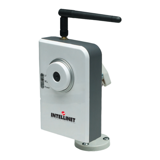
2 hardWare Antenna and reverse SMA connector 2.1 Controls & Indicators The focus ring allows you to adjust the focus of the camera simply by rotating the ring while viewing the live image. Focus ring 2.1.1 LEDs LAN LED WLAN LED The LEDs indicate the camera and network Power LED status. -
Page 5: Installation
2.2 Installation Once you’ve unpacked all the NSC10-WG Network Camera components and verified that all items are accounted for (see Package Contents, Page 3): • Connect the LAN port of the camera to your switch/router or other network device using the included network cable. • Connect the Power jack of the camera to an A/C outlet using the included power adapter and confirm that the Power LED is on. NOTE: It’s highly recommended that you use only the power adapter that comes with this camera. • Confirm that you have the correct VGA driver and DirectX 9.0 or above installed. 3 SoftWare iNStallatioN The Internet Camera Install Wizard utility on the included software CD will guide you through the installation process. - Page 6 3. The system will begin the installation procedure. When the second Welcome screen displays, click “Next” to continue the installation. 4. To install the software program in a different location, click “Change” on the Choose Destination Location screen. Otherwise, click “Next” to continue. SOFTWARE INSTALLATION...
- Page 7 5. With the Ready to Install the Program screen displayed, click “Install” to begin installation. 6. The automatic installation procedure presents a Setup Status screen to indicate progress. SOFTWARE INSTALLATION...
- Page 8 7. With the InstallShield Wizard Complete screen displayed, click “Finish” to complete the Administrator utility installation. 8. On the initial welcome screen of the wizard, click “Install 16 Chan(nel) Camera Viewer.’’ The Viewer installation will automatically begin, with steps similar to those of the Administration utility. SOFTWARE INSTALLATION...
-
Page 9: Administrator Utility
3.1 Administrator Utility The Administrator utility allows you to search for and set up cameras located within an intranet or on the Internet. Once installed, it displays all NSC10-WG Network Cameras it finds. Choose the one you want to configure and click on the Configure icon (circled below) to proceed. When prompted with the Login screen, enter the default password (“1234”) and click “OK” to log in to the IP setup (LAN Settings) screen. (Default username: admin.) The NSC10-WG Network Camera works through the network (TCP/IP Protocol), so the IP address and subnet SOFTWARE INSTALLATION... -
Page 10: Viewer
mask setting must be correct to access the camera. The wizard will detect the IP address status of your network automatically and suggest a free IP address for the camera (with “DHCP” selected by default). You can accept the suggested values or enter the values — detailed below in 4.1 LAN Settings — manually by selecting “Manual IP.” NOTE: Remember that the subnet mask must be the same for both the camera and PC. - Page 11 and “OK.” The Viewer will display the channel you’ve just configured. For complete configuration instructions, see Section 5: Viewer Operation. SOFTWARE INSTALLATION...
-
Page 12: Administrator Utility Operation
4 admiNiStrator utility operatioN Besides the auto install, there are two other ways to launch the Admin utility: • Go to Start on the desktop and click/select “Programs\ IP Camera\Admin Utility.” • Double-click the IP Cam Admin Utility icon on your desktop (shown at right). Once the utility is started, it will search for and list all the cameras in the network, with specific details and administrator options as shown and explained below (and briefly introduced in 3.1 Administrator Utility). -
Page 13: Lan Settings
4.1 LAN Settings As mentioned in 3.1 Administrator Utility, the default setting on this screen is “DHCP,” meaning that the entries below need to be made only when you select “Manual IP.” IP — Enter an unused IP address within the IP address range used on your LAN. For example, if the IP address of your LAN is in the range of 192.168.2.1 to 192.168.2.254, you can set an unused IP address from that range for the camera, such as 192.168.2.250. -
Page 14: Security
4.2 Security The Security screen lets you make the changes detailed below. Camera Name — The default is “IC1500WG.” It’s suggested that you enter a name for each camera that will provide immediate recognition of a camera’s purpose. New Password — If you’re changing the password for a camera, enter the new password in this field. -
Page 15: Viewer Operation
5 vieWer operatioN The Viewer can be activated by clicking its desktop/quick-launch icon or by selecting “IPCam Surveillance Software” from the Start menu’s Internet Camera folder. IMPORTANT: The Viewer software will only work with a monitor resolution setting of 1024 x 768. Be sure this is your setting before you use the Viewer; otherwise, it won’t start. video diSplay area diSplay... - Page 16 connected cameras. Click once to activate the function (the icon turns blue); click again to stop scanning (the icon turns white). NOTE: If a camera is configured but disconnected, it will still display in a scan sequence: The view will be blank and “Disconnected” will appear in the upper-left corner of the display. Zoom Out (3) — Click to view more of what’s available in the selected camera image. NOTE: This function is available only with cameras that feature it. Zoom In (4) — Click to view more details of the selected camera image. It may be necessary to first use the PTZ controls to identify and isolate the part of the image you want to zoom in on.
-
Page 17: Configuration
Playback (9) — Click to display the Playback screen so you can find the previously recorded video file you want to view. Two search options are presented: Time Search presents all video files created within a specified time period; Motion Search presents all video files created by the motion detection function within a specified time period. Enter/ select “From” and “To” values in the appropriate fields, then click the corresponding “Search” button. All found videos corresponding to those parameters will be displayed as a list in the window at the right. Highlight the file you want to view and click “Play.” Snapshot (10) — Click to take a snapshot of a selected camera image. Snapshots can be saved to a storage folder on your hard drive as explained in 5.2.2.1 General (Data Directory). Only the available space on your hard drive limits the number of snapshots that can be taken. -
Page 18: Configure Cameras
5.2.1 Configure Cameras Clicking “Configure Cameras” on the popup menu will display the four submenus and each of their various options, as detailed below. 5.2.1.1 Camera Password Cancel Channel — Select the channel number you want to set. Camera Search — All cameras found on your local network will be displayed in this window. -
Page 19: Schedule Recording
Username — Enter the username of the selected camera. Web Port* — Enter the Web port of the camera. The default is 80. Password — Enter the password for the camera. The default is 1234. Video Format — If the camera supports this function, set it for either MJPEG or MPEG4. - Page 20 Channel — Select the channel number you want to set. One Time Schedules — This window displays recording schedules you set for specific cameras that will be executed only once. New / One Time Schedules — Click to display a new One Time Schedule screen for the selected camera. Enter/select “To”...
- Page 21 5.2.1.3 Audio These settings are for cameras that support audio. Cancel Channel — Select the channel number you want to set. Mute Audio — Select if the designated camera does support audio but you prefer not to hear it. Record Video Only — Select if the designated camera does support audio but you prefer not to record it along with any video recordings.
-
Page 22: General Options
Cancel Recording Time — Select the duration (in seconds) from the drop-down menu the camera will record after motion has been detected. Invoke alarm when motion is triggered — Select to have an alarm sent whenever motion has been detected by the camera. Send mail when motion is triggered — Select to have an e-mail sent whenever motion has been detected (see 5.2.2.2 E-Mail Setting). - Page 23 Free Recording Space — Remaining storage space (MB) is displayed here. Max Video File Size — This defines the maximum file size of every video file created by the camera(s) in your network. When the size of a file exceeds this value, the Viewer will open another file to continue recording the video. Scan Time — Enter/select an amount of time (in seconds) the Viewer will display the view from each camera when the Scan funtion is enabled (see 5.1 Viewer Controls). Cycle Recording — Select an option for times when the hard disk runs out of space: “Enable” means recorded video files will be overwritten;...
- Page 24 5.2.2.2 E-Mail Setting To receive e-mail notifications of motion detection (as configured on the 5.2.1.4 Motion Record screen and including the image captured by the camera), set your e-mail parameters on this screen first. E-Mail Subject — Enter the subject of the e-mails being sent. Recipient E-Mail Address(es) — This window displays a list of the e-mail addresses established for notification. (Also see 6.4 E-Mail & FTP.) New —...
- Page 25 Delete — Highlight a listing in the Recipient E-Mail Address window and click “Delete” to remove it. Sender E-Mail Address — Enter the e-mail address of the sender. SMTP Server — Enter the IP address or host name of the SMTP server you want to use.
- Page 26 Enable — Password authentication is required to access the program. Disable — No password authentication is required to access the program. Password — Enter the password you want to use. Confirm Password — Enter the password you want to use again. 5.2.2.4 About This screen simply displays the version number of the Viewer software.
-
Page 27: Changing The Display Layout
5.3 Changing the Display Layout The Viewer features eight different display layouts for up to 16 cameras, with each layout presenting a unique arrangement and number of cameras. Just click the image of the layout you want (as shown below) and the video display area will change to that layout. Layout style Displays the video of 1 camera only. - Page 28 Layout style Displays the video of up to 8 cameras. 4: 8 Cameras Layout style Displays the video of up to 16 cameras. 5: 9 Cameras Layout style Displays the video of up to 10 cameras. 6: 10 Cameras VIEWER OPERATION...
- Page 29 Layout style Displays the video of up to 13 cameras. 7: 13 Cameras Layout style Displays the video of up to 16 cameras. 8: 16 Cameras VIEWER OPERATION...
-
Page 30: Web Connection & Setup
6 Web CoNNeCtioN & Setup To use your Web browser to connect to a camera for viewing or setting, open the browser and enter the IP address of the camera to establish a connection. The default IP address of the camera is 192.168.2.3. On the login screen, enter the username (default = “admin”) and password (default = “1234”), then click “OK.”... -
Page 31: Camera
6.1 Camera Resolution — Select the desired video resolution format. Remember, the better (larger) the resolution, the more bandwidth that’s required. 640 x 480 is “VGA”; 320 x 240 is “CIF” (the d efault setting). Image Quality — Select a level of quality from the drop-down menu. Max Frame Rate — Setting the frame rate higher results in smoother video, but uses more bandwidth. The highest value the camera can support is 30 fps (frames per second). -
Page 32: Lan
6.2 LAN In the LAN panel: Network Type — Select “DHCP” to automatically obtain an IP address or “Static IP Address” to specify a static address. IP Address — If selecting “Static IP Address,” enter an unused address here in the range used on your LAN. Subnet Mask —... - Page 33 Video Port — This port is for transmitting/receiving the audio/video streaming in the network. The default setting is 4321. Web Port — The default Web port is Port 80, but you can designate a different port if the Web server is using Port 80. Remember to adjust the entry accordingly to connect to the camera through the Web browser (http://192.168.2.3.8080, for example).
-
Page 34: Wlan
6.3 WLAN Wireless Connection — Enable or disable the wireless function of the camera. By default, the function is disabled. Network Type — The drop-down menu offers two options: • Infrastructure: This mode requires the presence of a wireless LAN access point or router, through which all communication is done. • Ad Hoc: This mode is for connecting to other wireless stations in the WLAN without an access point or router. Available Networks —... - Page 35 used for the network. This setting should be the same as the network you’re connecting to. Basic Rate — The camera will match the data rate selected to transmit data. Authentication / Encryption Type — Select an authentication type: • None: This means you don’t want to use any encryption for the wireless transmissions. • Open System: This lets you use WEP or no encryption. • Shared Key: This requires WEP encryption.
-
Page 36: E-Mail & Ftp
6.4 E-Mail & FTP In the E-Mail panel: Recipient E-Mail Address — Enter an e-mail address in order to receive images captured by the Motion Detection function. (See 5.2.2.2 E-Mail Setting.) SMTP Server — Fill in as is appropriate. Sender E-Mail Address — Fill in as is appropriate. SMTP Authentication — Enable or disable the function. User Name —... -
Page 37: Motion Detection
User Name — Enter the user name/account for the FTP server. Password — Enter the password for the FTP account. Remote Folder — Specify the folder on the FTP site in which you want to store the video files you receive. Password — When Authentication is enabled, enter the password. Passive Mode —... -
Page 38: System
6.6 System In the Camera Information panel: Camera Name —Enter a name for each camera that will provide immediate recognition of a camera’s purpose. The default is “IC1500.” Login Name — Enter your administrator account’s login name. The default is “admin.” Password — Enter a password of up to four characters for the new user account. -
Page 39: Status
In the Utilities panel: Upgrade Firmware — Click “Browse” to search for the firmware you want, then click “Upgrade” to install it. Reset to Factory Defaults — Click to use all the original settings. Reboot Device — Click to reboot the camera. LED Setting — Click “LED Light OFF/ON” to toggle between settings. Turning off the LEDs on the camera helps prevent anyone being monitored from knowing the operational status of the system. -
Page 40: Users
6.8 Users User 1 – 4 — Select “Enable” or “Disable” in each of the four panels. Login — Enter the login name for the camera. Password — Enter a password of up to four characters for the new user account. -
Page 41: Router/Gateway Setup For Internet Viewing
7 router/GateWay Setup for iNterNet vieWiNG To monitor the NSC10-WG Network Camera across the Internet, the router/gateway needs to be configured with port forwarding or virtual server settings so it can pass along incoming TCP/UDP connections from a remote PC to the camera. Camera Remote user 192.119.2.3 Router Modem Remote user http://203.30.212.82 Router/Gateway Port Forwarding / Virtual Server Setup... -
Page 42: Monitoring Via Up N P In Windows Xp
8 moNitoriNG via up p iN WiNdoWS xp When the UPnP function is enabled, the camera can be detected by a UPnP-compliant system such as Windows XP. The camera will be displayed in My Network Places of Windows XP, so you can directly double-click the camera or right-click the camera and select “Invoke”... - Page 43 1. Go to Start / Settings / Network Connections. 2. Right-click “Local Area Connection” and select “Properties.” 3. When Local Area Connection Properties displays, select “Advanced” and click “Settings” in the Windows Firewall panel. 4. When the Windows Firewall screen displays, select “Exceptions.
- Page 44 5. Click/select “UPnP Framework” from the “Programs and Services” list, then click “OK.” MONITORING VIA UP...
-
Page 45: Configuring Windows Server 2003
9 CoNfiGuriNG WiNdoWS Server 2003 Graphics Hardware Acceleration and DirectX are disabled by default in Windows Server 2003 to ensure maximum stability and uptime. If you need to enable them to use DirectX-enabled applications, however, follow these steps. Enable Graphics Hardware Acceleration 1. Right-click on the desktop and select Properties / Settings / Advanced / Troubleshoot. - Page 46 Enable DirectX 1. Go to Start / Run and enter “dxdiag.” Press the <Enter> key. When the dialog box displays asking if you want to allow “dxdiag” to access the Internet to check for valid WHQL certificates, click “Yes.” 2. Select the Display tab and click “Enable” for all three options in the DirectX Features panel: “DirectDraw Acceleration,” “Direct 3D Acceleration” and “AGP Texture Acceleration.” CONFIGURING SERVER 2003...
-
Page 47: Specifications
10 SpeCifiCatioNS General Hardware • Video: digital 24-bit color • CPU and DSP: RISC and JPEG • Includes easy-to-use viewer and • 2 MB Flash Memory recorder utility • 16 MB SDRAM • Provides admin utility and Web • Power supply: 12 V DC, 1.0 A browser management Image Sensor & Lens • Manual/Schedule Record, Video • Max. resolution: 640 x 480 pixels Playback/Stop/Forward/Pause • Sensor: Micron MI-360 300,000 • Auto-sending snapshot by e-mail pixels CMOS sensor • Firmware upgradeable • Exposure: automatic • Approvals: FCC, CE, C-Tick • Aperture: F=2.8 Network • Lens: manual focus • LAN connector: RJ45 port to LEDs connect to 10/100 Mbps Ethernet • LED indicators: Power, LAN, WLAN Wireless Environmental • Data rates: • Dimensions: 87 (W) x 158 (L) x 45... - Page 48 INTELLINET NETWORK SOLUTIONS ™ offers a complete line of active and passive networking products. Ask your local computer dealer for more information or visit www.intellinet-network.com Copyright © INTELLINET NETWORK SOLUTIONS All products mentioned are trademarks or registered trademarks of their respective owners.
Need help?
Do you have a question about the NSC10-WG 550918 and is the answer not in the manual?
Questions and answers