Black Box ServSwitch Ultra KV5002MA-R2 Manual
Hide thumbs
Also See for ServSwitch Ultra KV5002MA-R2:
- Specifications (6 pages) ,
- Quick install manual (30 pages)
Table of Contents
Advertisement
Welcome to the ServSwitch
Thank you for purchasing a BLACK BOX
appreciate your business, and we think you'll appreciate the many ways that your
new ServSwitch keyboard/video/mouse switch will save you money, time, and
effort.
That's because our ServSwitch family is all about breaking away from the
traditional, expensive model of computer management. You know, the one-size-
fits-all-even-if-it-doesn't model that says, "One computer gets one user station, no
more, no less." Why not a single user station (monitor, keyboard, and mouse) for
multiple computers—even computers of different platforms? Why not a pair of
user stations, each of which can control multiple computers? Why not multiple
user stations for the same computer?
With our ServSwitch products, there's no reason why not. We carry a broad line
of robust solutions for all these applications. Do you have just two PCs, and need
an economical alternative to keeping two monitors, keyboards, and mice on your
desk? Or do you need to share dozens of computers, including a mix of IBM
RS/6000
®
, Apple
®
multiple users with different access levels? Does your switch have to sit solidly on a
worktable and use regular everyday cables? Or does it have to be mounted in an
equipment rack and use convenient many-to-one cables? No matter how large or
small your setup is, no matter how simple or how complex, we're confident we
have a ServSwitch system that's just right for you.
The ServSwitch
switching needs!
This manual will tell you all about your new ServSwitch™ Ultra unit, including
how to install, operate, and troubleshoot it. For an introduction to the ServSwitch
Ultra, see Chapter 2. The ServSwitch Ultra product codes covered in this manual are:
This manual also includes information about the accessories with these product
codes (each comes with its own installation guide if ordered separately):
Macintosh
®
, Sun Microsystems
™
family from Black Box—the one-stop answer for all your KVM-
KV5002MA-R2
KV5004SA-R2
KV5008SA-R2
KV5000C
RMK19M
RMK19S
RMK19F
RMK23M
THE SERVSWITCH™ FAMILY
®
ServSwitch
™
Brand KVM switch! We
®
, and SGI
*
KV5008FA-R2
KV5012FA-R2
KV5016FA-R2
RMK23S
RMK23F
RMK24M
RMK24S
RMK24F
Family!
TM
®
compatibles among
®
PC,
1
Advertisement
Table of Contents

Subscribe to Our Youtube Channel
Related Manuals for Black Box ServSwitch Ultra KV5002MA-R2


Summary of Contents for Black Box ServSwitch Ultra KV5002MA-R2
- Page 1 ServSwitch system that’s just right for you. The ServSwitch ™ family from Black Box—the one-stop answer for all your KVM- switching needs! This manual will tell you all about your new ServSwitch™ Ultra unit, including how to install, operate, and troubleshoot it. For an introduction to the ServSwitch Ultra, see Chapter 2.
- Page 2 TRADEMARKS USED IN THIS MANUAL BLACK BOX and the logo are registered trademarks, ServSwitch, ServSwitch Ultra, Matrix ServSwitch, and ServManager are trademarks, of Black Box Corporation. Apple, Mac, and Macintosh are registered trademarks, and Apple Desktop Bus and ADB are trademarks, of Apple Computer, Inc.
- Page 3 FCC/IC STATEMENTS FEDERAL COMMUNICATIONS COMMISSION AND INDUSTRY CANADA RADIO-FREQUENCY INTERFERENCE STATEMENTS This equipment generates, uses, and can radiate radio frequency energy and if not installed and used properly, that is, in strict accordance with the manufacturer’s instructions, may cause interference to radio communication. It has been tested and found to comply with the limits for a Class A computing device in accordance with the specifications in Subpart J of Part 15 of FCC rules, which are designed to provide reasonable protection against such interference when the equipment is...
- Page 4 SERVSWITCH™ ULTRA NORMAS OFICIALES MEXICANAS (NOM) ELECTRICAL SAFETY STATEMENT INSTRUCCIONES DE SEGURIDAD 1. Todas las instrucciones de seguridad y operación deberán ser leídas antes de que el aparato eléctrico sea operado. 2. Las instrucciones de seguridad y operación deberán ser guardadas para referencia futura.
- Page 5 NOM STATEMENT 12. Precaución debe ser tomada de tal manera que la tierra fisica y la polarización del equipo no sea eliminada. 13. Los cables de la fuente de poder deben ser guiados de tal manera que no sean pisados ni pellizcados por objetos colocados sobre o contra ellos, poniendo particular atención a los contactos y receptáculos donde salen del aparato.
-
Page 6: Table Of Contents
SERVSWITCH™ ULTRA Contents Chapter Page 1. Specifications ................... 10 2. Introduction ..................... 14 2.1 The Complete Package ..............14 2.2 Operating Features ................14 2.3 The Front Panel ................16 2.4 The Rear Panel .................. 18 2.5 Cable Requirements ................. 20 2.6 Equipment Requirements .............. -
Page 7: Chapter Page
TABLE OF CONTENTS Chapter Page 4. Operation: Hardware and Commands (continued) 4.3 The Commands in Detail (continued) 4.3.9 Identify ROM ................. 47 4.3.10 Send [Stop] ................47 4.3.11 Display Label ................. 47 4.3.12 Activate On-Screen Menus ........... 48 4.3.13 Activate Select Window ............48 4.3.14 Log Out .................. - Page 8 6.2.15 ServSwitch Ultra Doesn’t Work with Docking Station ..82 6.2.17 ServSwitch Ultra Doesn’t Work with Dongle-Protected Software ..........83 6.2.18 ServSwitch Ultra Doesn’t Work with IBM ThinkPad ..83 6.2.19 Lost Password ................83 6.3 Calling Black Box ................84 6.4 Shipping and Packaging ..............84...
- Page 9 TABLE OF CONTENTS Appendix Page Appendix A: NVRAM Factory Defaults ............85 A.1 Keyboard-Command Settings ............85 A.2 On-Screen Configuration Settings ........... 86 Appendix B: Cable Product Codes ..............88 Appendix C: Pinout of RS-232 Port ............... 91 Appendix D: The LK461 Keyboard ............... 92 Appendix E: Rackmounting Your ServSwitch Ultra ........
-
Page 10: Specifications
SERVSWITCH™ ULTRA 1. Specifications Hardware Required — Monitor that supports your computers’ highest video standard; in multiplatform applications, should be a multisync model capable of forming video from either composite sync or separate horizontal and vertical sync signals (see Section 4.1.1) CE, FCC Part 15 Subpart J Class A, IC Class/classe A Compliance —... - Page 11 CHAPTER 1: Specifications Maximum Distance — Depending on the CPU, monitor, and video resolution (see Section 4.1.3), either: 20 ft. (6.1 m) of original Serv cable from any ServSwitch Ultra to any device attached to it, with not more than 40 ft. (12.2 m) of total original Serv cable between any CPU and any user station;...
- Page 12 SERVSWITCH™ ULTRA All rear-mounted; Connectors — (1) RJ-12 (“6-wire RJ-11”) female: RS-232; (1) DB25 female: MONITOR/KEYBOARD/MOUSE; (1) Power inlet: KV5002MA-R2: 5-pin DIN female; All other models: IEC 320 male; DB25 female CPU ports: KV5002MA-R2: (2); KV5004SA-R2: (4); KV5008SA-R2, KV5008FA-R2: (8); KV5012FA-R2: (12);...
- Page 13 CHAPTER 1: Specifications KV5002MA-R2: Size — 1.8" (1U) H x 8.8"W x 4.8"D (4.5 x 22.5 x 12.4 cm); KV5004SA-R2, KV5008SA-R2: 1.8" (1U) H x 16.8"W x 4.8"D (4.5 x 42.5 x 12.4 cm); KV5008FA-R2, KV5012FA-R2, KV5016FA-R2: 3.5" (2U) H x 16.8"W x 4.8"D (8.9 x 42.5 x 12.4 cm) Weight —...
-
Page 14: Introduction
RS-232 ports to a remote PC, and this manual. If you didn’t receive everything, or if anything arrived damaged, contact Black Box. 2.2 Operating Features Some of the useful features of the ServSwitch Ultra: •... - Page 15 RS-232 ports. • Rackmount kits are available. • Full-size 8- and 12-port units can be expanded up to 16 ports by installing 4-Port Expansion Boards. Please contact Black Box Tech Support if you ever want us to do this for you.
-
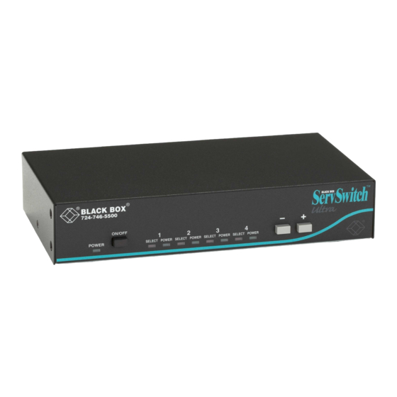
Page 16: The Front Panel
SERVSWITCH™ ULTRA 2.3 The Front Panel The front panels of the ServSwitch Ultra feature two or three pushbutton switches and several LED indicators. To familiarize yourself with these controls and indicators, refer to Figures 2-1, 2-2, and 2-3 below and the descriptions that follow on the next page. - Page 17 CHAPTER 2: Introduction Panel Label Description POWER (left) Main Power LED: Lights to indicate that unit is powered ON. ON/OFF 2-port units only: Press this button to turn the ServSwitch ON or OFF. [Numbered] CPU Status LEDs: Numbered pairs of LEDs indicate the status of the CPU or submaster (cascaded) Serv device connected to the corresponding port on the rear panel: SELECT or [unlabeled left] (red)
-
Page 18: The Rear Panel
SERVSWITCH™ ULTRA 2.4 The Rear Panel All cable connections are made at the rear panel of the ServSwitch Ultra, as illustrated in Figures 2-4 and 2-5 and described below. CPU3 CPU4 POWER 17VAC CT CPU1 CPU2 MONITOR/KEYBOARD/MOUSE RS-232 Figure 2-4. The rear panel of a 2 to 1 ServSwitch Ultra (KV5002MA-R2). CPU 15 CPU 16 CPU 13... - Page 19 CHAPTER 2: Introduction Panel Label Connector Description or Control CPU N DB25 F For each submaster you plan to connect, you must have an Expansion Cable; you must have (continued) an Adapter Cable for each CPU you plan to connect. See Section 2.5. NOTE The 2-port (mini) chassis has 4 CPU N connector slots;...
-
Page 20: Cable Requirements
SERVSWITCH™ ULTRA 2.5 Cable Requirements Many switches of this type have what seems like ten million connectors on their rear panels: one for each CPU’s video cable, one for each keyboard cable, and a third for each mouse cable. The potential for tangling or mismatching cables is high. -
Page 21: Installation
CHAPTER 3: Installation 3. Installation 3.1 Quick Setup Guide Figure 3-1, below, shows a basic example of connecting a CPU, a submaster, a keyboard, a monitor, and a mouse to the ServSwitch unit. IBM PC equipment is shown, but the basic principles will be similar for all equipment types. Connectors will vary depending on the types of equipment you are installing. -
Page 22: Installation Procedure
SERVSWITCH™ ULTRA 3.2 Installation Procedure This section provides complete instructions for the hardware setup of a single ServSwitch Ultra. (For detailed instructions on the capabilities and concerns involved in installing a cascaded Switch system, see Section 3.3; to make troubleshooting the installation easier, we recommend that you check the master and each submaster as it is installed, rather than installing all units, then checking the entire cascade.) For an illustrated example of the elements of a basic setup, see Figure 3-1 on the previous page. -
Page 23: Connecting Cpus
CHAPTER 3: Installation 3.2.3 C ONNECTING CPU Cables run from the ServSwitch to the keyboard port, mouse port, and video- output port of each CPU you want to directly attach to it. Different types of this cable fit the connectors on different computers (see Appendix B). This cable also comes in the different lengths supported by different applications (see Section 4.1.3). -
Page 24: Connecting Submasters (Optional)
ServSwitch Ultras (see Section 3.3), connect the CPU ports of one master to the submasters’ MONITOR/KEYBOARD/MOUSE A ports, and the CPU ports of the other master to the submasters’ MONITOR/KEYBOARD/MOUSE B ports. Before installing an advanced configuration, please call Black Box and discuss your application with a technician. -
Page 25: Powering Up The System
CHAPTER 3: Installation 3.2.5 P OWERING P THE YSTEM 3.2.5.A Initial Steps 1A. 2-port model (KV5002MA-R2): Making sure that the connected CPUs and any connected submasters are OFF (powered down), take the output cord of the ServSwitch Ultra’s power supply and plug its 5-pin DIN male connector into the power jack on the rear panel of the Switch. -
Page 26: C Remaining Steps If Any Cpus Aren't Sun Models
SERVSWITCH™ ULTRA keyboard and reattach the keyboard strand of the CPU cable; you can now use the Switch’s on-screen menu system (see Section 5.1) to change the keyboard settings of the all of your CPU ports to “Sun” (see Section 5.3). 4. -
Page 27: Changing The Keyboard Setting Of Windows Nt 4.0 Cpus
CHAPTER 3: Installation 3.2.6 C NT 4.0 CPU HANGING THE EYBOARD ETTING OF INDOWS If any CPUs attached to your ServSwitch Ultra are running Microsoft Windows NT 4.0, you must change the keyboard setting in their Control Panel from the default, “Microsoft Enhanced Keyboard,” to “Standard 101/102 or Microsoft Natural Keyboard.”... -
Page 28: Cascading In Servswitch Systems
SERVSWITCH™ ULTRA 3.3 Cascading in ServSwitch Ultra Systems In a normal cascaded ServSwitch Ultra system, the shared monitor(s), keyboard(s), and mouse (mice) are directly attached to one or more “master” ServSwitch Ultras, while all the CPUs are indirectly attached through “submasters” (subsidiary ServSwitch Ultras, regular ServSwitches, ServManagers, etc.) that provide port expansion but may or may not perform any control functions of their own. -
Page 29: Cable Requirements For Expansion
CHAPTER 3: Installation can only be accessed by the monitors, keyboards, and mice on that master. Note that when we say that CPUs 1 through 8 are “shared,” we mean that they can be accessed by either master at different times, not by both masters simultaneously.) Adding a third 4-port submaster unit would give you a total of 17 ports, and so on. - Page 30 SERVSWITCH™ ULTRA • You must not cascade submasters to more than one “layer.” That is, you may connect submasters to the CPU ports of one or (with Matrix ServSwitch submasters) two master ServSwitches, but do not connect any submasters to submasters’...
- Page 31 CHAPTER 3: Installation • If you are attaching more than one submaster to a slimline or full-size master ServSwitch Ultra, we strongly recommend that all of the submasters have the same number of ports. This is because the Switch’s “Expansion width” command/parameter—the value it uses to calculate how many ports each attached submaster has (see Section 5.2.5)—is global rather than submaster- specific.
- Page 32 SERVSWITCH™ ULTRA When you’re ready to begin hooking up the actual units, follow these steps: 1. If this hasn’t already been done, connect the monitor(s), keyboard(s), and mouse (mice) to the MONITOR/KEYBOARD/MOUSE port(s) of your master device(s) as outlined in Section 3.2.2. 2.
- Page 33 CHAPTER 3: Installation 8. You might need to set some or all of each master’s remaining configuration parameters, especially the keyboard mode for some of your ports (see Sections 5.2.1, 5.2.2, and 5.2.6 through 5.2.10). 9. Save the configuration changes you just made to the master unit’s nonvolatile memory as described in Section 5.1.3.
-
Page 34: Operation: Hardware And Keyboard Commands
SERVSWITCH™ ULTRA 4. Operation: Hardware and Keyboard Commands The first part of this chapter, Section 4.1, gives you some guidelines that you should follow to make sure your ServSwitch Ultra works properly with your equipment. Section 4.2 summarizes the ServSwitch Ultra’s keyboard commands, and Section 4.3 describes these commands in detail. -
Page 35: Mouse And Keyboard
CHAPTER 3: Installation 4.1.2 M OUSE AND EYBOARD When you power up your ServSwitch Ultra system, make sure that your CPUs, mouse (mice), and keyboard(s) are properly cabled to the Switch (or to the appropriate master or submaster unit). When you boot up your CPUs, the master(s) and/or submasters to which they are connected should already be ON. - Page 36 SERVSWITCH™ ULTRA • Because the ServSwitch Ultra currently only supports “stream mode” (continuous) mouse data, but older IBM ThinkPad models have to handle mouse data in “prompt mode” (burst-on-request), don’t try to attach any older ThinkPad computers to the Switch, either directly or through docking stations. Some newer models should work with the Switch, but there’s no good way to tell other than by trial and error—exercise caution! •...
- Page 37 CHAPTER 4: Operation: Hardware and Keyboard Commands Table 4-1. Keyboard Mapping by the ServSwitch Ultra Generally, the ServSwitch Ultra interprets keys by their positions on the keyboard, so any keys that occupy more or less the same positions and perform more or less the same functions across platforms will map one-to-one.
-
Page 38: Monitor
H/V and composite-sync input, or you will have to use a sync converter and special cables to convert H/V to composite sync or vice versa (call Black Box Technical Support for a special quote). - Page 39 CHAPTER 4: Operation: Hardware and Keyboard Commands The ServSwitch Ultra will support SVGA (Super VGA) video, but with original Serv cables the video quality will decrease markedly at higher resolutions and distances. Table 4-2, below, illustrates this. The distances in the table are total cable lengths measured from the CPU to the monitor.
- Page 40 CPUs before installing this cable in lengths greater than 20 ft. (6.1 m). For CPU-to-monitor distances over 200 feet (61 m) in IBM PC applications, Station Extenders or CAT5 KVM Extenders might be required. Call Black Box for technical support to discuss this option.
-
Page 41: Keyboard-Command Summary
CHAPTER 4: Operation: Hardware and Keyboard Commands 4.2 Keyboard-Command Summary Table 4-4 below and on the next two pages summarizes the commands that can be sent to the ServSwitch Ultra. To enter any command at the shared keyboard, first press and release the left Control key, represented by “[Ctrl].” (This cues the Switch to look for commands from that keyboard.) Then enter the command followed by any arguments you wish to specify (the port number, for example). - Page 42 SERVSWITCH™ ULTRA Table 4-4. The ServSwitch Ultra’s Keyboard Commands (continued) Command Keystroke Sequence Description Scan OFF [Ctrl] X Turns Scan mode OFF (the port being scanned at the time the command is entered is given access to the shared monitor, keyboard, and mouse). Note: Scan can also be stopped by entering a Select Port command.
-
Page 43: The Commands In Detail
CHAPTER 4: Operation: Hardware and Keyboard Commands Command Keystroke Sequence Description Activate Select [Ctrl] [ESC] Causes the ServSwitch Ultra to display its Window “computer select window” (see Section 5.5). Log Out [Ctrl] L Logs out the current user if an access password has been set;... -
Page 44: Scan Mode
SERVSWITCH™ ULTRA of the keyboard marked with [–] and [_]). The command is not case-sensitive. Do not use the [+] and [–] keys on the keyboard’s numeric pad; the Switch doesn’t recognize these. You can also select the next or previous port manually from the ServSwitch Ultra’s front panel by pushing the button labeled “... -
Page 45: Transpose Command And Alt Keys
CHAPTER 4: Operation: Hardware and Keyboard Commands 4.3.6 T RANSPOSE OMMAND AND This command is designed to make life easier for people used to the Sun or Mac keyboard who now need to use a Windows 95/Windows 98 style (104/105-key) PC type shared keyboard, or vice versa. -
Page 46: Send Null Byte (Ps/2 Type Mice Only)
SERVSWITCH™ ULTRA mouse but don’t disable the mouse either, take these precautions: • If you never actually use the mouse with the CPU (as would probably be the case if, for example, the CPU were a Novell ® NetWare ® file server), either don’t plug the mouse strand of the CPU Adapter Cable into the CPU’s mouse port, or don’t load a mouse driver at all. -
Page 47: Identify Rom
CHAPTER 4: Operation: Hardware and Keyboard Commands 4.3.9 I DENTIFY Unfortunately, as with all complex equipment, problems might arise with your ServSwitch Ultra that require the assistance of technical-support personnel. One of the things technicians might want to know when they attempt to diagnose and correct your problem is the revision level of your Switch’s ROM. -
Page 48: Activate On-Screen Menus
SERVSWITCH™ ULTRA 4.3.12 A CTIVATE CREEN ENUS You can use this command to cause the ServSwitch Ultra to display its on-screen overlay menus, beginning with the main menu (see Section 5.1.1). To issue the Activate On-Screen Menus command, press and release the left Control key, then press and release the [F12] key. -
Page 49: Using The Rs-232 Port
EIA/TIA RS-422/423 signal levels rather than RS-232, a special adapter or interface converter is required to connect them to the ServSwitch Ultra’s RS-232 port (call Black Box for technical support if you really want to do this). We strongly recommend that you use some other type of computer to make this connection. -
Page 50: Switching Ports Remotely (Optional)
SERVSWITCH™ ULTRA 4.4.2 S WITCHING ORTS EMOTELY PTIONAL To switch ports on a ServSwitch Ultra from a remote computer or terminal attached to the Switch’s RS-232 port, take these steps: 1. Set your computer for serial communication at 9600 bps, no parity, 8 data bits, and 1 stop bit. -
Page 51: Upgrading The Firmware (Flash Memory)
CHAPTER 4: Operation: Hardware and Keyboard Commands 4.4.3 U PGRADING THE IRMWARE LASH EMORY The ServSwitch Ultra has flash memory, which means its firmware may be reloaded (upgraded) in order to support new features or fix any problems in its operation. To get new firmware revisions when they become available, you can download them from our Web site at www.blackbox.com. - Page 52 1 and sends “Waiting for file...”. To abort, press “N” on the PC’s keyboard; the Switch skips ahead to the “Hit enter to boot” message shown in step 5, but the firmware will remain unchanged. If the trouble recurs and you can’t pinpoint it, call Black Box for technical support.
- Page 53 It should then send the message: Hit enter to continue (If you get an error message at any time during this phase, call Black Box for technical support.) 7. Press the Enter (or Return) key again. The Switch should return to normal operation with port 1 selected (LED 1 lit).
-
Page 54: B Upgrading The Firmware With The Dos Copy Command
MODE command or provide some other means of setting your serial ports to higher data rates. Call Black Box for technical support if you have difficulty finding such a utility program. 3. Make sure the ServSwitch Ultra is turned OFF, then turn it ON while holding in both the “... - Page 55 Once this phase is successfully completed, LED 3 will light. If, however, an error occurs, LED 3 will remain dark, and you’ll have to go back to step 3. If the second attempt doesn’t work, call Black Box for technical support.
-
Page 56: Operation: On-Screen Display
SERVSWITCH™ ULTRA 5. Operation: On-Screen Display 5.1 Overview You can use the ServSwitch Ultra’s on-screen display to: 1. Configure the ServSwitch Ultra through a series of configuration menus (trig- gered with the [Ctrl] [F12] command, where [Ctrl] is the left Control key). 2. -
Page 57: Navigating The Configuration
CHAPTER 5: Operation: On-Screen Display This menu and all other on-screen display windows appear “on top of” your computer video, assuming you are switched to a computer with active video. (If no video is present, then the background is black.) If the display is not synchronized, then you should switch to a computer with active video and configure the resolution setting from the “Configure overlay”... -
Page 58: The "Configure System" Page
SERVSWITCH™ ULTRA 5.2 The “Configure System” Page Use this page, shown in Figure 5-2 below, to view and change keyboard-type, mouse, expansion, scan, and keyboard-typematic settings. Access it from the main menu by hitting [Enter] when “Configure system” is highlighted. Configure system Keyboard and mouse type Keyboard... -
Page 59: Configure System: Mouse
CHAPTER 5: Operation: On-Screen Display be displayed here as “US,” “US/UNIX,” “French,” “Danish,” “German,” “Italian,” “Netherlands/Dutch,” “Norwegian,” “Portuguese,” “Spanish,” “Swedish/Finnish,” “Swiss-French,” “Swiss-German,” “United Kingdom,” “Korean,” “Taiwan,” “Japan,” “French-Canadian,” or “unknown.” (If the system is booted with no keyboard attached, the Switch will tell Sun CPUs that the keyboard language is “U.S.”) 5.2.2 C ONFIGURE YSTEM... - Page 60 SERVSWITCH™ ULTRA “PS/2 wheel” mice, such as the Microsoft IntelliMouse, are similar to regular mice, but have a clickable and scrollable wheel control instead of a middle button. “Serial 2-button mouse” refers to those mice that have serial RS-232 interfaces (usually with a DB9 connector), are Microsoft compatible, and use a 3-byte, 7-bit, 1200-bps, no-parity data format.
-
Page 61: Configure System: Maximum Computers
CHAPTER 5: Operation: On-Screen Display 5.2.3 C ONFIGURE YSTEM AXIMUM OMPUTERS This setting corresponds to the number of computers (CPUs) connected to the ServSwitch Ultra system. It comes in handy when you are cascading, or are only using some of the CPU ports on a single Switch: When the Switch knows how many CPUs there are, it can handle switching and scanning more intelligently. -
Page 62: Configure System: Expansion Units
SERVSWITCH™ ULTRA 5.2.4 C ONFIGURE YSTEM XPANSION NITS This setting corresponds to the number of “submaster” (expansion) Serv units that are connected to the main master ServSwitch Ultra. It helps to determine which CPU number is associated with which physical connector. If you aren’t cascading, this number should be set to zero. -
Page 63: Configure System: Scan Mode
CHAPTER 5: Operation: On-Screen Display 5.2.6 C ONFIGURE YSTEM This item determines the time, in seconds, that the ServSwitch Ultra will pause at each of the computers when scanning. The factory-default setting is 5 seconds. To change the scan time, press [Enter] while “Scan time” is highlighted. An “Input new value”... -
Page 64: Configure System: Typematic Delay
SERVSWITCH™ ULTRA Table 3-1. Typematic Rate Rate Value Actual Rate in Rate Value Actual Rate in Keystrokes per Keystrokes per Second Second 10.9 13.3 17.1 18.5 21.8 26.7 5.2.10 C (IBM C ONFIGURE YSTEM YPEMATIC ELAY OMPATIBLE EYBOARDS This item determines how soon keystrokes will begin to repeat after the operator begins holding down a key on the shared IBM PC compatible keyboard. -
Page 65: The "Configure Computers" Page
CHAPTER 5: Operation: On-Screen Display 5.3 The “Configure Computers” Page Use this page to set the name, keyboard type, and mouse type for each of the ServSwitch Ultra’s CPU ports. Access it from the main menu by hitting [Enter] when “Configure computers” is highlighted. The page is shown below in Figure 5-5. -
Page 66: Configure Computers: Computer Name
SERVSWITCH™ ULTRA 5.3.1 C ONFIGURE OMPUTERS OMPUTER Each computer can be given a name consisting of up to 16 characters. These names appear as labels in the “Computer select” window (see Section 5.5). To change a computer name, press [Enter] while the corresponding “Computer name”... -
Page 67: Configure Computers: Keyboard
CHAPTER 5: Operation: On-Screen Display 5.3.2 C ONFIGURE OMPUTERS EYBOARD Use this field to tell the ServSwitch Ultra what type of keyboard or keyboard mode (PC mode 1, 2, or 3, Apple, or Sun) a given CPU uses. To change a CPU port’s keyboard mode, press [Enter] while the corresponding “Keyboard”... -
Page 68: Configure Computers: Mouse
SERVSWITCH™ ULTRA Once all of your CPU ports have been configured for the proper keyboard mode, make sure you save the changes. 5.3.3 C ONFIGURE OMPUTERS OUSE Use this field to tell the ServSwitch Ultra what type of mouse a given IBM PC compatible CPU uses. -
Page 69: The "Configure Overlay" Page
CHAPTER 5: Operation: On-Screen Display 5.4 The “Configure Overlay” Page Use this page to set the color of the configuration menus, the resolution of video generated by the ServSwitch Ultra, the type and timing of the Switch-generated screen saver, the appearance of the “Computer select” window, and the appearance of the Switch-generated computer label (see Section 5.4.3.A). -
Page 70: B Resolution
SERVSWITCH™ ULTRA 5.4.1.B Resolution This item gives you maximum monitor-type flexibility by determining the resolution and refresh rate of the video signal that the ServSwitch Ultra sends to the shared monitor while the unit isn’t receiving any video from the CPU. The possible choices are: •... -
Page 71: D Screen-Saver Time
CHAPTER 5: Operation: On-Screen Display 5.4.1.D Screen-Saver Time This item determines how long (in seconds) the ServSwitch Ultra waits for shared- keyboard or -mouse activity before turning on its screen saver. The factory-default value for this option is 600 seconds (10 minutes). To change the screen-saver time, press [Enter] while “Screen saver time”... -
Page 72: Configure Overlay: Computer Label
SERVSWITCH™ ULTRA The range of horizontal (X) movement is represented by the numbers 0 to 64. The range of vertical (Y) movement is represented by the numbers 0 to 99. The window will wrap around the edge of the screen at minimum and maximum points. Factory defaults are X=3, Y=3. -
Page 73: C Show Computer Number
CHAPTER 5: Operation: On-Screen Display 5.4.3.C Show Computer Number This item determines whether or not the computer number is displayed along with the computer label. To change this setting, press [Enter] while “Show computer number” is highlighted. A yes/no input box appears. Use the arrow keys to select “Yes”... -
Page 74: The "Configure Security" Page
SERVSWITCH™ ULTRA 5.5 The “Configure Security” Page Use this page to set security options for the ServSwitch Ultra. Access this page, shown in Figure 5-10 below, from the main menu by hitting [Enter] when “Configure security” is highlighted. Configure security Security New password Configuration password... -
Page 75: The Access Timeout
Once you have successfully set these passwords, you should keep a record of them in a secure location; if nobody can remember a given password, you will have to call Black Box Technical Support for help to recover your system. To remove either of these passwords, delete the password and press Enter with... -
Page 76: The "Computer Select Window
SERVSWITCH™ ULTRA 5.6 The “Computer Select Window” You can bring up a “computer select window” on the shared monitor’s screen to select a specific computer from a list of computers attached to the ServSwitch Ultra. Access the window, shown in Figure 5-11 below, by pressing and releasing the left [Ctrl] key and then hitting the [Esc] (escape) key. -
Page 77: Troubleshooting
Now reconfigure the box to your desired settings. If you’re still having difficulty, refer to Section 6.2. If it doesn’t help you to solve your problem, call Black Box for technical support. -
Page 78: Common Problems
CPU that’s having the problem. If the CPU boots, the ServSwitch Ultra or submaster might be defective; call Black Box. H. If the CPU still doesn’t boot, the CPU’s keyboard or mouse port (or other components) might be defective. -
Page 79: Can't Switch Ports From Keyboard
CHAPTER 6: Troubleshooting 6.2.2 Y ’ WITCH ORTS FROM THE EYBOARD A. Can you do anything from the keyboard? If not, the keyboard strand of your MKM cable has probably come loose. Reconnect it. B. The ServSwitch Ultra might have lost power for less than three seconds. (This can cause the keyboard to lock up.) Disconnect the keyboard and plug it back in. -
Page 80: Servswitch Ultra Scans Or Switches To Empty Ports
SERVSWITCH™ ULTRA 6.2.5 T WITCH LTRA CANS OR WITCHES TO MPTY OR ONEXISTENT ORTS A. The “Maximum computers” setting is too high. (If any of the CPUs you can access are receiving garbage characters, this is a good indicator.) Set Maximum Ports to match the number of CPUs in your system. -
Page 81: Mouse Doesn't Move Pointer/Cursor
Station Extenders (our product codes AC253A etc.) or CAT5 KVM Extenders (our product codes ACU9001A etc.); call Black Box for technical support. See Section 4.1.3 and Appendix B. 6.2.11 Y... -
Page 82: Can't Access High-Resolution Mode
E. The CPU is sending video with sync on green, which the ServSwitch Ultra does not currently support. Call Black Box for technical support. F. If the video problem is not centered on the monitor, check the video strands of your cables. -
Page 83: Servswitch Ultra Doesn't Work With Dongle-Protected Software
6.2.18 Y ’ ASSWORD If you’ve lost your access password or configuration password and you have no record of what they are set to, you will have to call Black Box Technical Support. They will help you to recover your system. -
Page 84: Calling Black Box
6.3 Calling Black Box If you determine that your ServSwitch Ultra is malfunctioning, do not attempt to alter or repair the unit. It contains no user-serviceable parts. Contact Black Box Technical Support at 724-746-5500. Before you do, make a record of the history of the problem. We will be able to... -
Page 85: Appendix A: Nvram Factory Defaults
APPENDIX A: NVRAM Factory Defaults Appendix A: NVRAM Factory Defaults A.1 Keyboard-Command Settings The table below shows, for the ServSwitch Ultra’s keyboard-command configuration options, the default values stored in nonvolatile memory (NVRAM) when the ServSwitch Ultra is shipped from the factory. It also shows what commands or actions can change these settings for the Switch’s current operating period, as well as what commands or actions (if any) can save changed settings to NVRAM, so that they become the new defaults. -
Page 86: On-Screen Configuration Settings
SERVSWITCH™ ULTRA A.2 On-Screen Configuration Settings The table below and on the next page shows, for the ServSwitch Ultra’s saveable on-screen display options, the default values stored in nonvolatile memory (NVRAM) when the ServSwitch is shipped from the factory. Option Default setting System Keyboard... - Page 87 APPENDIX A: NVRAM Factory Defaults Option Default setting Computer label Background color Transparent blue Text color White Position X=3, Y=90 Show computer number Fade out 5 seconds Font 16x24 modern Security Configuration password None Access password None Access time 999 seconds (16 hours, 39 minutes)
-
Page 88: Appendix B: Cable Product Codes
CPUs as much as 200 ft. (61 m) away. If your monitor/keyboard/mouse-sharing system has cabling requirements that can’t be met by what you see here, call Black Box for a possible quote on custom cables or adapters. Standard User Cables:... - Page 89 APPENDIX B: Cable Product Codes Coaxial User Cables: Monitor Type Keyboard Type Mouse Type Product Code (Connector on Cable) (Connector on Cable) (Connector on Cable) VGA (HD15 female) IBM PC/AT (5-pin DIN female) Serial RS-232 (DB9 male) EHN270-0xxx VGA (HD15 female) IBM PS/2 (6-pin mini-DIN female) PS/2 (6-pin mini-DIN female) EHN283-0xxx Mac (DB15 female) Mac (4-pin mini-DIN female)
- Page 90 SERVSWITCH™ ULTRA Original ServSwitch to ServSwitch Expansion Cable: EHN055-0001 Coaxial ServSwitch-to-ServSwitch Expansion Cable: EHN274-0xxx 6-wire straight-through-pinned flat-satin cable with RJ-12 connectors for communicating with ServSwitch Ultra through its RS-232 port: EL06MS-MM (specify length) Mac Adapter for ServSwitch: KV99MA Station Extenders: CPU to ServSwitch Ultra (RS-232 Mouse): AC254A ServSwitch Ultra to Station (RS-232 Mouse): AC255A CPU to ServSwitch Ultra (PS/2 Style Mouse): AC257A...
-
Page 91: Appendix C: Pinout Of Rs-232 Port
APPENDIX C: Pinout of RS-232 Port Appendix C: Pinout of RS-232 Port The table below shows the pinout of the ServSwitch Ultra’s RJ-12 (“6-wire RJ-11”) female RS-232 port. Signal Name Abbrev. Direction Description Data Set Ready Input Reserved (not used) Data Terminal Ready Output Pulled high with 1-kΩ... -
Page 92: Appendix D: The Lk461 Keyboard
SERVSWITCH™ ULTRA Appendix D: The LK461 Keyboard Some of the computers manufactured by Compaq subsidiary Digital Equipment ® Corporation come with a special keyboard called the DEC LK461. The ServSwitch Ultra supports this keyboard by passing through unaltered the scan codes of certain proprietary keys (such as [Help] and [Do]) and remapping others (such as [PF1] through [PF4]). -
Page 93: Appendix E: Rackmounting Your Servswitch Ultra
APPENDIX E: Rackmounting the ServSwitch Ultra Appendix E: Rackmounting the ServSwitch Ultra If you want to mount your ServSwitch Ultra in a 19", 23", or 24" rack, make sure you get the right ServSwitch Rackmounting Kit: product code RMK19M, RMK23M, or RMK24M respectively for the mini-chassis Switch models, RMK19S, RMK23S, or RMK24S respectively for the slimline-chassis models, or RMK19F, RMK23F, or RMK24F respectively for the full-size-chassis models. - Page 94 NOTES...
- Page 95 NOTES...
- Page 96 NOTES...
Need help?
Do you have a question about the ServSwitch Ultra KV5002MA-R2 and is the answer not in the manual?
Questions and answers