Thermal Arc ARCMASTER 400TS Manuals
Manuals and User Guides for Thermal Arc ARCMASTER 400TS. We have 2 Thermal Arc ARCMASTER 400TS manuals available for free PDF download: Service Manual

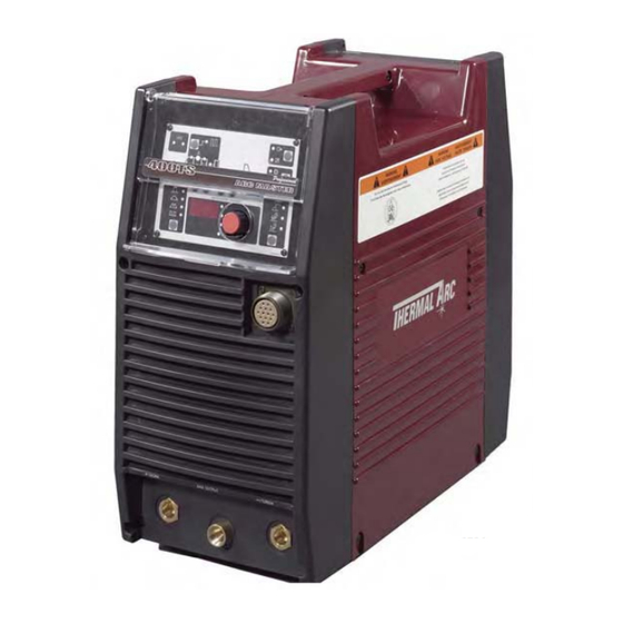
Thermal Arc ARCMASTER 400TS Service Manual (120 pages)
INVERTER ARC WELDERS Thermal Arc
Brand: Thermal Arc
|
Category: Inverter
|
Size: 11 MB
Table of Contents
Advertisement
Thermal Arc ARCMASTER 400TS Service Manual (120 pages)
INVERTER ARC WELDERS
Brand: Thermal Arc
|
Category: Welding System
|
Size: 5 MB
Table of Contents
Advertisement