
Related Manuals for Nice Apollo 1550ETL–1K


Summary of Contents for Nice Apollo 1550ETL–1K
- Page 1 Model 1550ETL–1K Single Swing Gate Operator Model 1650ETL-1K Dual Swing Gate Operator INSTALLATION MANUAL Rev 1.0...
-
Page 2: Table Of Contents
Table of contents IMPORTANT SAFETY INSTRUCTIONS …………………………………………………………...II APPLICATION ….……………………………………………………………………………………… III PRE-INSTALLATION CHECKLIST …………………………………...…………………..…….….. IV PART IDENTIFICATION ………………………………………...……………………………………….. V Optional parts identification 1. OPERATOR INSTALLATION ………………………………………………………..………… 7 1.1 - Pivot Arm Installation (standard pull to open) 1.2 - Actuator Installation 1.3 - Control Box Installation 1.4 - Apollo 816-1K limit switch and smart sensor wiring 1.5 - Apollo actuator motor wiring and connection to the controller 1.6 - Actuator connection at the controller... -
Page 3: Important Safety Instructions
IMPORTANT SAFETY INSTRUCTIONS WARNING - To reduce the risk of injury or death: READ AND FOLLOW ALL INSTRUCTIONS. Installation should be performed by a professional installer. Required welding should be performed by a qualified welder. Should electricity be required, use a certified electrician only. ... -
Page 4: Application
APPLICATIONS The Apollo Model 1550ETL-1K/1650ETL-1K Swing Gate Operator is approved for Vehicular Class I & II us- age under UL 325 Guidelines, and is designed to handle swing gates up to 16 feet in length and 600 pounds each. A professional fence or gate dealer is recommended to assure proper installation. Apollo Gate Operators are available only through qualified dealers with an outstanding reputation in the fence and gate industry. -
Page 5: Pre-Installation Checklist
PRE-INSTALLATION CHECKLIST The following check list should be used before beginning installation: Verify that the proper operator has been selected for this application. Verify proper installation and operation of the gate. 1. Are the hinges servicable? 2. Does the gate swing free and level? 3. -
Page 6: Part Identification
PART IDENTIFICATION Part# 816E Actuator with 8’ cable Part# 10025215 Gate Bracket (816EX slave actuator with 38’ cable (2 with 1650) supplied with 1650 Part# 11111B - CONTROL BOX Part# 1116 Pivot Arm (2 with 1650) Part# 1125 Hardware Kit Part# 273 - CAUTION Sign (2with 1650) (2 each) -
Page 7: Operator Installation
OPERATOR INSTALLATION 1.1 - PIVOT ARM INSTALLATION (standard pull to open) Location of Pivot Point. Notes: PULL TO OPEN pulls gate open (actuator is extended when gate is in the closed position). PUSH TO OPEN pushes the gate open (actuator is retracted when gate is in the closed position). For PUSH TO OPEN installations see page 11. -
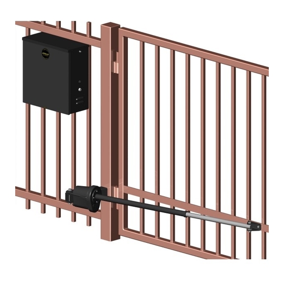
Page 8: Actuator Installation
IMPORTANT Never weld parts to the gate or posts when the operator circuit board is powered. Doing so may damage the board beyond repair. 1.2 - Actuator Installation 1/2” x 3 1/2” Hex Bolt 1/2” Washer Do not over tighten Nut and Bolt 1/2”... -
Page 9: Apollo Actuator Motor Wiring And Connection To The Controller
1.5 - Apollo actuator motor wiring and connection to the controller Connect the Apollo 816-1K actua- Apollo tor motor leads to the 3-pin con- 816-1K nector as shown in Figure 6. Red and Black black Note: If the gate moves in the opposite direction from what is expected, reverse the actuator wiring from what is shown in the... -
Page 10: Limit Switch Adjustment
1.8 - Limit Switch Adjustment 1. Install all gate accessories such as Photo-Eye’s, Sensors, Loops and other safety devices. 2. Apply battery power to the 1050 gate operator. Remove limit switch end caps 3. Remove the limit switch screw end caps from the Apollo 816-1K Series actuator. -
Page 11: Push To Open Installation
PUSH TO OPEN INSTALLATION 2.1 - PIVOT ARM(s) INSTALLATION Location of pivot point Direction of opening Hinge post Gate (closed) 6” Top View Both measurements are taken from the center of the hinge. 11” Figure 11: Pivot Arm Top View Center Line of attachment point for gate bracket Vertical position of... -
Page 12: Circuit Board Layout
3 - CIRCUIT BOARD LAYOUT Figure 15 - CONTROL BOARD BUTTONS Figure 16 - CIRCUIT BOARD LAYOUT... -
Page 13: Outputs & Inputs
4 - OUTPUTS & INPUTS Commercial Gate Operator Accessory Out- puts: OUT1 and OUT2: Individual, isolated relays provide COMMON, NORMALLY OPEN, and NORMALLY CLOSED dry contacts for switch- ing accessories based on programming of the “Auxiliary IO” function. These outputs are pro- grammed in the “FUNCTION Auxiliary I/O”... -
Page 14: Communication Buses
4.1 - Gate Operator Accessory Inputs (Continued) Guard Station Open: (34) Dry contact input for a guard station open switch. Momentarily shorting the digital input to GND opens the gate to the full open position with the subsequent auto-close fea- ture enabled. -
Page 15: Programming The Plug-In Receiver And Remote Controls
4.2.2 - Programming the plug-in receiver and remote controls SMXI/A Plugin Receiver: The SMXI/A 433Plug-In Receiver provides up to 15 channels for specific control of individual gate functions. The receiver includes built-in programming functions for adding or removing Nice FloR/A wireless remote con- trols to/from a gate installation. -
Page 16: Oview Remote Control
4.2.3 - OVIEW REMOTE CONTROL OVIEW (see page 6 for Picture of OVIEW) Programming and diagnostic unit which connects directly to the gate controller and is part of the Nice “Opera” control system. The unit can be used in “stand-alone” mode via its front-panel key- pad, or it may be accessed via a Bluetooth or cellular-enabled PDA, PC, or Smartphone when used with the O-View Software Suite. -
Page 17: Optional Inputs/Outputs
6 - OPTIONAL INPUTS/OUTPUTS 6.1 - Fire dept. connection 32 FIRE 33 GND Dry contact input for a fire department con- trol switch. Normally Open (NO) contact must be shorted to ground through a switch to open the gate. Figure 20 - FIRE DEPT. INPUT 6.2 - Exit and edge inputs wiring diagram 28 EDGE 29 GND... -
Page 18: Magnetic Lock Connection
6.4 - Magnetic lock connection 7 NC 8 Com (Common) 9 NO 10 GND 11 V+ This connection is used to install the magnetic lock. In this instance a gate can be locked magnetically to prevent a forced opening. Consult lock manual for specifics on installation and wiring. -
Page 19: General Layout And Safety Access
8 - GENERAL LAYOUT AND SAFETY ACCESS Figure 25 - LAYOUT FOR IN-GROUND LOOPS Figure 26 - LAYOUT FOR PHOTOCELLS... -
Page 20: Accessories And Sensors
9 - ACCESSORIES AND SENSORS EXTERNAL ENTRAPMENT PROTECTION: Non-contact and contact sensors must be installed individually or in combination with each other to provide external entrapment protection. Care should be exercised to reduce the risk of nuisance tripping, such as when a vehicle trips the sen- sor while the gate is still moving, and one or more non-contact sensors shall be located where the risk of entrapment or obstruction exists, such as the perimeter reachable by a moving gate or barrier. -
Page 21: Board Diagram
10 - BOARD DIAGRAM Figure 27 - GENERAL BOARD OVERVIEW THE PROGRAMMING BUTTONS INDICATED IN THE ABOVE REFERENCE SHOULD BE USED ONLY AFTER UNDERSTANDING THE MANUAL AND ITS RELATION TO THE PROGRAMMING SEQUENCES SHOWN ON THE FOLLOWING PAGES. CARE SHOULD BE TAKEN WHENEVER CHANGES ARE IMPLE- MENTED TO ENSURE PROPER FUNCTIONALITY AND SAFETY. -
Page 22: Programming Buttons
11 - PROGRAMMING BUTTONS 11.1 - Force Static: Set sensitivity to constant force on a scale of 1 to 10 (1 being the most sensitive). Dynamic: Set sensitivity of sudden impact force to the moving gate on a scale of 1 to 10 (1 being most sensitive). ESC: Exit the FORCE menu. -
Page 23: Function
11.5 - Function Learn: Puts the gate operator into learning mode for a Swing or Slide gate and Blue BUS peripherals. Learning mode for a Swing or Slide style gate involves selecting the gate type (Light, Average, Heavy), then fully opening and closing the gate to sense the limits. Select- ing the gate type selects precalculated values for the FORCE, SPEED, and ACCELERA- TION settings. - Page 24 11.5 - Function (continued) Radio Channel: For the Plug-in Onboard Receiver, 15 radio channels may be programmed with one of the following options: • No program • OPEN (Default CH. 2) • CLOSE • STEP (Default CH. 1) • PARTIAL •...
- Page 25 11.5 - Function (Continued) Timer (continued) To program weekly events EV1 through EV8, perform the following steps: 1. Press FUNCTION -> Events. 2. Press and hold OK to display EV1 (display will blink “EV1”). 3. Press UP or DOWN to toggle between events, then press OK to make a selection. The display changes to hours.
- Page 26 11.5 - Function (Continued) Advance Settings: The following settings are available for customizing the gate operator as required by the customer’s instal- lation requirements: Set Language (English, Spanish, Italian) Set clock 12H/24H Set LCD Contrast Direction of the Motor (only selectable in learning mode) ...
- Page 27 11.6 - Display ESC: Exit the DISPLAY menu. Info: Displays the manufacturer name, product name/model, software versions, and serial number. Clock: Displays the calendar date and time in the real time clock. Pressing and holding the “OK” button for 5 seconds enables the date and time settings to be updated manually. Main Volt: Displays the gate operator main control voltage in volts DC.
-
Page 28: Glossary
12 - GLOSSARY (Continued) CLASS IV - RESTRICTED ACCESS VEHICULAR GATE OPERATOR - A vehicular gate operator (or system) intended for use in a guarded industrial location or building such as an airport security area or other restricted access locations not servicing the general public, in which unauthorized ac- cess is prevented via supervision by security personnel. -
Page 29: Maintenance Schedule - Apollo Gate Opener
14 - MAINTENANCE SCHEDULE - APOLLO GATE OPENER TABLE 2 COMPLETE BASIC Active the primary (inherent) reverse system by blocking the gate with a solid object. The gate should reverse momentarily then stop. Alarm Restart the gate and Lock again with a solid object. The gate should ●... -
Page 30: Apollo 816-1K Programming Quick Start
16 - APOLLO 816-1K PROGRAMMING QUICK START Learning 816-1K actuator 1. Connect battery power to board. 2. Install all gate accessories such as Photo-Eye’s, Sensors, Loops and other safety devices. 3. Remove the limit switch screw end caps from the Apollo 816-1K Series actuator. See section 1.8 Apollo 816-1K Se- ries Limit Screw Adjustment. -
Page 31: Installation Checklist
18 - INSTALLATION CHECKLIST Left box is for installer check off and the right box is for customer check off. 1. The gate has been checked to make sure it is level and moves freely in both di- rections. 2. Potential pinch areas have been guarded so as to be inaccessible OR have con- tact and/or non-contact obstruction sensing devices installed. - Page 32 LIMITED TWO-YEAR WARRANTY Apollo Gate Operators are warranted against defects for a period of 24 months from the date of purchase, providing recommended installation procedures are followed. This warranty is in lieu of all other warranties expressed or implied (some states do not allow limitations on how long an implied warranty lasts, so this limitation may not apply to you) and shall be considered void if damage was due to improper installation or use, connection to improper power source, or if damage was caused by fire, flood, or lightning.
Need help?
Do you have a question about the 1550ETL–1K and is the answer not in the manual?
Questions and answers