
Related Manuals for Nice Apollo Titan 912L


Summary of Contents for Nice Apollo Titan 912L
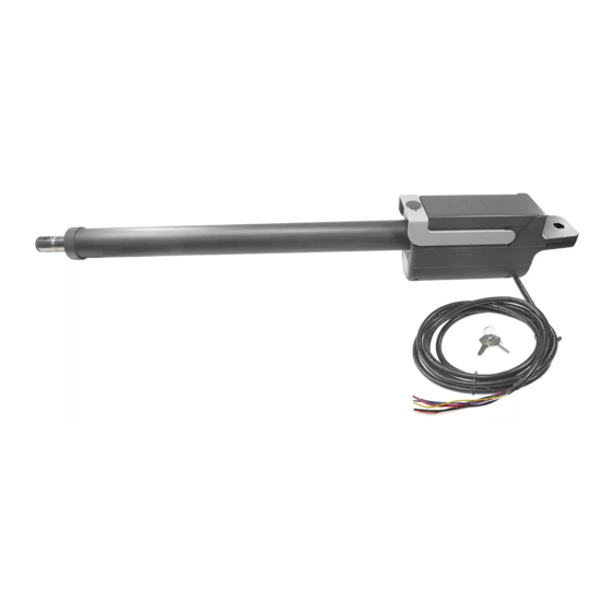
- Page 1 Vehicular Swing Gate Operator Nice Gate Operators Titan 912L The Titan 912L Gate Operator is intended for use with vehicular swing gates. The Titan 912L Gate Operator can be used in Class I, Class II and Class III applications.
- Page 2 TABLE OF CONTENTS...
-
Page 3: Table Of Contents
LIST OF FIGURES Figure 5-1 Left And Right Hand Swing Pivot Point Figure 5-2 Vertical Pivot Position Figure 5-3 Pivot Arm Installation Figure 5-4 Hinge Post Figure 5-5 Actuator Mounting Figure 5-6 Control Box Mounting Figure 5- 7 Incoming Power Wiring Figure 5-8 Manual Release Handle Figure 5-9 Titan Actuator Wiring... - Page 4 The Titan 912L swing gate operator delivers the next generation of easily installed, configured and maintained swing gate operators from Nice. With a maximum gate capacity of 600 lbs and 20 ft, this operator has a key lockable manual release, easily accessible limit switch settings as well as simple in-the-field maintenance and repair.
- Page 5 2.2 - Gate latches death. AUTOMATIC GATES ARE NOT FOR PEDESTRIANS! death. 2.4 - Swing and Slide Gates and slide g control point to or s lide autono periodic schedule. 2.5 - General requirements 3 - SAFETY AND CAUTIONS countles s WARNING IMPORTANT SAFETY INSTRUCTIONS WARNING - TO REDUCE THE RISK OF INJURY OR DEATH READ AND...
- Page 6 3.3 - Gate system safety devices main 3.4 - Infrared beams and warning signs them regu application. 3.5 - Establish the location 4.1 - Follow Instructions 4.2 - Intended usage 3.6 - Read and follow all instructions 3.7 - Keep children away 4.3 - Warnings, cautions and notes 3.8 - Test the gate system release.
- Page 7 4.3.16 Protrusions shall not be permitted on any gate, refer to ATSM 4.3.39 Safety sensors must be present at all times. The hard wired safety F2200 for exceptions, if any. sensors must be arranged and installed in such a manner so that 4.3.17 Gates shall not be designed, constructed and installed in such a the communication between gate operator and sensor(s) are never manner that gravity will cause or initiate movement in any direction...
-
Page 8: Figure 5-2 Vertical Pivot Position
5 - INSTALLATION PROCEDURES 5.1 - Pivot Arm Installation IMPORTANT - Never weld parts to the gate or posts when the operator circuit board is powered. Doing so may damage the board beyond repair. PULL TO OPEN INSTALLATION - PIVOT ARM INSTALLATION - Location of Pivot Point The following instructions provide up to 105°... -
Page 9: Figure 5-3 Pivot Arm Installation
5.2 - Push to open installation PIVOT ARM INSTALLATION - Location of Pivot Point Measurements are taken from the center of pivot of the gate hinge. The pivot arm needs to be securely mounted to the hinge post or equivalent mounting surface. It is recommended to weld the pivot arm to a metal post. -
Page 10: Figure 5-6 Control Box Mounting
5.4 - Control box mounting Mount the control box within 4 feet of the pivot arm. Use mounting hardware capable of supporting the weight of the control box with the battery installed. Do not mount the control box where the person using the push button on side of the box can come in contact with the gate. -
Page 11: Figure 5-8 Manual Release Handle
5.6 - Titan actuator wiring Using the supplied key, unlock the manual release handle. Lift upwards on the release handle as shown. FIGURE 5 - 8 MANUAL RELEASE HANDLE With the release handle up, remove the screws from the limit cover and remove the cover. On the bottom of the actuator loosen the strain relief nut and insert the wire into the actuator housing. -
Page 12: Figure 5-13 Actuator Motor Leads
Actuator Motor Wiring Actuator Motor Wiring Connect the actuator motor leads to the 3-pin connector Connect the actuator motor leads to the 3-pin connector as shown below. as shown below. NOTE NOTE Black Actuator Actuator Motor Leads Motor Leads Black NOTE: If gate moves in opposite NOTE: If gate moves in opposite direction from what is expected,... -
Page 13: Figure 5-16 Gate Bracket Mounting
5.8 - Limit switch adjustment From the manufacturer, these units will be in the fully retracted position. If the actuator is not mounted to the pivot arm, do so at this time, before proceeding (see Sec. 5.3). For a standard pull to open application, bring the gate leaf to the fully open position. - Page 14 5.9 - 1050 Controller learning proceedure Nice has taken great care to simplify the installation, operation and safety of this device and to ensure longevity and reliability of the unit over time. The learning procedure consists of the following steps shown below: NOTE The control board is already in LEARNING MODE when shipped.
-
Page 15: Figure 6-1 Board Outputs
GATE OPERATOR ACCESSORY INPUTS: 6 - ACCESSORY INPUTS AND OUTPUTS Auxiliary Inputs 1 (16) and 2 (18): These digital inputs may be connected 6.1 - OUTPUTS to the digital outputs of accessories and programmed to activate or control the gate operator in a number of different modes. Shorting the pins thr ough a dry contact activates the pr ogrammed settings for these inputs. -
Page 16: Figure 6-3 Communication Buses
6.3 - COMMUNICATION BUSES On the Slave operator, select Function -> Adv. Settings -> Remote Mst. Slv. Then select On -> Slave. The red LED associated with the Master/Slave connector will illuminate. identical open/close/stop functions in tandem with the Master gate operator. Programming the plug-in receiver and remote controls Nice Plug in Receiver: The Nice 433Plug-In Receiver provides up to 15... -
Page 17: Figure 7-1 Equipment Safety Warnings
Note: Double the amount of solar wattage for dual gate operators installation of this gate operator. • Nice Apollo operators with the 1050 board that are used in solar applications • Run individual circuits in separate U.L. listed conduits. Do not combine need to be put into “Standby” mode. -
Page 18: Figure 9-1 Fire Department Input
9 - OPTIONAL INPUTS 9.1 - FIRE DEPARTMENT CONNECTION 32 FIRE 33 GND contact must be shorted to ground through a switch to open the gate. The FAIL SAFE connector which is shorted at the factory with a jumper (Normally Closed NC), may be wired in parallel with the Fire input to release the a power failure. -
Page 19: Figure 10-1 Radio Receiver
10- RADIO RECEIVER CONNECTION (THIRD PARTY) 11 - INSPECTION AND OPERATION Proper inspection of all equipment is required to ensur e continuous functionality, safety and to ensure reliable operation in all weather conditions. 38 12V Inspect electrical assemblies and wiring installations for damage, general 39 OPEN condition, and proper functioning to ensure the continued satisfactory 40 CLOSE... -
Page 20: Figure 12-1 Layout For Inground Loops
12 - GENERAL LAYOUT AND SAFETY ACCESS Entrapment Protection Inputs - Typical Installation Diagram Utilizing Loop Sensors and Photocells Loop (Safety) Outside Gate 4’ Min. from closed gate 4’ Min. from closed gate Loop (Shadow) Photo 2 4’ Min. from open gate Photo 2 Loop (Safety) Loop (Exit) - Page 21 SECTION 13 - ACCESSORIES AND SENSORS EXTERNAL ENTRAPMENT PROTECTION Non-contact and contact sensors must be installed individually or in combination with each other to provide external entrapment protection. Care should be exercised to reduce the risk of nuisance tripping, such as when a vehicle trips the sensor while the gate is still moving, and one or mo contact sensors shall be located where the risk of entrapment or obstruction exists, such as the perimeter reachable by a moving gate or barrie A hardwired contact sensor shall be located and its wiring arranged so that the communication between the sensor and the gate o perator is not subjected to mechanical damage.
-
Page 22: Figure 13-3 Manual Release Disable
14 - MANUAL RELEASE/MANUAL OPERATION Manual Release 1. Lift rubber key cover and insert key into lock and rotate 90° clockwise. 2. Lift handle Safety Manual Lock 3. Operator is now in Manual In Released Position Mode. 90° FIGURE 13 -2 MANUAL RELEASE Manual Release Disengage 1. - Page 23 • Slow Down – Close: Sets the % of gate opening when the gate begins 15 - 1050 PROGRAMMING deceleration to the fully close position. • Partial: Sets the point in the % of gate opening when the gate begins when 15.1 - FORCE given a PARTIAL command.
- Page 24 be assigned to any combination of days of the week (Monday through • Set Anti-tailgate (Closes gate immediately after vehicle has cleared safety Sunday). Events that a re already programmed into the system may be sensors) suspended temporarily , or removed permanently from memory. The following •...
Need help?
Do you have a question about the Titan 912L and is the answer not in the manual?
Questions and answers
What battery specifications needed for 917L backup