
Related Manuals for Nice Apollo 73001K


Summary of Contents for Nice Apollo 73001K
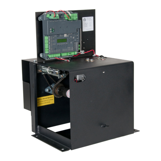
- Page 1 Nice Apollo Slide Gate Opener Model 73001K Vehicular Slide Gate Operator Revision 1.0.0.0_2-2014...
-
Page 3: Table Of Contents
TABLE OF CONTENTS CAUTIONS AND NOTES 17 - 120VAC POWER WIRING EXTREMELY IMPORTANT 18 - SOLAR PANEL CHART ETL DEFINITIONS COMPLIANT TO UL325 19 - OPTIONAL INPUTS 1 - OVERVIEW 19.1 - Fire dept. connection 1.1 - Main control board 19.2 - Magnetic lock connection 1.2 - Main control board specifics 19.3 - Guard station... -
Page 4: Cautions And Notes
CAUTIONS AND NOTES 1.1 - 1050 control board The 1050 main control board is housed in a protective plastic enclosure This instruction manual is intended to aid the installer in the overall process that includes a 2-line LCD and with 5 dedicated buttons and 3 buttons for of correct installation at the desired location. -
Page 5: Gate Latches
2.2 - Gate latches • Follow the recommended maintenance schedule of one inspection per every 180 days of use. In association with this gate controller and these operators, at no time should • Do not allow children to play in the area of the operator or to play with any manual gate latches or locks be used. -
Page 6: Gate System Safety Devices
3.3 - Gate system safety devices • A minimum of two (2) WARNING SIGNS shall be installed, one on each side of the gate where easily visible. Automatic gate operators are designed to move a heavy steel gate. Great • Test all features for proper functions before placing the automatic vehicular amounts of force are sometimes used to move these heavy systems. - Page 7 4.3.16 Protrusions shall not be permitted on any gate, refer to ASTM F2200 4.3.39 Safety sensors must be present at all times. The hard wired safety for exceptions, if any. sensors must be arranged and installed in such a manner so that the communication between gate operator and sensor(s) are never 4.3.17 Gates shall not be designed, constructed and installed in such a man- interrupted or severed by mechanical damage or movement.
-
Page 8: Circuit Board Layout
BlueBus Connection Master / Slave Earth Ground Connection Accessory Input Connections 6 - PARTS IDENTIFICATION Chain Bolts (2) Chain Bracket (2) #10003115 U-Bolts (4) #10020715 5/16” x 2” 73001K Control Box #40 Roller Chain (35’) and Master Links (2) #72520001... -
Page 9: Concrete Pad Location
7 - CONCRETE PAD LOCATION 14” Fabricate a concrete structure sufficient to stabilize and mount the operator. Consult local building codes to build a pad that meets or is sufficient for the soil type 3” and climate and capable of supporting the loads inposed by the operator during operation. -
Page 10: Incoming Power Wiring
Route chain through sprockets as shown. Make sure chain is level when attached to the chain brackets. Chain should be aligned with all sprockets. Attach the master link to one end of the chain and a chain bolt. Then attach the chain bolt to a chain bracket. Determine the required length of chain needed to attach the other chain bolt and still allow adjustment. -
Page 11: Limit And Motor Wiring
11 - LIMIT AND MOTOR WIRING LEFT CLOSING GATE - FACTORY DEFAULT RIGHT CLOSING GATE Limit switch wiring Limit switch wiring Connect the 7300 cable to the 5-pin connector as shown Connect the 7300 cable to the 5-pin connector as shown below. -
Page 12: Setting Limit Switches
13 - SETTING THE LIMIT SWITCHES The limit adjustments are located inside the control box between the circuit board and motor assembly as shown to the right. Limit adjustment assembly Decrease travel for movement to the right Increase travel for movement to the left Increase travel for movement to the right... -
Page 13: Quick Release Operation
14 - QUICK RELEASE OPERATION MAIN BATTERY POWER The quick release will allow for manual gate operation. Before disengaging the quick release make sure to disable power from the control board by unplugging the main and battery power terminals. Quick release assembly Engaged Disengage the quick release assembly by pulling the handle... -
Page 14: Learning Mode
15 - LEARNING MODE Apollo has taken great care to simplify the installation, operation and safety of this device and to ensure longevity and reliability of the unit over time. The learning procedure consists of the following steps shown below: UP SELECTION ARROW OK BUTTON DOWN SELECTION ARROW... -
Page 15: Accessory Inputs And Outputs
Commercial Gate Operator Accessory Inputs: 16 - ACCESSORY INPUTS AND OUTPUTS Auxiliary Inputs 1 (16) and 2 (18): These digital inputs may be connected to the digital outputs of accessories and programmed to activate or control the gate operator in a number of different modes. Shorting the pins through a 16.1 - Outputs dry contact activates the programmed settings for these inputs. -
Page 16: Communication Buses
16.3 - Communication buses On the Slave operator, select Function -> Adv. Settings -> Remote Mst. Slv. Then select On -> Slave. The red LED associated with the Master/Slave connector will illuminate. The Master/Slave pair is now configured. The Slave gate operator will perform identical open/close/stop functions in tandem with the Master gate operator. -
Page 17: 120Vac Power Wiring
Note: Double the amount of solar wattage for dual gate operators • All wiring connections MUST be made by a qualified individual Nice Apollo operators with the 1050 board that are used in solar applications • Run individual circuits in separate U.L. listed conduits. Do not combine need to be put into “Standby”... -
Page 18: Optional Inputs
19 - OPTIONAL INPUTS 19.1 - Fire dept. connection 32 FIRE 33 GND Dry contact input for a fire department control switch. Normally Open (NO) contact must be shorted to ground through a switch to open the gate. The FAIL SAFE connector which is shorted at the factory with a jumper C L O (Normally Closed NC), may be wired in parallel with the Fire input to release the... -
Page 19: Radio Receiver Connection (Third Party)
20 - INSPECTION AND OPERATION 19.5 - Radio receiver connection (third party) Proper inspection of all equipment is required to ensure continuous functionality, safety and to ensure reliable operation in all weather conditions. 38 12V Inspect electrical assemblies and wiring installations for damage, general 39 OPEN condition, and proper functioning to ensure the continued satisfactory 40 CLOSE... -
Page 20: General Layout And Safety Access
21 - GENERAL LAYOUT AND SAFETY ACCESS Entrapment Protection Inputs - Typical Installation Diagram Utilizing Loop Sensors and Photocells Loop (Safety) Outside Gate 4’ Min. from closed gate 4’ Min. from closed gate Photo 2 Loop (Safety) Loop (Exit) Figure - LAYOUT FOR IN-GROUND LOOPS Entrapment Protection Inputs - Typical Installation Diagram Utilizing Photocells Outside Photo... -
Page 21: Accessories And Sensors
22 - ACCESSORIES AND SENSORS EXTERNAL ENTRAPMENT PROTECTION Non-contact and contact sensors must be installed individually or in combination with each other to provide external entrapment protection. Care should be exercised to reduce the risk of nuisance tripping, such as when a vehicle trips the sensor while the gate is still moving, and one or more non- contact sensors shall be located where the risk of entrapment or obstruction exists, such as the perimeter reachable by a moving gate or barrier. -
Page 22: Board Nomenclature
23 - BOARD NOMENCLATURE Incoming 30 LCD screen Amp fuse Spare fuses Open the gate Stop gate movement Reset Hard Shut down button Close the gate Selection up OK or Enter Selection down Force select Speed select Delay select Function select Display select Figure - GENERAL BOARD OVERVIEW THE PROGRAMMING BUTTONS INDICATED IN THE ABOVE REFERENCE SHOULD BE USED ONLY AFTER UNDERSTANDING THE... -
Page 23: Programming Buttons
• Slow Down – Close: Sets the % of gate opening when the gate begins 24 - PROGRAMMING BUTTONS deceleration to the fully close position. • Partial: Sets the point in the % of gate opening when the gate begins when given a PARTIAL command. -
Page 24: Display
be assigned to any combination of days of the week (Monday through • Set Anti-tailgate (Closes gate immediately after vehicle has cleared safety Sunday). Events that are already programmed into the system may be sensors) suspended temporarily, or removed permanently from memory. The following •... -
Page 25: Emergency Vehicle Access
25 - EMERGENCY VEHICLE ACCESS 26 - GLOSSARY 25.1 The automatic vehicular gate system must be designed to allow LOCK- Ceases all operator function except HIGH PRIORITY inputs. access to emergency vehicles under different operating conditions. COMMERCIAL / GENERAL ACCESS VEHICULAR GATE OPERATOR- 25.2 During normal powered operation, emergency vehicles access the CLASS II - A vehicular gate operator (or system) intended for use in a gate by use of the emergency vehicle access device installed on your... -
Page 26: Maintenance Schedule
27 - MAINTENANCE SCHEDULE Table 2 COMPLETE BASIC Alarm Active the primary (inherent) reverse system by blocking the gate with a solid object. The gate should reverse momentarily then stop. Restart the gate and block again with a solid object. The ● ... -
Page 29: Warranty
31 - WARRANTY Nice Group USA Limited Warranty – 2 (TWO) YEARS Nice Group USA (“Manufacturer”) warrants this product shall be free from defects in materials and workmanship for a period of 2 years from the manufacture date. These warranties are in lieu of all other warranties expressed or implied and shall be considered void if the product is damaged due to, but not limited to, improper installation, improper use, terrorism or acts of God. -
Page 31: Installation Checklist
32 - INSTALLATION CHECKLIST Left box is for installer check off and the right box is for customer check off. ❑ ❑ 1. The gate has been checked to make sure it is level and moves freely in both directions. ❑ ❑ 2. Potential pinch areas have been guarded so as to be inaccessible OR have contact and/or non-contact obstruction sensing devices installed. - Page 32 Contact us Nice Group USA Inc. 12625 Wetmore Road Suite 218 San Antonio, TX 78247 Ph. +1.210.545.2900 Fax +1.210.545.2915 www.niceapollo.com www.facebook.com/NiceApollo...
Need help?
Do you have a question about the 73001K and is the answer not in the manual?
Questions and answers