Table of Contents
Advertisement
Quick Links
Advertisement
Table of Contents

Related Manuals for Elation CUEPIX PANEL


Summary of Contents for Elation CUEPIX PANEL
- Page 1 CUEPIX PANEL™ user manual ...
- Page 2 Elation Professional USA | 6122 S. Eastern Ave. | Los Angeles, CA. 90040 323-582-3322 | 323-832-9142 fax | www.elationlighting.com | info@elationlighting.com Elation Professional B.V.
-
Page 3: Table Of Contents
C O N T E N T S General Information Warranty Safety Instructions General Guidelines Fixture Overview Fixture Installation Understanding DMX Fixture Menu DMX Channel Functions And Values Cleaning and Maintenance Technical Specifications Optional Accessories CUEPIX PANEL™ User Manual Ver. 1... -
Page 4: General Information
INTRODUCTION Congratulations, you have just purchased one of the most innovative and ™ reliable lighting fixtures on the market today! The CUEPIX PANEL has been designed to perform reliably for years when the guidelines in this booklet are followed. Please read and understand the instructions in this manual carefully and thoroughly before attempting to operate this unit. - Page 5 You may also visit us on the web at www.elationlighting.com any comments or suggestions. For service related issue please contact Elation Professional®. ELATION SERVICE USA - Monday - Friday 8:00am to 5:00pm PST...
-
Page 6: Warranty
No accessories should be shipped with the product. If any accessories are shipped with the product, Elation Professional® shall have no liability what so ever for loss of or damage to any such accessories, nor for the safe return thereof. -
Page 7: Safety Instructions
Do not operate this fixture if the power cord has become frayed, crimped and/or damaged. If • the power cord is damaged, replace it immediately with a new one of similar power rating. CUEPIX PANEL™ User Manual Ver. 1... -
Page 8: General Guidelines
• Use the original packaging and materials to transport the fixture in for service. DO NOT TOUCH the housing bare-hand during its operation. Turn OFF the power • and allow approximately 15 minutes for the fixture to cool down before replacing or serving. CUEPIX PANEL™ User Manual Ver. 1... -
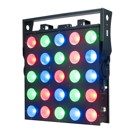
Page 9: Fixture Overview
4. powerCON IN 5. powerCON OUT 6. 3pin DMX OUT 7. 5pin DMX OUT 8. LCD Menu Control Display 9. ENTER Button 10. DOWN Button 11. UP Button 12. MODE/ESC Button 13. Safety Cable Rigging Points CUEPIX PANEL™ User Manual Ver. 1... -
Page 10: Fixture Installation
The CUEPIX PANEL provides an integrated yoke bracket. When mounting this fixture to truss be sure to secure an appropriately rated clamps to the yoke/rigging bracket using a M10 screw fitted through the center hole. CUEPIX PANEL™ User Manual Ver. 1... - Page 11 S A F E T Y C A B L E Always use a Safety Cable whenever installing this fixture in a suspended environment to ensure the fixture will not drop if the clamp fails. CUEPIX PANEL™ User Manual Ver. 1...
- Page 12 . e l a t i o n l i g h t i n g . c o m SECURING ™ Regardless of the rigging option you choose for your CUEPIX PANEL always be sure to secure your fixture with a safety cable. The fixture provides a built-in rigging point for a safety cable on the base of the unit as illustrated below.
-
Page 13: Understanding Dmx
1 to that fixture no matter where it is located in the DMX chain. The CUEPIX PANEL™ can be controlled via DMX-512 protocol and the DMX address is set via the control menu. - Page 14 Connect the provided XLR cable to the female XLR output of your controller and the other side to the male XLR input of the CUEPIX PANEL™ The diagram below illustrates a typical DMX-512 connection when the fixture is in the 79 Channel Mode. You can chain multiple panels together through serial linking.
- Page 15 5pin XLR fixtures may be implemented in a 3pin XLR DMX line. When inserting standard 5pin XLR connectors in to a 3pin line a cable adaptor must be used, these adaptors are readily available at most electric stores. The following chart details a proper cable conversion. CUEPIX PANEL™ User Manual Ver. 1...
- Page 16 In the case of the CUEPIX PANEL™, when in the 79 Channel Mode you should set the starting DMX address of the first unit to 1, the second unit to 80 (1 + 79), the third unit to 159 (80 + 79), and so on.
-
Page 17: Fixture Menu
The control panel (see image below) located on the top of the fixture allows you to access the main menu and make all necessary adjustments to the CUEPIX PANEL™. During normal operation, pressing MODE button once will access the fixture’s main menu. - Page 18 Set starting Pixel (COB module). Pixel Flip STANDARD, Flip 1, Flip 2, Flip 3, Flip 4 See Pixel Flip Section. Manual RGB R000-255 G000-255 B000-255 Set RGB Values manually for ALL 25 COB modules. CUEPIX PANEL™ User Manual Ver. 1...
- Page 19 Speed & Flash Adjustable Seven Color Chase 13.FLOW 8 Speed00-99 Flash00-99 Speed & Flash Adjustable Seven Color Chase 14.FLOW 9 Speed00-99 Flash00-99 Speed & Flash Adjustable Seven Color Chase 15.FLOW 10 Speed00-99 Flash00-99 Speed & Flash Adjustable CUEPIX PANEL™ User Manual Ver. 1...
- Page 20 PIXEL FLIP Select the desired starting COB module and chase direction from one of the following modes below via UP/DOWN buttons and then press ENTER to confirm. STANDARD FLIP 1 FLIP 2 FLIP 3 CUEPIX PANEL™ User Manual Ver. 1...
- Page 21 PIXEL FLIP [continued] FLIP 4 DIMMING CURVES The DimCurve menu allows you to select one of the following preset dimming curves: Standard, Stage, TV, Architectural, Theatre, or Default. (See diagram below for more details) Dimmer CUEPIX PANEL™ User Manual Ver. 1...
-
Page 22: Dmx Channel Functions And Values
*BLUE - COB MODULE 5 0-255 0 to 100% *RED - COB MODULE 6 0-255 0 to 100% *BLUE - COB MODULE 6 0-255 0 to 100% *GREEN - COB MODULE 6 0-255 0 to 100% CUEPIX PANEL™ User Manual Ver. 1... - Page 23 *GREEN - COB MODULE 12 0-255 0 to 100% *RED - COB MODULE 13 0-255 0 to 100% *GREEN - COB MODULE 13 0-255 0 to 100% *BLUE - COB MODULE 13 0-255 0 to 100% CUEPIX PANEL™ User Manual Ver. 1...
- Page 24 *GREEN - COB MODULE 19 0-255 0 to 100% *RED - COB MODULE 20 0-255 0 to 100% *BLUE - COB MODULE 20 0-255 0 to 100% *GREEN - COB MODULE 20 0-255 0 to 100% CUEPIX PANEL™ User Manual Ver. 1...
- Page 25 *GREEN - COB MODULE 24 0-255 0 to 100% *RED - COB MODULE 25 0-255 0 to 100% *BLUE - COB MODULE 25 0-255 0 to 100% *GREEN - COB MODULE 25 0-255 0 to 100% CUEPIX PANEL™ User Manual Ver. 1...
- Page 26 **DIMMER / SPEED Control SLOW to FAST FLASH / STROBE 0-255 Flash / Strobe Effect SLOW to FAST DIMMING CURVE MODES 0-41 STANDARD 42-84 STAGE 85-127 128-170 ARCHITECTURAL 171-213 THEATRE 214-255 Default to Unit Setting CUEPIX PANEL™ User Manual Ver. 1...
-
Page 27: Cleaning And Maintenance
Regular inspections are recommended to insure proper function and extended life. There are no user serviceable parts inside this fixture, please refer all other service issues to an authorized Elation service technician. Should you need any spare parts, please order genuine parts from your local Elation dealer. -
Page 28: Technical Specifications
Power Linking: 2pcs @120V / 4pcs @220V APPROVALS / RATINGS IP20 Please Note: Specifications and improvements in the design of this unit and this manual are subject to change without any prior written notice. CUEPIX PANEL™ User Manual Ver. 1... -
Page 29: Photometric Data
. e l a t i o n l i g h t i n g . c o m PHOTOMETRIC DATA DIMENSIONAL DRAWINGS Please Note: Specifications and improvements in the design of this unit and this manual are subject to change without any prior written notice. CUEPIX PANEL™ User Manual Ver. 1... - Page 30 . e l a t i o n l i g h t i n g . c o m DIMENSIONAL DRAWINGS [continued] Optional Rigging Bar Attached Please Note: Specifications and improvements in the design of this unit and this manual are subject to change without any prior written notice. CUEPIX PANEL™ User Manual Ver. 1...
-
Page 31: Optional Accessories
O P T I O N A L A C C E S S O R I E S ORDER CODE ITEM CRB001 CUEPIX PANEL Rigging Bracket For (4) Panels MAX CUE295/15LK CUEPIX PANEL 15 Degree Lens Kit TRIGGER CLAMP...
Need help?
Do you have a question about the CUEPIX PANEL and is the answer not in the manual?
Questions and answers