Table of Contents
Advertisement
Quick Links
Federal regulations require ceiling fans
with light kits manufactured or imported
after January 1, 2009, to limit total
wattage consumed by the light kit to
190W.
Therefore, this fan is equipped
with a wattage limiting device.
Installation Guide
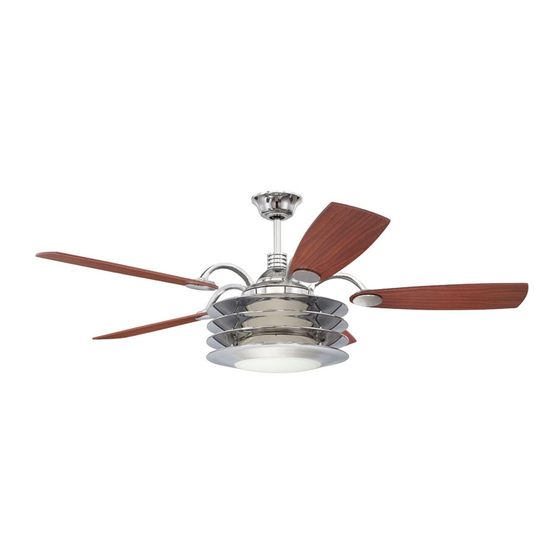
For Model:
E-ROU54CH5LKRW
E192641
net weight of fan: 26.81 lb (12.16 kg)
READ THESE INSTRUCTIONS
AND SAVE THEM FOR FUTURE USE
Table of Contents:
Safety Tips. pg. 1
Unpacking Your Fan. pg. 2
Parts Inventory. pg. 2
Installation Preparation. pg. 3
Hanging Bracket Installation. pg. 3
Fan Assembly. pgs. 4 - 5
Wiring. pgs. 5 - 6
Canopy Assembly. pg. 6
Blade Assembly. pg. 7
Motor Housing Assembly. pgs. 7 - 8
Light Kit Assembly. pg. 8
Wall Control Operation. pg. 9
Remote Control Operation. pg. 10
Testing Your Fan. pg. 10
Troubleshooting. pg. 11
Warranty. pg. 11
Parts Replacement. pg. 11
PRINTED IN CHINA
Advertisement
Table of Contents

Related Manuals for Ellington E-ROU54CH5LKRW


Summary of Contents for Ellington E-ROU54CH5LKRW
-
Page 1: Table Of Contents
Installation Guide Table of Contents: Safety Tips. pg. 1 For Model: Unpacking Your Fan. pg. 2 E-ROU54CH5LKRW Parts Inventory. pg. 2 Installation Preparation. pg. 3 Hanging Bracket Installation. pg. 3 Fan Assembly. pgs. 4 - 5 Wiring. pgs. 5 - 6 Canopy Assembly. -
Page 2: Safety Tips
SAFETY TIPS. WARNING: To reduce the risk of electrical shock, turn off the electricity to the fan at the main fuse box or circuit panel before you begin the fan installation or before servicing the fan or installing accessories. READ ALL INSTRUCTIONS AND SAFETY INFORMATION CAREFULLY BEFORE INSTALLING YOUR FAN AND SAVE THESE INSTRUCTIONS. -
Page 3: Unpacking Your Fan
1. Unpacking Your Fan. Carefully open the packaging. Remove items from Styrofoam inserts. Remove motor housing and place on carpet or Styrofoam to avoid damage to finish. Do not discard fan carton or Styrofoam inserts should this fan need to be returned for repairs. Check against parts inventory that all parts have been included. -
Page 4: Installation Preparation
3. Installation Preparation. blade edge To prevent personal injury and damage, ensure inches that the hanging location allows the blades a 7 feet (76cm) (2.13m) clearance of 7ft. (2.13m) from the floor and 30in. (76cm) from any wall or obstruction. 12ft. -
Page 5: Fan Assembly. Pgs
5. Fan Assembly. set screw set screw hole If you wish to extend the hanging length of your fan, stop pin you must remove the hanging ball from the 8in. downrod provided to use with an extended downrod (sold separately). [If you wish to use the 8in. downrod, hanging ball please proceed to instructions following the dotted line below.]... -
Page 6: Wiring. Pgs
5. Fan Assembly. (cont.) safety cable loop wood With the hanging bracket secured to the outlet ceiling box and able to support the fan, you are now joist ready to hang your fan. Grab the fan firmly with wood screw two hands. -
Page 7: Canopy Assembly
6. Wiring. (cont.) outlet box wall IN ORDER TO WIRE WALL CONTROL, remove existing control plate wall switch. Wire the WALL CONTROL with wire connectors provided as shown in diagram at right. * Wrap each wire connector separately with electrical green/ green/ green/... -
Page 8: Blade Assembly
8. Blade Assembly. blade Time Saver: Washers for blade screws can be screws set on each blade screw prior to installing and lock washers blades. Locate 15 blade attachment screws and blade attachment screws and washers washers in one of the hardware packs. Hold blade plate up to blade, aligning holes in blade arm blade plate with holes in blade as shown, and... -
Page 9: Light Kit Assembly
9. Motor Housing Assembly. (cont.) Remove 1 screw on motor plate (on underside of motor motor) and loosen the other 2 screws. Align slotted holes in center of the motor housing with loosened motor plate screws on motor plate, allowing the molex motor housing connections from motor to come through hole in middle of motor housing. -
Page 10: Automated Learning Process./Activating Code
11. Automated Learning Process./Activating Code. TRANSMITTER CAUTION: The remote control transmitter can be code (back) switches programmed to multiple receivers or fans. If this is not desired, turn wall switch off to any other programmable receiver or fan. Remove battery cover on back side of remote control transmitter. -
Page 11: Remote Control Operation
13. Remote Control Operation. HI button - turns fan to HIGH speed MED button - turns fan to MEDIUM speed LOW button - turns fan to LOW speed OFF button - turns fan OFF REV button - used to REVERSE blade direction (fan must be turned low before reversing blade direction) button - turns light ON/OFF 14. -
Page 12: Troubleshooting
Troubleshooting. Warranty. ELLINGTON LIFETIME LIMITED WARRANTY: WARNING: Failure to disconnect power supply ELLINGTON/LITEX INDUSTRIES, LTD. warrants this fan to the prior to troubleshooting any wiring issues may original household purchaser for indoor use under the result in serious injury. following provisions: Problem: Fan fails to operate.
Need help?
Do you have a question about the E-ROU54CH5LKRW and is the answer not in the manual?
Questions and answers