Table of Contents
Advertisement
Quick Links
Federal regulations require ceiling fans
with light kits manufactured or imported
after January 1, 2009, to limit total
wattage consumed by the light kit to
190W.
Therefore, this fan is equipped
with a wattage limiting device.
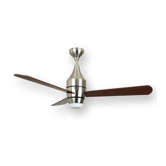
Installation Guide
For Models:
E-AML48ABZ3LKRW
E-AML48BNK3LKRW
E206035
net weight of fan: 13 lb (5.9 kg)
READ THESE INSTRUCTIONS AND
AND SAVE THEM FOR FUTURE USE
Table of Contents:
Safety Tips. pg. 1
Unpacking Your Fan. pg. 2
Parts Inventory. pg. 2
Installation Preparation. pg. 3
Hanging Bracket Installation. pg. 3
Fan Assembly. pgs. 4 - 5
Wiring. pgs. 5 - 6
Canopy Assembly. pg. 6
Blade Assembly. pg. 7
Light Kit Assembly. pgs. 7 - 8
Wall Control Operation. pg. 9
Remote Control Operation. pg. 9
Testing Your Fan. pg. 10
Troubleshooting. pg. 11
Warranty. pg. 11
Parts Replacement. pg. 11
PRINTED IN CHINA
Advertisement
Table of Contents

Related Manuals for Ellington E-AML48ABZ3LKRW


Summary of Contents for Ellington E-AML48ABZ3LKRW
-
Page 1: Table Of Contents
190W. Therefore, this fan is equipped with a wattage limiting device. Installation Guide For Models: E-AML48ABZ3LKRW Table of Contents: E-AML48BNK3LKRW Safety Tips. pg. 1 Unpacking Your Fan. pg. 2 Parts Inventory. pg. 2 Installation Preparation. -
Page 2: Safety Tips
SAFETY TIPS. WARNING: To reduce the risk of electrical shock, turn off the electricity to the fan at the main fuse box or circuit panel before you begin the fan installation or before servicing the fan or installing accessories. READ ALL INSTRUCTIONS AND SAFETY INFORMATION CAREFULLY BEFORE INSTALLING YOUR FAN AND SAVE THESE INSTRUCTIONS. -
Page 3: Unpacking Your Fan
1. Unpacking Your Fan. Carefully open the packaging. Remove items from Styrofoam inserts. Remove motor housing and place on carpet or Styrofoam to avoid damage to finish. Do not discard fan carton or Styrofoam inserts should this fan need to be returned for repairs. -
Page 4: Installation Preparation
3. Installation Preparation. blade edge To prevent personal injury and damage, ensure inches that the hanging location allows the blades a 7 feet (76 cm) clearance of 7 feet (2.13 m) from the floor and 30 (2.13 m) in (76 cm) from any wall or obstruction. 12 ft. -
Page 5: Fan Assembly. Pgs
5. Fan Assembly. set screw set screw hole stop pin If you wish to extend the hanging length of your fan, you must remove the hanging ball from the 8in. downrod provided to use with an extended downrod (sold separately). [If you wish to use the 8in. downrod, hanging ball please proceed to instructions following the dotted line below.]... -
Page 6: Wiring. Pgs
safety cable loop 5. Fan Assembly. (cont.) wood ceiling With the hanging bracket secured to the outlet box and joist able to support the fan, you are now ready to hang your wood screw fan. Grab the fan firmly with two hands. Slide downrod and washer through opening in hanging bracket and let hanging ball rest on the hanging bracket. -
Page 7: Canopy Assembly
6. Wiring. (cont.) IN ORDER TO WIRE WALL CONTROL, remove existing wall switch. Wire the WALL CONTROL with wire connectors provided as shown in diagram at outlet box right. wall control plate * Wrap each wire connector separately with electrical tape as an extra safety measure. Gently push wires and taped wire connectors into outlet gr green/ green/... -
Page 8: Blade Assembly
8. Blade Assembly. Loosen the screws in the 2 slotted holes inside the light kit fitter (located on the underside of the motor housing) and remove the other screw. Twist light kit fitter and pull down on carefully to remove. [Note: Make sure to check that molex plugs are disconnected BEFORE removing the light kit fitter from the motor housing. -
Page 9: Automated Learning Process./Activating Code
9. Light Kit Assembly. (cont.) Install the 75-watt mini can halogen bulb, type JD E11, provided. motor Tip: Do not touch glass portion of bulb with fingers or hands. Oil from skin housing can cause bulb to overheat and go out prematurely. Use cardboard box or foam wrapping bulb was packed with to layer around glass portion of bulb. -
Page 10: Wall Control Operation
11. Wall Control Operation. ON/OFF slider switch - turns wall control ON or OFF HI button - turns fan to HIGH speed MED button - turns fan to MEDIUM speed LOW button - turns fan to LOW speed FAN OFF button - turns fan OFF LIGHT button - turns light ON/OFF when pressed once;... -
Page 11: Testing Your Fan
13. Testing Your Fan. It is recommended that you test fan before finalizing installation. Restore power from circuit box and light switch (if applicable). Locate ON/OFF slider switch on wall control and set to the ON position. Test light and dimmer function and then test fan speeds. -
Page 12: Troubleshooting
Warranty. WARNING: Failure to disconnect power supply ELLINGTON LIFETIME LIMITED WARRANTY: prior to troubleshooting any wiring issues may ELLINGTON/LITEX INDUSTRIES, LTD. warrants this fan to the original household purchaser for indoor use under the result in serious injury. following provisions: 1-YEAR WARRANTY: ELLINGTON/LITEX INDUSTRIES, LTD.
Need help?
Do you have a question about the E-AML48ABZ3LKRW and is the answer not in the manual?
Questions and answers