Table of Contents
Advertisement
Available languages
Available languages
Quick Links
Federal regulations require ceiling fans
with light kits manufactured or imported
after January 1, 2009, to limit total
wattage consumed by the light kit to
190W.
Therefore, this fan is equipped
with a wattage limiting device.
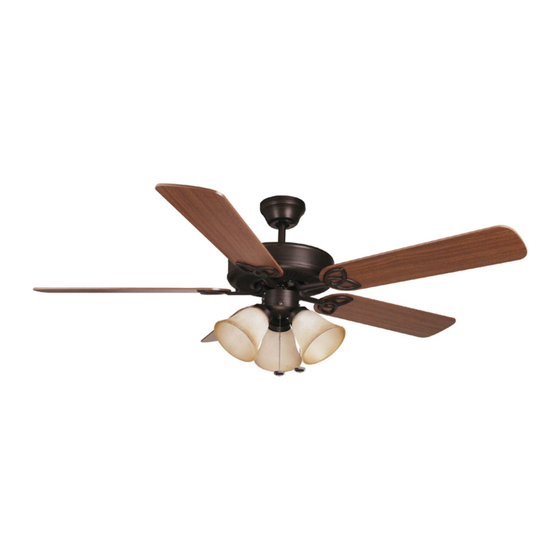
Installation Guide
For Models:
E-BLD52ABZ5C3
E-BLD52AN5C3
E-BLD52MWW5C3
E192641
net weight of fan: 21.03 lb. (9.54 kg)
READ THESE INSTRUCTIONS
AND SAVE THEM FOR FUTURE USE
Table of Contents:
Safety Tips. pg. 1
Unpacking Your Fan. pg. 2
Parts Inventory. pg. 2
Installation Preparation. pg. 3
Hanging Bracket Installation. pg. 3
Fan Assembly. pgs. 4 - 5
Wiring. pg. 6
Canopy Assembly. pg. 6
Blade Attachment. pg. 7
Testing Your Fan. pg. 8
Troubleshooting. pg. 9
Warranty. pg. 9
Parts Replacement. pg. 9
PRINTED IN CHINA
Advertisement
Table of Contents

Subscribe to Our Youtube Channel
Related Manuals for Ellington E-BLD52ABZ5C3


Summary of Contents for Ellington E-BLD52ABZ5C3
-
Page 1: Table Of Contents
190W. Therefore, this fan is equipped with a wattage limiting device. Installation Guide For Models: Table of Contents: E-BLD52ABZ5C3 Safety Tips. pg. 1 Unpacking Your Fan. pg. 2 E-BLD52AN5C3 Parts Inventory. pg. 2 E-BLD52MWW5C3 Installation Preparation. pg. 3 Hanging Bracket Installation. -
Page 2: Safety Tips
SAFETY TIPS. WARNING: To reduce the risk of electrical shock, turn off the electricity to the fan at the main fuse box or circuit panel before you begin the fan installation or before servicing the fan or installing accessories. READ ALL INSTRUCTIONS AND SAFETY INFORMATION CAREFULLY BEFORE INSTALLING YOUR FAN AND SAVE THESE INSTRUCTIONS. -
Page 3: Unpacking Your Fan
1. Unpacking Your Fan. Carefully open the packaging. Remove items from Styrofoam inserts. Remove motor housing and place on carpet or Styrofoam to avoid damage to finish. Do not discard fan carton or Styrofoam inserts should this fan need to be returned for repairs. -
Page 4: Installation Preparation
3. Installation Preparation. blade edge To prevent personal injury and damage, ensure that the hanging location allows the blades a inches 7 feet (76cm) clearance of 7 feet (2.13m) from the floor and (2.13m) 30in. (76 cm) from any wall or obstruction. This fan is suitable for room sizes up to 400 12ft. -
Page 5: Fan Assembly. Pgs
5. Fan Assembly (downrod). If you wish to extend the hanging length of your fan, you must remove the hanging ball from the set screw hole set screw 4in. downrod provided to use with an extended stop pin downrod (sold separately). [If you wish to use the 4in. - Page 6 5. Fan Assembly (downrod). (cont.) With the hanging bracket secured to the outlet box and able to support the fan, you are now ready to hang your fan. Grab the fan firmly with two hands. Slide downrod through opening in hanging hanging bracket tab bracket and let hanging ball rest on the hanging bracket.
-
Page 7: Wiring
7. Wiring. CAUTION: Be sure outlet box is properly grounded and that a ground (GREEN or Bare) wire is present. white supply wire ground Make sure all electrical connections comply with (green or bare) Local Codes or Ordinances and the National black supply wire Electrical Code. -
Page 8: Blade Attachment
9. Blade Attachment. Align the 3 blade screws, pre-installed on the blade arm, with the 3 holes on the blade. Press up on the blade arm firmly so y-connect that the blade screws come through the blade blade assembly holes in the blade. (Be careful not to use so piece much force that the blade arm bends.) Repeat for each blade arm. -
Page 9: Light Kit Assembly (Optional)
11. Light Kit Assembly (Optional). motor housing Remove socket ring from each light socket. Use 1 socket ring to attach each glass shade. Do not overtighten socket rings as glass may crack or break. Install 3 candelabra base 60 watt max. bulbs reverse switch (included). -
Page 10: Troubleshooting
Troubleshooting. Warranty. WARNING: Failure to disconnect power supply ELLINGTON LIMITED LIFETIME WARRANTY: ELLINGTON/LITEX INDUSTRIES, LTD. warrants this fan to the prior to troubleshooting any wiring issues may original household purchaser for indoor use under the result in serious injury. following provisions: 1-YEAR WARRANTY: ELLINGTON/LITEX INDUSTRIES, LTD. - Page 11 Por lo tanto, este ventilador tiene un aparato que sirve para limitar el vatiaje. Guía de instalación Para Modelos: Indice de materias: E-BLD52ABZ5C3 Sugerencias de seguridad. Pág. 1 Desempaquetado del ventilador. Pág. 2 E-BLD52AN5C3 Inventario de piezas. Pág. 2 E-BLD52MWW5C3 Preparación para la instalación.
- Page 12 SUGERENCIAS DE SEGURIDAD. ADVERTENCIA: Para evitar la posibilidad de una descarga eléctrica, desconectar la corriente en la caja de fusibles principal o el interruptor protector antes de iniciar la instalación del ventilador o antes de repararlo o instalar accesorios. LEER TODAS LAS INSTRUCCIONES E INFORMACIÓN DE SEGURIDAD CUIDADOSAMENTE ANTES DE INSTALAR SU VENTILADOR Y GUARDAR ESTAS INSTRUCCIONES.
- Page 13 1. Desempaquetado del ventilador. Abrir el empaque cuidadosamente. Sacar los artículos del embalaje. Sacar el motor y ponerlo en una alfombra o en el embalaje para evitar rayar el acabado. Guardar la caja de cartón o el empaquetamiento original en caso de que tenga que mandar el ventilador para alguna reparación.
- Page 14 3. Preparación para la instalación. borde del aspa Para prevenir daño corporal y otros daños, estar seguro de que el lugar en donde va a colgar el ventilador le 76cm permite un espacio libre de 2,13m (7 pies) entre las puntas de las aspas y el piso y 76cm (30 pulg.) entre las 2,13m pulg.)
- Page 15 5. Ensamblaje del ventilador (con tubo). agujero para el Si usted desea extender la longitud colgante del tornillo de fijación ventilador, usted tendrá que quitar la bola que se tornillo de fijación perno sirve para colgar del tubo de 10,16cm provisto para de tope usarla con un tubo más largo (a la venta por separado).
- Page 16 5. Ensamblaje del ventilador (con tubo). (cont.) Ya que esté sujetado el soporte de montaje a la caja de salida y capaz de apoyar el ventilador, usted está listo para colgar el ventilador. Agarrar el ventilador firmemente con las dos manos. Deslizar el tubo por la parte saliente del abertura del soporte de montaje y dejar que se soporte de montaje...
- Page 17 7. Instalación eléctrica. PRECAUCION: Asegurarse de que la caja de salida alambre conductor blanco toma de tierra esté conectada a tierra como es debido y que exista (verde o un conductor a tierra (VERDE o pelado). alambre conductor negro pelada) Asegurarse de que toda conexión eléctrica cumpla con los Códigos y las Ordenanzas Locales o el del techo...
- Page 18 9. Colocación de las aspas. Alinee los 3 tornillos para el aspa fijados de antemano en el brazo para el aspa con los 3 agujeros en el aspa. Empuje el brazo para el aspa hacia arriba firmemente para que pasen los mecanismo de aspa tornillos del aspa por los agujeros en la aspa.
- Page 19 11. Instalación del juego de luz (opcional). bastidor del motor Quitar el anillo de portalámpara de cada portalámpara en el conectador para el juego de luz. Usar 1 anillo de portalámpara para sujetar cada pantalla de vidrio. No apretar los anillos de portalámpara demasiado ya que el vidrio se puede rajar o romper.
- Page 20 Garantía. Localización de fallas. GARANTIA LIMITADA DE POR VIDA DE ELLINGTON: ADVERTENCIA: El no desconectar el suministro de ELLINGTON/LITEX INDUSTRIES, LTD. garantiza este fuerza eléctrica antes de hacer localización de fallas ventilador al comprador original de grupo familiar para para cualquier problema de instalación eléctrica uso interior con las siguientes condiciones: puede causar lesiones graves.
Need help?
Do you have a question about the E-BLD52ABZ5C3 and is the answer not in the manual?
Questions and answers