Table of Contents
Advertisement
Quick Links
Installation Guide
For Model:
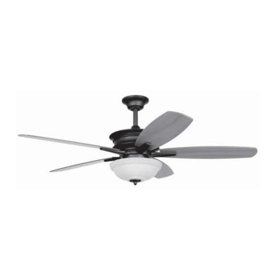
PNB52ESP5
E192641
net weight of fan: 18.96 lb. (8.6 kg)
READ THESE INSTRUCTIONS AND
SAVE THEM FOR FUTURE USE
Table of Contents:
Safety Tips. pg. 1
Unpacking Your Fan. pg. 2
Parts Inventory. pg. 2
Installation Preparation. pg. 3
Hanging Bracket Installation. pg. 3
Fan Assembly. pgs. 4 - 5
Wiring. pg. 6
Canopy Assembly. pg. 6
Blade Assembly. pg. 7
Testing Your Fan. pg. 9
Troubleshooting. pg. 10
Warranty. pg. 10
Parts Replacement. pg. 10
PRINTED IN CHINA
Advertisement
Table of Contents

Subscribe to Our Youtube Channel
Related Manuals for Ellington PNB52ESP5


Summary of Contents for Ellington PNB52ESP5
-
Page 1: Table Of Contents
READ THESE INSTRUCTIONS AND SAVE THEM FOR FUTURE USE Installation Guide For Model: PNB52ESP5 Table of Contents: Safety Tips. pg. 1 Unpacking Your Fan. pg. 2 Parts Inventory. pg. 2 Installation Preparation. pg. 3 Hanging Bracket Installation. pg. 3 Fan Assembly. pgs. 4 - 5 Wiring. -
Page 2: Safety Tips
SAFETY TIPS. WARNING: To reduce the risk of electrical shock, turn off the electricity to the fan at the main fuse box or circuit panel before you begin the fan installation or before servicing the fan or installing accessories. READ ALL INSTRUCTIONS AND SAFETY INFORMATION CAREFULLY BEFORE INSTALLING YOUR FAN AND SAVE THESE INSTRUCTIONS. -
Page 3: Unpacking Your Fan
1. Unpacking Your Fan. Carefully open the packaging. Remove items from Styrofoam inserts. Remove motor housing and place on carpet or Styrofoam to avoid damage to finish. Do not discard fan carton or Styrofoam inserts should this fan need to be returned for repairs. -
Page 4: Installation Preparation
3. Installation Preparation. blade edge To prevent personal injury and damage, ensure inches that the hanging location allows the blades a (76cm) 7 feet clearance of 7ft. (2,13m) from the floor and 30in. (2.13m) (76cm) from any wall or obstruction. This fan is suitable for room sizes up to 400 12ft. -
Page 5: Fan Assembly (With Downrod)
5. Fan Assembly (with downrod). set screw set screw hole If you wish to extend the hanging length of your stop pin fan, you must remove the hanging ball from the 4½in. downrod provided to use with an extended downrod (sold separately). [If you wish hanging ball to use the 4½in. -
Page 6: Fan Assembly. Pgs
5. Fan Assembly (with downrod). (cont.) wood ceiling With the hanging bracket secured to the outlet box and joist able to support the fan, you are now ready to hang your safety cable loop fan. Grab the fan firmly with two hands. Slide downrod through opening in hanging bracket and let hanging ball rest on the hanging bracket. -
Page 7: Wiring
7. Wiring. CAUTION: Be sure outlet box is properly grounded or that a ground wire (GREEN or Bare) is present. white supply wire ground (green or bare) black supply wire Make sure all electrical connections comply with Local Codes or Ordinances and the National Electrical Code. -
Page 8: Blade Assembly
9. Blade Assembly. Time Saver: Washers for blade screws can be set motor housing on each blade screw prior to installing blades. Locate 15 blade attachment screws and washers blade attachment screws plastic and washers in hardware pack. Hold blade arm up to blade and motor align holes. - Page 9 10. Light Kit Assembly (Optional). (cont.) reverse switch If you wish to use fan WITH the light kit, locate motor housing BLUE (or BLACK) and WHITE wires in the switch housing labeled FOR LIGHT KIT CONNECTIONS. Remove and discard plastic that holds these 2 wires together.
-
Page 10: Testing Your Fan
11. Testing Your Fan. It is recommended that you test fan before finalizing installation. Restore power from circuit box and wall switch (if applicable). Test fan speeds with the pull chain on the switch housing. Start at the OFF position (no blade reverse switch movement). -
Page 11: Troubleshooting
Troubleshooting. Warranty. WARNING: Failure to disconnect power supply ELLINGTON LIFETIME LIMITED WARRANTY: ELLINGTON/LITEX INDUSTRIES, LTD. warrants this fan to the prior to troubleshooting any wiring issues may original household purchaser for indoor use under the result in serious injury. following provisions: 1-YEAR WARRANTY: ELLINGTON/LITEX INDUSTRIES, LTD.
Need help?
Do you have a question about the PNB52ESP5 and is the answer not in the manual?
Questions and answers