Sign In
Upload
Manuals
Brands
Teledyne Manuals
Analytical Instruments
T802
Teledyne T802 Manuals
Manuals and User Guides for Teledyne T802. We have
1
Teledyne T802 manual available for free PDF download: Operation Manual
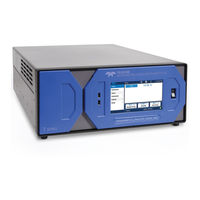
Teledyne T802 Operation Manual (314 pages)
PARAMAGNETIC OXYGEN ANALYZER
Brand:
Teledyne
| Category:
Analytical Instruments
| Size: 8.32 MB
Table of Contents
Safety Messages
5
Warranty
7
About this Manual
9
Table of Contents
11
Introduction, Features and Options
19
T802 Overview
19
Features
19
Options
20
Table 1-1. Analyzer Options
20
Specifications, Approvals & Compliance
23
Specifications
23
Table 2-1: T802 Specifications
23
Approvals and Certifications
24
Safety
24
Emc
24
Other Type Certifications
24
Getting Started
25
Unpacking the T802 Analyzer
25
Ventilation Clearance
27
Instrument Layout
27
Front Panel
27
Figure 3-1: Front Panel Layout
27
Table 3-1: Ventilation Clearance
27
Figure 3-2. Display Screen and Touch Control
28
Table 3-2. Display Screen and Touch Control Description
29
Figure 3-3.: Display/Touch Control Screen Mapped to Menu Charts
30
Figure 3-4: Rear Panel Layout
31
Table 3-3. Rear Panel Component Descriptions
32
Figure 3-5: Internal Layout
33
Connections and Setup
34
Electrical Connections
34
Figure 3-6: Analog in Connector
35
Table 3-4. Analog Input Pin Assignments
35
Figure 3-7: Analog Output Connector
36
Table 3-5: Analog Output Pin-Outs
36
Figure 3-8: Current Loop Option Installed
37
Figure 3-9: Status Output Connector
39
Table 3-6: Status Output Signals
39
Figure 3-10: Control Input Connector
40
Table 3-7: Control Input Signals
40
Figure 3-11: Concentration Alarm Relay
41
Figure 3-12: Default Pin Assignments, Rear Panel COM Port Connectors
43
Figure 3-13. CPU Connector Pin-Outs for RS-232 Mode
44
Figure 3-14: Jumper and Cables for Multidrop Mode
46
Figure 3-15: RS-232-Multidrop PCA Host/Analyzer Interconnect Diagram
47
Pneumatic Connections
48
Table 3-8: Nistsrms Available for Traceability of O
49
Figure 3-16: Pneumatic Connections-Basic Configuration-Using Bottled Span Gas
50
Figure 3-17: T802 Internal Gas Flow (Basic Configuration)
52
Figure 3-18: T802 - Internal Gas Flow with CO Sensor Option
53
Startup, Functional Checks, and Initial Calibration
54
Startup
54
Table 3-9: Front Panel Display During System Warm-Up
54
Figure 3-19: Viewing and Clearing T802 WARNING Messages
55
Functional Checks
56
Initial Calibration
57
Operating Instructions
63
Basic Operation
65
Overview of Operating Modes
65
Figure 4-1: Front Panel Touchscreen and Display
66
Table 4-1: Analyzer Operating Modes
66
Sample Mode
67
Figure 4-2: Viewing Test Functions
67
Calibration Mode
68
Table 4-2: Test Functions Defined
68
Setup Mode
69
Primary Setup Menu
69
Table 6-4: Primary Setup Mode Features and Functions
69
Secondary Setup Menu (Setup>More)
70
Table 6-5: Secondary Setup Mode Features and Functions
70
Setup Menu
71
SETUP CFG: Configuration Information
71
Setup Acal: [Not Used]
71
SETUP DAS: Internal Data Acquisition System
71
SETUP RNGE: Analog Output Reporting Range Configuration
72
Physical Range Versus Analog Output Reporting Ranges
72
Analog Output Ranges for O Concentration
73
Figure 5-1: Analog Output Connector Pin out
73
Reporting Range Modes
74
SETUP RNGE DIL: Using the Optional Dilution Ratio Feature
79
SETUP PASS: Password Feature
80
Setup Clk: Setting the T802 Analyzer'sinternal Clock
83
Setting the Internal Clock's Time and Day
83
Adjusting the Internal Clock's Speed
84
SETUP MORE COMM: Communication Ports
85
ID (Machine Identification)
85
INET (Ethernet)
86
COM1[COM2] (Mode, Baude Rate and Test Port)
87
SETUP more VARS: Internal Variables (VARS)
87
Table 5-2: Variable Names (VARS)
88
SETUP more DIAG: Diagnostics Functions
90
Signal I/O
92
Analog Output
93
Analog I/O Configuration
93
Table 5-4: DIAG - Analog I/O Functions
93
Table 5-5: Analog Output Voltage Range Min/Max
95
Table 5-6: Voltage Tolerances for the TEST CHANNEL Calibration
100
Figure 5-3: Setup for Checking / Calibration Current Output Signal Levels Using an Ammeter
102
Figure 5-4: Alternative Setup Using 250Ω Resistor for Checking Current Output Signal Levels
104
Table 5-7: Current Loop Output Check
104
Turning an Analog Output Over-Range Feature ON/OFF
105
Adding a Recorder Offset to an Analog Output
106
Selecting a Test Channel Function for Output A4
107
Table 5-8: Test Channels Functions Available on the T802'S Analog Output
107
AIN Calibration
109
Analog Inputs (XIN1
110
SETUP MORE ALRM: Using the Gas Concentration Alarms (Option 61)
111
Setting the T802 Option 61 Concentration Alarm Limits
112
Communications Setup and Operation
115
Data Terminal/Communication Equipment (DTE DCE)
115
Communication Modes, Baud Rate and Port Testing
115
COM Port Communication Modes
116
COM Port Baud Rate
118
COM Port Testing
119
Remote Access Via the Ethernet
120
Configuring the Ethernet Interface Using DHCP
120
Table 6-2: Ethernet Status Indicators
120
Table 6-3: Lan/Internet Configuration Properties
121
Manually Configuring the Network IP Addresses
123
USB Port for Remote Access
126
Communications Protocols
128
MODBUS Setup
128
Hessen
130
Table 6-4: RS-232 Communication Parameters for Hessen Protocol
130
Table 6-5: Teledyne API Hessen Protocol Response Modes
133
Table 6-6: Default Hessen Status Flag Assignments
137
Data Acquisition System (Das) & Apicom
140
Table 7-1: Front Panel LED Status Indicators for das
140
DAS Structure
141
DAS Channels
141
Default das Channels
142
Table 7-2: das Data Channel Properties
142
Figure 7-1: Default das Channel Setup
144
SETUP DAS VIEW: Viewing das Channels and Individual Records
145
SETUP DAS EDIT: Accessing the das Edit Mode
146
Table 7-3: das Data Parameter Functions
149
Remote das Configuration
159
DAS Configuration Via APICOM
159
DAS Configuration Via Terminal Emulation Programs
161
Figure 7-4: das Configuration through a Terminal Emulation Program
161
Remote Operation
162
Computer Mode
162
Remote Control Via APICOM
162
Interactive Mode
163
Remote Control Via a Terminal Emulation Program
163
Table 8-2: Teledyne API Serial I/O Command Types
164
Remote Access by Modem
166
COM Port Password Security
168
Calibration Procedures
171
Before Calibration
172
Required Equipment, Supplies, and Expendables
172
Calibration Gases
172
Data Recording Devices
173
Manual Calibration Checks and Calibration
174
Setup for Basic Calibration Checks and Calibration
174
Performing a Basic Manual Calibration Check
175
Performing a Basic Manual Calibration
176
Assessing Calibration Quality
178
Calibration of the T802'S Electronic Subsystems
178
Pressure Calibration
178
Table 9-2: Calibration Data Quality Evaluation
178
Flow Calibration
180
Calibration of the Optional CO Sensor
181
CO Calibration Setup
181
Set CO
181
Span Gas Concentration
181
Sensor Stability Function
182
CO Zero/Span Calibration
183
Maintenance and Service
185
Maintenance Schedule & Procedures
187
Maintenance Schedule
187
Table 10-1. T802 Maintenance Schedule
189
Table 10-2: T802 Test Function Record
190
Predictive Diagnostics
191
Maintenance Procedures
191
Replacing the Sample Particulate Filter
191
Table 10-3: Predictive Uses for Test Functions
191
Rebuilding the Sample Pump
192
Figure 10-1: Sample Particulate Filter Assembly
192
Performing Leak Checks
193
Performing a Sample Flow Check
194
Cleaning the Optical Bench
195
Cleaning Exterior Surfaces of the T802
195
Troubleshooting and Service
197
General Troubleshooting
197
Fault Diagnosis with WARNING Messages
198
Table 11-1: Warning Messages - Indicated Failures
200
Fault Diagnosis with TEST Functions
201
Diag Signal I/O: Using the Diagnostic Signal I/Ofunction
202
Table 11-2: Test Functions - Indicated Failures
202
Figure 11-2: Example of Signal I/O Function
203
Using the Internal Electronic Status Leds
204
CPU Status Indicator
204
Relay PCA Status Indicators
204
Table 11-3: Relay PCA Watchdog LED Failure Indications
204
Gas Flow Problems
205
Table 11-4: Relay PCA Status LED Failure Indications
205
Figure 11-5: T802– Basic Internal Gas Flow
206
T802 Internal Gas Flow Diagrams
206
Typical Sample Gas Flow Problems
207
Calibration Problems
209
Miscalibrated
209
Non-Repeatable Zero and Span
209
Inability to Span - no SPAN Button
210
Inability to Zero - no ZERO Button
210
Other Performance Problems
210
Temperature Problems
210
Subsystem Checkout
211
AC Mains Configuration
211
DC Power Supply
211
Table 11-5: DC Power Test Point and Wiring Color Codes
211
I 2 C Bus
212
Touchscreen Interface
212
LCD Display Module
212
Table 11-6: DC Power Supply Acceptable Levels
212
Relay Board
213
Sensor Assembly
213
Pressure/Flow Sensor Assembly
213
Motherboard
214
Table 11-7: Analog Output Test Function - Nominal Values Current Outputs
214
Cpu
215
Table 11-8: Status Outputs Check
215
Communications
216
Repair Procedures
217
Optional CO Sensor
217
Repairing Sample Flow Control Assembly
217
Sensor PCA
217
Disk-On-Module Replacement Procedure
218
Faq's
219
Technical Assistance
220
Principles of Operation
221
Paramagnetic Oxygen Measurement
221
Magnetic Properties of O Gas
221
Principle of Measurement
221
Sensor Design
222
Sensor Block Diagram
222
NDIR Measurement of CO
223
Operation Within the T802 Analyzer
224
Pneumatic Operation
224
Pneumatic Operation of the CO
225
Sensor
225
Flow Rate Control
226
Critical Flow Orifice
226
Particulate Filter
227
Pneumatic Sensors
227
Electronic Operation
228
Overview
228
Electronic Operation of the CO Sensor
229
Sensor Option
229
Figure 12-7: T802 Electronic Block Diagram
229
Central Processing Unit (CPU)
230
Relay Board
231
Figure 12-10: Relay PCA Layout (PN 04135)
232
Figure 12-11: Relay PCA with AC Relay Retainer in Place
233
Table 12-1: Relay PCA Status Leds
233
Figure 12-12: Status LED Locations – Relay PCA
234
Heater Control
234
Motherboard
234
Figure 12-13: Power Distribution Block Diagram
237
Front Panel Touch Screen/Display Interface
237
Optional CO 2 Sensor
237
Figure 12-14: Front Panel and Display Interface Block Diagram
238
Adaptive Filter
239
Figure 12-15: Basic Software Operation
239
Software Operation
239
Calibration - Slope and Offset
240
Internal Data Acquisition System (DAS)
240
Temperature and Pressure Compensation
240
A Primer on Electro-Static Discharge
241
How Static Charges Are Created
241
How Electro-Static Charges Cause Damage
242
Table 13-1: Static Generation Voltages for Typical Activities
242
Table 13-2: Sensitivity of Electronic Devices to Damage by ESD
242
Common Myths about ESD Damage
243
Basic Principles of Static Control
244
General Rules
244
Figure 13-2: Basic Anti-ESD Workbench
244
Basic Anti-ESD Procedures for Analyzer Repair and Maintenance
246
Models T802, 802E Appendix A Menu Trees (Reference: 06530C DCN6418)
255
APPENDIX A - Version Specific Software Documentation
255
APPENDIX A-1: Software Menu Trees, Software Versions 1.0.3 (T-Series)/A.3 (E-Series)
255
APPENDIX A-2: Setup Variables for Serial I/O, Software Versions 1.0.3 (T-Series)/A.3 (E-Series)
261
APPENDIX A-3: Warnings and Test Measurements, Software Versions 1.0.3 (T-Series)/A.3 (E-Series)
269
APPENDIX A-4: Signal I/O Definitions, Software Versions 1.0.3 (T-Series)/A.3 (E-Series)
272
APPENDIX A-5: das Triggering Events, Parameters, Software Version S 1.0.3 (T-Series)/A.3 (E-Series)
276
APPENDIX A-6: Terminal Command Designators, Software Versions 1.0.3 (T-Series)/A.3 (E-Series)
279
APPENDIX A-7: MODBUS Register Map, Software Versions 1.0.3 (T-Series)/A.3 (E-Series)
281
Advertisement
Advertisement
Related Products
Teledyne TURBO2
Teledyne TURBO2P
Teledyne Ultra Trace 3000
Teledyne TED 200-T
Teledyne T3AWG3352
Teledyne T3AWG3252
Teledyne T3AWG3354
Teledyne T3AWG3358
Teledyne T3AWG3258
Teledyne T3AWG325X
Teledyne Categories
Measuring Instruments
Analytical Instruments
Digital Camera
Test Equipment
Laboratory Equipment
More Teledyne Manuals
Login
Sign In
OR
Sign in with Facebook
Sign in with Google
Upload manual
Upload from disk
Upload from URL