Sign In
Upload
Manuals
Brands
Mitsubishi Electric Manuals
Amplifier
MELSERVO-J3W Series
Mitsubishi Electric MELSERVO-J3W Series Manuals
Manuals and User Guides for Mitsubishi Electric MELSERVO-J3W Series. We have
4
Mitsubishi Electric MELSERVO-J3W Series manuals available for free PDF download: Transition Handbook, Handbook, Instruction Manual, Manual
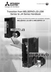
Mitsubishi Electric MELSERVO-J3W Series Transition Handbook (708 pages)
Brand:
Mitsubishi Electric
| Category:
Engine
| Size: 16.8 MB
Table of Contents
Table of Contents
10
Summary of Mr-J3/Mr-J3W Replacement
18
Major Replacement Target Model
19
Servo Amplifier Replacement Target Model
19
Servo Motor Replacement Target Model
19
Flow of Replacement
20
Summary
20
Flow of Review on Replacement
20
Configuration Diagram
21
Changes from MR-J3 Series to MR-J4 Series
22
Changes from MR-J3W Series to MR-J4 Series
24
Review on Replacement
26
Checking the System Prior to Replacement
26
Determination of Base Replacement Model
26
Attachment Compatibility Check
33
Detailed Review on Replacement Model
33
Peripheral Equipment Check
33
Startup Procedure Check
33
Related Materials
33
Catalog
33
Instruction Manual
33
Replacement Tool for Replacing MR-J3 with MR-J4
34
MITSUBISHI ELECTRIC FA Global Website
34
Summary
34
Case Study on Replacement of Mr-J3-_A
37
Review on Replacement Method
37
Replacement Method
37
Differences between Mr-J3-_A_ and Mr-J4-_A
39
Function Comparison Table
39
Comparison of Standard Connection Diagrams
42
List of Corresponding Connectors and Terminal Blocks
44
Comparison of Peripheral Equipment
49
Comparison of Parameters
50
Setting Requisite Parameters Upon Replacement
50
Parameter Comparison List
52
Comparison of Parameter Details
56
Important Points for Replacement
99
Part 3: Review on Replacement of MR-J3-_B_ with MR-J4-_B_ 3- 1 to
102
Case Study on Replacement of Mr-J3-_B
103
Review on Replacement Method
103
Replacement Method
104
Differences between Mr-J3-_B_ and Mr-J4-_B
107
Function Comparison Table
107
Comparison of Networks
110
Comparison of Standard Connection Diagrams
110
List of Corresponding Connectors and Terminal Blocks
111
Comparison of Peripheral Equipment
114
Comparison of Parameters
114
Setting Requisite Parameters Upon Replacement
115
Parameter Comparison List
116
Comparison of Parameter Details
119
Application of Functions
148
Part 4: Replacement of MR-J3W-_B with MR-J4W2-_B 4- 1 to
150
Case Study on Replacement of Mr-J3W-_B
151
Review on Replacement Method
151
Servo Amplifier Replacement Model
151
Replacement Method
152
Differences between Mr-J3W-_B and Mr-J4W2-_B
155
Function Comparison Table
155
Configuration Including Auxiliary Equipment
157
Comparison of Networks
161
Comparison of Standard Connection Diagrams
161
List of Corresponding Connectors and Terminal Blocks
163
Class
163
DC/24 V DC Class
166
Comparison of Peripheral Equipment
168
Comparison of Parameters
169
Setting Requisite Parameters Upon Replacement
170
Parameter Comparison List
171
Comparison of Parameter Details
175
Application of Functions
200
Part 5: Review on Replacement of MR-J3-DU_ with MR-J4-DU_ 5- 1 to
202
Functions and Configuration
203
Differences between MR-J3-DU_ and MR-J4-DU
203
Combination of Converter Unit, Drive Unit, and Servo Motor
204
Configuration Including Peripheral Equipment
206
Installation
208
Installation Direction and Clearances
208
Magnetic Contactor Control Connector (CNP1)
210
Signals and Wiring
212
Comparison of Standard Connection Diagrams
212
When Magnetic Contactor Drive Output Is Enabled (Factory Setting)
212
When Magnetic Contactor Control Connector (CNP1) Is Made Invalid
217
Power-On Sequence
222
List of Corresponding Connectors and Terminal Blocks
230
Converter Unit
230
Converter Unit Parameter Comparison List
238
Converter Unit Comparison of Parameter Details
239
Drive Unit
242
Drive Unit Comparison of Parameter Details
242
Characteristics
244
Overload Protection Characteristics
244
Power Supply Capacity and Generated Loss
247
Inrush Currents at Power-On of Main Circuit/Control Circuit
249
Options and Peripheral Equipment
250
Comparison Table of Cable Option Combinations
250
MR-J3CDL05M (0.5 M) Protection Coordination Cable
251
Selection Example of Wires
252
MR-J3 Series, Power Supply Wire Size
252
MR-J4 Series, Power Supply Wire Size
254
Selection of Molded-Case Circuit Breakers, Fuses, Magnetic Contactors (Example)
256
MR-J3-DU_ Molded-Case Circuit Breakers, Fuses, Magnetic Contactors (Recommended)
256
MR-J4-DU_ Molded-Case Circuit Breakers, Fuses, Magnetic Contactors (Recommended)
256
BU2-(H) Brake Unit
258
Selection
258
Brake Unit Parameter Setting
259
Connection Example
259
Dimensions
275
Regenerative Option
277
Combination and Regenerative Power
277
External Dynamic Brake
278
MR-J3 Series
278
MR-J4 Series
279
Part 6: Review on Replacement of MR-J3-_T_(DIO Command/ Serial Communication Operation) with MR-J4-_A_-RJ
280
CASE STUDY on REPLACEMENT of MR-J3-_T_(DIO Command/Serial Communication Operation)
282
Review on Replacement Method
282
Replacement Method
284
DIFFERENCES between MR-J3-_T_(DIO Command/Serial Communication Operation) and MR-J4
287
Function Comparison Table
287
DIO Command/Serial Communication Operation Specifications
294
Function List
296
Configuration Including Auxiliary Equipment
299
Comparison of Standard Connection Diagrams
303
List of Corresponding Connectors and Terminal Blocks
309
Comparison of Peripheral Equipment
316
Mr-J3-_T_ Mr-J4-_A_-Rj
316
Extension I/O Unit
316
Comparison of Parameters
317
Setting Requisite Parameters Upon Replacement
317
Parameter Comparison List
320
Comparison of Parameter Details
323
Important Points for Replacement
365
Communication Function
368
Command and Data No. List
368
Reading Command Comparison between MR-J3-_T_ and MR-J4-_A_-RJ
368
[Pr. PT01]: "1
369
[Pr. PT01]: "1
370
Specification Differences
379
Detailed Specification/Function Differences
379
Servo Amplifier
381
Main Circuit Terminal Block
381
Comparison of Encoder Signals (CN2)
386
Dynamic Brake: Coasting Distance
387
Forced Stop Deceleration Function Selection
397
Servo Setup Software: Setup Software (SETUP221E) => MR Configurator2
399
Servo Amplifier Initializing Time
400
The Pulse Width of the Encoder Z-Phase Pulse
403
Overload Protection Characteristics
404
Comparison of Networks
411
Comparison of Servo System Network Specifications
411
Servo Amplifier Dimensions/Attachment Differences
413
MR-J3 Series => MR-J4 Series Comparison Table of Servo Amplifier Dimensions/Installation Differences
413
General-Purpose Interface/Sscnet Interface/Dio, Serial Communication 200 V/100 V Class (22 Kw or Less)
413
General-Purpose Interface/Sscnet Interface/Dio, Serial Communication 400 V Class (22 Kw or Less)
418
Dimensions of MR-J3-D01/MR-D01
422
General Purpose Interface/Sscnet Interface 200 V Class (30 Kw or More)
423
General Purpose Interface/Sscnet Interface 400 V Class (30 Kw or More)
425
SSCNET Interface (MR-J3W Series)
427
Parameter Conversion
428
Operation Procedure of Parameter Conversion
428
MR-J3-_A_/MR-J3-_T_ Parameter Diversion Procedure
429
Parameter Reading from the Servo Amplifier MR- J3-_A_/MR-J3-_T
429
Converting the Parameters of MR-J3-_A_/MR-J3-_T_ and Writing Them to the MR-J4-_A
429
Conversion Rules (MR-J3-_A_ => MR-J4-_A_)
435
Parameters that Need to be Checked after Parameter Conversion
440
Conversion Rules (MR-J3-_T_(DIO Command/ Serial Communication Operation) => MR-J4
441
Parameters that Need to be Checked after Parameter Conversion
449
MR-J3-_B_ and MR-J3W-_B Parameter Diversion Procedure
450
Changing QD75MH to QD77MS/LD77MS
451
Changing Q17Nhcpu/Q17Ndcpu/Q170Mcpu to Q17Ndscpu/Q170Mscpu(-S1)
453
Conversion Rules (MR-J3-_B_ and MR-J3W-_B => MR-J4-_B_ and MR-J4W2-_B)
455
Parameters that Need to be Checked after Parameter Conversion
460
Common Points to Note
462
Method for Checking the Software Version
462
Checking with MR Configurator2 (SW1DNC-MRC2-E)
462
Communication Function (Mitsubishi General-Purpose Ac Servo Protocol)
463
Structure
464
Configuration Diagram
464
Precautions for Using RS-422/RS-232C/USB Communication Function
466
Communication Specifications
467
Outline of Communication
467
Parameter Setting
467
Protocol
468
Transmission Data Configuration
468
Character Codes
469
Error Codes
470
Checksum
470
Time-Out Processing
470
Retry Processing
471
Initialization
471
Communication Procedure Example
472
Command and Data No. List
473
Reading Command
473
Writing Commands
478
Detailed Explanations of Commands
480
Data Processing
480
Status Display Mode
482
Parameter
483
External I/O Signal Status (DIO Diagnosis)
487
Input Device On/Off
490
Disabling/Enabling I/O Devices (DIO)
491
Input Devices On/Off (Test Operation)
492
Test Operation Mode
493
Output Signal Pin On/Off (Output Signal (DO) Forced Output)
497
Alarm History
498
Current Alarm
499
Other Commands
500
Hf-_P/Ha-_P/Hc-_P Motor Drive
502
MR-J3 Series Servo Motors Which Are Available with MR-J4-_A_ and MR-J4-_B
502
MR-J3 Series Servo Motors Which Are Available with MR-J4W_-_B
508
Application of Functions
510
J3 Compatibility Mode
510
J3 Outline of J3 Compatibility Mode
510
Operation Modes Supported by J3 Compatibility Mode
510
J3 Compatibility Mode Supported Function List
511
Distinguishing J3 Compatibility Mode
513
How to Switch J4 Mode/J3 Compatibility Mode
514
How to Use the J3 Compatibility Mode
515
Cautions for Switching J4 Mode/J3 Compatibility Mode
516
Cautions for the J3 Compatibility Mode
516
Change of Specifications of "J3 Compatibility Mode" Switching Process
517
J3 Extension Function
520
Master-Slave Operation Function
522
Scale Measurement Function
526
Functions and Configuration
526
Scale Measurement Encoder
528
How to Use Scale Measurement Function
531
Part 8: Review on Replacement of Motor 8- 1 to
534
Servo Motor Replacement
535
Servo Motor Substitute Model and Compatibility
535
Comparison of Servo Motor Specifications
546
Comparison of Servo Motor Mounting Dimensions
546
Detailed Comparison of Servo Motor Mounting Dimensions
552
Comparison of Mounting Dimensions for Geared Servo Motors
555
Comparison of Actual Reduction Ratios for Geared Servo Motors
558
Comparison of Moment of Inertia
559
Comparison of Servo Motor Connector Specifications
570
Comparison of Servo Motor Torque Characteristics
591
Part 9: Review on Replacement of Optional Peripheral Equipment 9- 1 to
602
Comparison Table of Regenerative Option Combinations
603
Regenerative Options 200 V Class /100 V Class
604
Combination and Regenerative Power for the MR-J3/MR-J3W Series
604
Combination and Regenerative Power for MR-J4 Series (Replacement Model)
605
External Form Comparison
606
Regenerative Options 400 V Class
607
Combination and Regenerative Power for the MR-J3 Series
607
Combination and Regenerative Power for MR-J4 Series (Replacement Model)
608
External Form Comparison
609
Comparison Table of Dynamic Brake Option Combinations
611
External Form Comparison
612
Comparison Table of Cable Option Combinations
613
Changes from MR-J3 Series to MR-J4 Series
613
Changes from MR-J3W Series to MR-J4W2-_B Servo Amplifier
615
Power Supply Wire Size
616
Selection of Power Supply Wire Size (Example)
616
MR-J3 Series Power Supply Wire Size
616
MR-J4 Series Power Supply Wire Size
620
MR-J3W Series Power Supply Wire Size
622
MR-J4W2-_B Servo Amplifier, Power Supply Wire Size
624
Selection Example of Crimp Terminals
626
MR-J3 Series Crimp Terminal
626
MR-J4 Series Crimp Terminal
627
Selection of Molded-Case Circuit Breaker, Fuse, and Magnetic Contactor (Example)
628
MR-J3 Series, Molded-Case Circuit Breakers, Fuses, and Magnetic Contactors
628
MR-J4 Series, Molded-Case Circuit Breakers, Fuses, and Magnetic Contactors (Recommended)
629
MR-J3W Series, No-Fuse Breakers, Fuses, Magnetic Contactors
631
MR-J4W2-_B Servo Amplifier, No-Fuse Breakers, Fuses, Magnetic Contactors
632
Battery
634
Combinations of Batteries and the Servo Amplifier
634
MR-J3 Series Battery
635
MR-J4 Series Battery
636
Battery Replacement Procedure
636
When Using the MR-BAT6V1SET Battery
637
When Using MR-BAT6V1BJ Battery for Junction Battery Cable
638
Servo Amplifier Replacement Model
685
Features
685
Important Points to Note When Replacing
685
Replacment Combination List
686
Servo Amplifier Replacement Combination List
686
Servo Motor Substitute Model and Compatibility
687
Specifications
687
Mounting Attachment
689
Conversion Cable
696
Advertisement
Mitsubishi Electric MELSERVO-J3W Series Handbook (590 pages)
Brand:
Mitsubishi Electric
| Category:
Servo Drives
| Size: 13.98 MB
Table of Contents
Table of Contents
10
Summary of Mr-J3/Mr-J3W Replacement
18
Major Replacement Target Model
19
Servo Amplifier Replacement Target Model
19
Servo Motor Replacement Target Model
19
Flow of Replacement
20
Summary
20
Flow of Review on Replacement
20
Configuration Diagram
21
Changes from MR-J3 Series to MR-J4 Series
22
Changes from MR-J3W Series to MR-J4 Series
24
Review on Replacement
26
Checking the System Prior to Replacement
26
Determination of Base Replacement Model
26
Attachment Compatibility Check
32
Detailed Review on Replacement Model
32
Peripheral Equipment Check
32
Startup Procedure Check
32
Related Materials
32
Catalog
32
Instruction Manual
32
Replacement Tool for Replacing MR-J3 with MR-J4
33
MITSUBISHI ELECTRIC FA Global Website
33
Summary
33
Case Study on Replacement of Mr-J3-_A
35
Review on Replacement Method
35
Replacement Method
35
Differences between Mr-J3-_A_ and Mr-J4-_A
37
Function Comparison Table
37
Comparison of Standard Connection Diagrams
39
List of Corresponding Connectors and Terminal Blocks
41
Comparison of Peripheral Equipment
46
Comparison of Parameters
47
Setting Requisite Parameters Upon Replacement
47
Parameter Comparison List
49
Comparison of Parameter Details
53
Important Points for Replacement
96
Part 3: Review on Replacement of MR-J3-_B_ with MR-J4-_B_ 3- 1 to
98
Case Study on Replacement of Mr-J3-_B
99
Review on Replacement Method
99
Replacement Method
100
Differences between Mr-J3-_B_ and Mr-J4-_B
103
Function Comparison Table
103
Comparison of Networks
105
Comparison of Standard Connection Diagrams
105
List of Corresponding Connectors and Terminal Blocks
106
Comparison of Peripheral Equipment
109
Comparison of Parameters
109
Setting Requisite Parameters Upon Replacement
110
Parameter Comparison List
111
Comparison of Parameter Details
114
Application of Functions
144
Part 4: Replacement of MR-J3W-_B with MR-J4W2-_B 4- 1 to
146
Case Study on Replacement of Mr-J3W-_B
147
Review on Replacement Method
147
Servo Amplifier Replacement Model
147
Replacement Method
148
Differences between Mr-J3W-_B and Mr-J4W2-_B
151
Function Comparison Table
151
Configuration Including Auxiliary Equipment
153
Comparison of Networks
157
Comparison of Standard Connection Diagrams
157
List of Corresponding Connectors and Terminal Blocks
159
Class
159
DC/24 V DC Class
162
Comparison of Peripheral Equipment
164
Comparison of Parameters
165
Setting Requisite Parameters Upon Replacement
166
Parameter Comparison List
167
Comparison of Parameter Details
171
Application of Functions
194
Part 5: Review on Replacement of MR-J3-DU_ with MR-J4-DU_ 5- 1 to
196
Functions and Configuration
197
Differences between MR-J3-DU_ and MR-J4-DU
197
Combination of Converter Unit, Drive Unit, and Servo Motor
198
Configuration Including Peripheral Equipment
200
Installation
202
Installation Direction and Clearances
202
Magnetic Contactor Control Connector (CNP1)
204
Signals and Wiring
206
Comparison of Standard Connection Diagrams
206
When Magnetic Contactor Drive Output Is Enabled (Factory Setting)
206
When Magnetic Contactor Control Connector (CNP1) Is Made Invalid
211
Power-On Sequence
216
List of Corresponding Connectors and Terminal Blocks
224
Converter Unit
224
Converter Unit Parameter Comparison List
232
Converter Unit Comparison of Parameter Details
233
Drive Unit
236
Drive Unit Comparison of Parameter Details
236
Characteristics
238
Overload Protection Characteristics
238
Power Supply Capacity and Generated Loss
241
Inrush Currents at Power-On of Main Circuit/Control Circuit
243
Options and Peripheral Equipment
244
Comparison Table of Cable Option Combinations
244
MR-J3CDL05M (0.5 M) Protection Coordination Cable
245
Selection Example of Wires
246
MR-J3 Series, Power Supply Wire Size
246
MR-J4 Series, Power Supply Wire Size
248
Selection of Molded-Case Circuit Breakers, Fuses, Magnetic Contactors (Example)
250
MR-J3-DU_ Molded-Case Circuit Breakers, Fuses, Magnetic Contactors (Recommended)
250
MR-J4-DU_ Molded-Case Circuit Breakers, Fuses, Magnetic Contactors (Recommended)
250
BU2-(H) Brake Unit
252
Selection
252
Brake Unit Parameter Setting
253
Connection Example
253
Dimensions
269
Regenerative Option
271
Combination and Regenerative Power
271
External Dynamic Brake
272
MR-J3 Series
272
MR-J4 Series
273
Dimensions
273
MR-J3 Series
273
MR-J4 Series
275
Part 6: Common Reference Material 6- 1 to
278
Specification Differences
279
Detailed Specification/Function Differences
279
Servo Amplifier
281
Main Circuit Terminal Block
281
Comparison of Encoder Signals (CN2)
286
Dynamic Brake: Coasting Distance
287
Forced Stop Deceleration Function Selection
297
Servo Setup Software: Setup Software (SETUP221E) => MR Configurator2
299
Servo Amplifier Initializing Time
300
The Pulse Width of the Encoder Z-Phase Pulse
302
Overload Protection Characteristics
303
Comparison of Networks
310
Comparison of Servo System Network Specifications
310
Servo Amplifier Dimensions/Attachment Differences
312
MR-J3 Series => MR-J4 Series Comparison Table of Servo Amplifier Dimensions/Installation Differences
312
General-Purpose Interface/Sscnet Interface 200 V/100 V Class (22 Kw or Less)
312
General-Purpose Interface/Sscnet Interface 400 V Class (22 Kw or Less)
317
General Purpose Interface/Sscnet Interface 200 V Class (30 Kw or More)
321
General Purpose Interface/Sscnet Interface 400 V Class (30 Kw or More)
323
SSCNET Interface (MR-J3W Series)
325
Parameter Conversion
326
Operation Procedure of Parameter Conversion
326
MR-J3-_A_ Parameter Diversion Procedure
327
Parameter Reading from the Servo Amplifier MR- J3-_A
327
Converting the Parameters of MR-J3-_A_ and Writing Them to the MR-J4-_A
327
Servo Amplifier
327
Conversion Rules (MR-J3-_A_ => MR-J4-_A_)
333
Parameters that Need to be Checked after Parameter Conversion
337
MR-J3-_B_ and MR-J3W-_B Parameter Diversion Procedure
338
Changing QD75MH to QD77MS/LD77MS
339
Changing Q17Nhcpu/Q17Ndcpu/Q170Mcpu to Q17Ndscpu/Q170Mscpu(-S1)
341
Conversion Rules (MR-J3-_B_ and MR-J3W-_B => MR-J4-_B_ and MR-J4W2-_B)
343
Parameters that Need to be Checked after Parameter Conversion
346
Common Points to Note
348
Method for Checking the Software Version
348
Checking with MR Configurator2 (SW1DNC-MRC2-E)
348
Communication Function (Mitsubishi General-Purpose Ac Servo Protocol)
349
Structure
350
Configuration Diagram
350
Precautions for Using RS-422/RS-232C/USB Communication Function
352
Communication Specifications
353
Outline of Communication
353
Parameter Setting
353
Protocol
354
Transmission Data Configuration
354
Character Codes
355
Error Codes
356
Checksum
356
Time-Out Processing
356
Retry Processing
357
Initialization
357
Communication Procedure Example
358
Command and Data No. List
359
Reading Command
359
Writing Commands
365
Detailed Explanations of Commands
367
Data Processing
367
Status Display Mode
369
Parameter
370
External I/O Signal Status (DIO Diagnosis)
374
Input Device On/Off
377
Disabling/Enabling I/O Devices (DIO)
378
Input Devices On/Off (Test Operation)
379
Test Operation Mode
380
Output Signal Pin On/Off (Output Signal (DO) Forced Output)
384
Alarm History
385
Current Alarm
386
Other Commands
387
Hf-_P/Ha-_P/Hc-_P Motor Drive
389
MR-J3 Series Motors Which Are Available with MR-J4-_A_ and MR-J4-_B
389
MR-J3 Series Motors Which Are Available with MR-J4W2-_B
394
Application of Functions
395
J3 Compatibility Mode
395
J3 Outline of J3 Compatibility Mode
395
Operation Modes Supported by J3 Compatibility Mode
395
J3 Compatibility Mode Supported Function List
396
Distinguishing J3 Compatibility Mode
398
How to Switch J4 Mode/J3 Compatibility Mode
399
How to Use the J3 Compatibility Mode
400
Cautions for Switching J4 Mode/J3 Compatibility Mode
401
Cautions for the J3 Compatibility Mode
401
Change of Specifications of "J3 Compatibility Mode" Switching Process
402
J3 Extension Function
405
Master-Slave Operation Function
407
Scale Measurement Function
411
Functions and Configuration
411
Scale Measurement Encoder
413
How to Use Scale Measurement Function
416
Part 7: Review on Replacement of Motor 7- 1 to
418
Servo Motor Replacement
419
Servo Motor Substitute Model and Compatibility
419
Comparison of Servo Motor Specifications
430
Comparison of Servo Motor Mounting Dimensions
430
Detailed Comparison of Servo Motor Mounting Dimensions
436
Comparison of Mounting Dimensions for Geared Servo Motors
439
Comparison of Actual Reduction Ratios for Geared Servo Motors
442
Comparison of Moment of Inertia
443
Comparison of Servo Motor Connector Specifications
454
Comparison of Servo Motor Torque Characteristics
475
Part 8: Review on Replacement of Optional Peripheral Equipment 8- 1 to
486
Comparison Table of Regenerative Option Combinations
487
Regenerative Options 200 V Class /100 V Class
488
Combination and Regenerative Power for the MR-J3/MR-J3W Series
488
Combination and Regenerative Power for MR-J4 Series (Replacement Model)
489
External Form Comparison
490
Regenerative Options 400 V Class
491
Combination and Regenerative Power for the MR-J3 Series
491
Combination and Regenerative Power for MR-J4 Series (Replacement Model)
492
External Form Comparison
493
Comparison Table of Dynamic Brake Option Combinations
495
External Form Comparison
496
Comparison Table of Cable Option Combinations
497
Changes from MR-J3 Series to MR-J4 Series
497
Changes from MR-J3W Series to MR-J4W2-_B Servo Amplifier
499
Power Supply Wire Size
500
Selection of Power Supply Wire Size (Example)
500
MR-J3 Series Power Supply Wire Size
500
MR-J4 Series Power Supply Wire Size
504
MR-J3W Series Power Supply Wire Size
506
MR-J4W2-_B Servo Amplifier, Power Supply Wire Size
508
Selection Example of Crimp Terminals
510
MR-J3 Series Crimp Terminal
510
MR-J4 Series Crimp Terminal
511
Selection of Molded-Case Circuit Breaker, Fuse, and Magnetic Contactor (Example)
512
MR-J3 Series, Molded-Case Circuit Breakers, Fuses, and Magnetic Contactors
512
MR-J4 Series, Molded-Case Circuit Breakers, Fuses, and Magnetic Contactors (Recommended)
513
MR-J3W Series, No-Fuse Breakers, Fuses, Magnetic Contactors
515
MR-J4W2-_B Servo Amplifier, No-Fuse Breakers, Fuses, Magnetic Contactors
516
Battery
518
Combinations of Batteries and the Servo Amplifier
518
MR-J3 Series Battery
519
MR-J4 Series Battery
520
Battery Replacement Procedure
520
When Using the MR-BAT6V1SET Battery
521
When Using MR-BAT6V1BJ Battery for Junction Battery Cable
522
When Using MR-BT6VCASE Battery Case
523
MR-J3W Series Battery
524
MR-BTCASE Battery Case and MR-BAT Battery
524
MR-J4W2-_B Servo Amplifier, Battery
525
MR-BT6VCASE Battery Case
525
MR-BAT6V1 Battery
531
MR-BAT6V1SET-A Battery (MR-J4W2-0303B6 Only)
532
Emc Filter (Recommended)
535
MR-J3/MR-J3W/MR-J4 Series EMC Filter (Recommended) (100 V/200 V/400 V Class)
535
Connection Example
536
Dimensions
537
Power Factor Improving Ac Reactor/Power Factor Improving DC Reactor
541
MR-J3 Series Power Factor Improving DC Reactor
541
MR-J3/MR-J3W Series Power Factor Improving AC Reactor
544
MR-J4 Series Power Factor Improving DC Reactors 200 V Class
546
MR-J4 Series Power Factor Improving DC Reactors 400 V Class
548
MR-J4 Series Power Factor Improving AC Reactors 200 V/100 V Class
550
MR-J4 Series Power Factor Improving AC Reactors 400 V Class
552
Setup Software (Setup221E)
554
MR-J3/MR-J3W Series Setup Software (SETUP221E)
554
Specifications
554
MR-J4 Series MR Configurator2
555
Specifications
555
System Configuration
556
Components
556
Connection with Servo Amplifier
557
Precautions for Using USB Communication Function
557
Panel through Attachment
558
MR-J3 Series (MR-J3ACN)
558
MR-J4 Series (MR-J4ACN15K/MR-J3ACN)
560
Part 9: Startup Procedure Manual
564
Mitsubishi Electric MELSERVO-J3W Series Manual (500 pages)
Brand:
Mitsubishi Electric
| Category:
Servo Drives
| Size: 13.83 MB
Table of Contents
Table of Contents
10
Part 1: Summary of MR-J3/MR-J3W Replacement 1- 1 to
16
Summary of Mr-J3/Mr-J3W Replacement
16
Major Replacement Target Model
17
Servo Amplifier Replacement Target Model
17
Servo Motor Replacement Target Model
17
Flow of Replacement
18
Summary
18
Flow of Review on Replacement
18
Configuration Diagram
19
Changes from MR-J3 Series to MR-J4 Series
20
Changes from MR-J3W Series to MR-J4 Series
22
Review on Replacement
24
Checking the System Prior to Replacement
24
Determination of Base Replacement Model
24
Attachment Compatibility Check
28
Detailed Review on Replacement Model
28
Peripheral Equipment Check
28
Startup Procedure Check
28
Related Materials
28
Catalog
28
Instruction Manual
28
Replacement Tool for Replacing MR-J3 with MR-J4
29
MITSUBISHI ELECTRIC FA Global Website
29
Summary
29
Case Study on Replacement of Mr-J3-_A
31
Review on Replacement Method
31
Replacement Method
31
Differences between Mr-J3-_A_ and Mr-J4-_A
33
Function Comparison Table
33
Comparison of Standard Connection Diagrams
35
List of Corresponding Connectors and Terminal Blocks
37
Comparison of Peripheral Equipment
42
Comparison of Parameters
43
Setting Requisite Parameters Upon Replacement
43
Parameter Comparison List
45
Comparison of Parameter Details
49
Important Points for Replacement
92
Part 3: Review on Replacement of MR-J3-_B_ with MR-J4-_B_ 3- 1 to
94
Case Study on Replacement of Mr-J3-_B
95
Review on Replacement Method
95
Replacement Method
96
Differences between Mr-J3-_B_ and Mr-J4-_B
99
Function Comparison Table
99
Comparison of Networks
101
Comparison of Standard Connection Diagrams
101
List of Corresponding Connectors and Terminal Blocks
102
Comparison of Peripheral Equipment
105
Comparison of Parameters
106
Setting Requisite Parameters Upon Replacement
107
Parameter Comparison List
108
Comparison of Parameter Details
111
Application of Functions
142
Part 4: Replacement of MR-J3W-_B with MR-J4W2-_B 4- 1 to
144
Case Study on Replacement of Mr-J3W-_B
145
Review on Replacement Method
145
Servo Amplifier Replacement Model
145
Replacement Method
146
Differences between Mr-J3W-_B and Mr-J4W2-_B
149
Function Comparison Table
149
Configuration Including Auxiliary Equipment
150
Comparison of Networks
152
Comparison of Standard Connection Diagrams
152
List of Corresponding Connectors and Terminal Blocks
153
Main Circuit Terminal Block
155
MR-J3W-_B => MR-J4W2-_B Comparison Table of Servo Amplifier Dimensions/Installation Differences
156
Comparison Dimensions
156
Installation Differences
156
MR-J3W-_B => MR-J4W2-_B Comparison Table of Servo Amplifier Dimensions
156
Comparison of Peripheral Equipment
156
Comparison of Parameters
157
Setting Requisite Parameters Upon Replacement
158
Parameter Comparison List
159
Comparison of Parameter Details
163
Application of Functions
185
Part 5: Common Reference Material 5- 1 to
186
Specification Differences
187
Detailed Specification/Function Differences
187
Servo Amplifier
189
Main Circuit Terminal Block
189
Comparison of Encoder Signals (CN2)
193
Dynamic Brake: Coasting Distance
194
Forced Stop Deceleration Function Selection
202
Servo Setup Software: Setup Software (SETUP221E) => MR Configurator2
204
Servo Amplifier Initializing Time
205
The Pulse Width of the Encoder Z-Phase Pulse
207
Comparison of Networks
208
Comparison of Servo System Network Specifications
208
Servo Amplifier Dimensions/Attachment Differences
210
MR-J3 Series => MR-J4 Series Comparison Table of Servo Amplifier Dimensions/Installation Differences
210
General-Purpose Interface/Sscnet III Interface 200 V/100 V Class (22 Kw or Less)
210
General-Purpose Interface/Sscnet III Interface 400 V Class (22 Kw or Less)
215
Parameter Conversion
219
Operation Procedure of Parameter Conversion
219
Converting the Parameters of MR-J3-_A_ and Writing Them to the MR-J4-_A
220
MR-J3-_A_ Parameter Diversion Procedure
220
Parameter Reading from the Servo Amplifier MR- J3-_A
220
Servo Amplifier
220
Conversion Rules (MR-J3-_A_ => MR-J4-_A_)
226
Parameters that Need to be Checked after Parameter Conversion
230
MR-J3-_B_ and MR-J3W-_B Parameter Diversion Procedure
231
Changing QD75MH to QD77MS/LD77MS
232
Changing Q17Nhcpu/Q17Ndcpu/Q170Mcpu to Q17Ndscpu/Q170Mscpu(-S1)
234
Conversion Rules (MR-J3-_B_ and MR-J3W-_B => MR-J4-_B_ and MR-J4W2-_B)
236
Parameters that Need to be Checked after Parameter Conversion
239
Common Points to Note
241
Method for Checking the Software Version
241
Checking with MR Configurator2 (SW1DNC-MRC2-E)
241
Communication Function (Mitsubishi General-Purpose Ac Servo Protocol)
242
Structure
243
Configuration Diagram
243
Precautions for Using RS-422/RS-232C/USB Communication Function
245
Communication Specifications
246
Outline of Communication
246
Parameter Setting
246
Protocol
247
Transmission Data Configuration
247
Character Codes
248
Checksum
249
Error Codes
249
Time-Out Processing
249
Initialization
250
Retry Processing
250
Communication Procedure Example
251
Command and Data No. List
252
Reading Command
252
Writing Commands
258
Detailed Explanations of Commands
260
Data Processing
260
Status Display Mode
262
Parameter
263
External I/O Signal Status (DIO Diagnosis)
267
Input Device On/Off
270
Disabling/Enabling I/O Devices (DIO)
271
Input Devices On/Off (Test Operation)
272
Test Operation Mode
273
Output Signal Pin On/Off (Output Signal (DO) Forced Output)
277
Alarm History
278
Current Alarm
279
Other Commands
280
Hf-_P/Ha-_P/Hc-_P Motor Drive
282
MR-J3 Series Motors Which Are Available with MR-J4-_A_ and MR-J4-_B
282
Application of Functions
285
J3 Compatibility Mode
285
J3 Outline of J3 Compatibility Mode
285
Operation Modes Supported by J3 Compatibility Mode
285
J3 Compatibility Mode Supported Function List
286
How to Switch J4 Mode/J3 Compatibility Mode
288
How to Use the J3 Compatibility Mode
289
Cautions for Switching J4 Mode/J3 Compatibility Mode
290
Cautions for the J3 Compatibility Mode
290
Change of Specifications of "J3 Compatibility Mode" Switching Process
291
Extension Function
294
Master-Slave Operation Function
351
Scale Measurement Function
355
Functions and Configuration
355
Scale Measurement Encoder
357
How to Use Scale Measurement Function
360
Servo Motor Replacement
363
Servo Motor Substitute Model and Compatibility
363
Comparison of Servo Motor Specifications
373
Comparison of Servo Motor Mounting Dimensions
373
Detailed Comparison of Servo Motor Mounting Dimensions
378
Comparison of Mounting Dimensions for Geared Servo Motors (for High Precision Applications: HC-RP_G5 → HG-SR_G5)
379
Comparison of Actual Reduction Ratios for Geared Servo Motors
381
Comparison of Moment of Inertia
382
Comparison of Servo Motor Connector Specifications
393
Comparison of Servo Motor Torque Characteristics
414
Comparison Table of Regenerative Option Combinations
425
Regenerative Options (200 V Class /100 V Class)
426
Combination and Regenerative Power for the MR-J3/MR-J3W Series
426
Combination and Regenerative Power for MR-J4 Series (Replacement Model)
427
External Form Comparison
428
Regenerative Options (400 V Class)
429
Combination and Regenerative Power for the MR-J3 Series
429
Combination and Regenerative Power for MR-J4 Series (Replacement Model)
430
External Form Comparison
431
Comparison Table of Dynamic Brake Option Combinations
432
External Form Comparison
432
Comparison Table of Cable Option Combinations
433
Changes from MR-J3 Series to MR-J4 Series
433
Changes from MR-J3W Series to MR-J4W2-_B Servo Amplifier
435
Power Supply Wire Size
436
Selection of Power Supply Wire Size (Example)
436
MR-J3 Series Power Supply Wire Size
436
MR-J4 Series Power Supply Wire Size
440
MR-J3W Series Power Supply Wire Size
442
MR-J4W2-_B Servo Amplifier, Power Supply Wire Size
443
Selection Example of Crimp Terminals
444
MR-J3 Series Crimp Terminal
444
MR-J4 Series Crimp Terminal
445
Selection of Molded-Case Circuit Breaker, Fuse, and Magnetic Contactor (Example)
446
MR-J3 Series, Molded-Case Circuit Breakers, Fuses, and Magnetic Contactors
446
MR-J4 Series, Molded-Case Circuit Breakers, Fuses, and Magnetic Contactors (Recommended)
447
MR-J3W Series, No-Fuse Breakers, Fuses, Magnetic Contactors
448
MR-J4W2-_B Servo Amplifier, No-Fuse Breakers, Fuses, Magnetic Contactors
449
Battery
450
Combinations of Batteries and the Servo Amplifier
450
MR-J3 Series Battery
451
MR-J4 Series Battery
452
Battery Replacement Procedure
452
When Using the MR-BAT6V1SET Battery
453
When Using MR-BAT6V1BJ Battery for Junction Battery Cable
454
When Using MR-BT6VCASE Battery Case
455
MR-J3W Series Battery
456
MR-BTCASE Battery Case and MR-BAT Battery
456
MR-J4W2-_B Servo Amplifier, Battery
457
MR-BT6VCASE Battery Case
457
MR-BAT6V1 Battery
463
Emc Filter (Recommended)
464
MR-J3/MR-J3W/MR-J4 Series EMC Filter (Recommended) (100 V/200 V/400 V Class)
464
Connection Example
465
Dimensions
466
Power Factor Improving Ac Reactor/Power Factor Improving DC Reactor
470
MR-J3 Series Power Factor Improving DC Reactor
470
MR-J3/MR-J3W Series Power Factor Improving AC Reactor
472
MR-J4 Series Power Factor Improving DC Reactors (200 V Class)
474
MR-J4 Series Power Factor Improving DC Reactors (400 V Class)
476
MR-J4 Series Power Factor Improving AC Reactors (200 V/100 V Class)
478
MR-J4 Series Power Factor Improving AC Reactors (400 V Class)
480
Setup Software (Setup221E)
482
MR-J3/MR-J3W Series Setup Software (SETUP221E)
482
Specifications
482
MR-J4 Series MR Configurator2
483
Specifications
483
System Configuration
484
Components
484
Connection with Servo Amplifier
485
Precautions for Using USB Communication Function
485
Panel through Attachment
486
MR-J3 Series (MR-J3ACN)
486
MR-J4 Series (MR-J4ACN15K/MR-J3ACN)
488
Advertisement
Mitsubishi Electric MELSERVO-J3W Series Instruction Manual (500 pages)
General-Purpose AC Servo, SSCNET interface 2-axis AC Servo Amplifier
Brand:
Mitsubishi Electric
| Category:
Amplifier
| Size: 6.7 MB
Table of Contents
Table of Contents
10
1 Functions and Configuration
18
Function Block Diagram
19
Servo Amplifier Standard Specifications
20
Function List
22
Model Code Definition
23
Combination with Servo Motor
24
Parts Identification
25
Configuration Including Auxiliary Equipment
26
2 Installation
28
Installation Direction and Clearances
28
Keep out Foreign Materials
30
Cable Stress
30
SSCNET Cable Laying
30
SSCNET Cable
31
Inspection Items
32
Parts Having Service Lives
33
3 SIGNALS and WIRING 3 - 1 to
34
Signals and Wiring
34
Input Power Supply Circuit
35
Internal Connection Diagram
52
Startup Procedure
75
I/O Setting Parameters (No.pd )
111
Option Setting Parameters (No.po )
114
Troubleshooting
140
Alarm and Warning List
140
Remedies for Alarms
143
Remedies for Warnings
168
Characteristics
178
Overload Protection Characteristics
178
Dynamic Brake Characteristics
181
Cable/Connector Sets
186
MR-BTCASE Battery Case and MR-BAT Battery
215
MR Configurator
216
Selection Example of Wires
221
No-Fuse Breakers, Fuses, Magnetic Contactors
225
Earth-Leakage Current Breaker
234
EMC Filter (Recommended)
237
Junction Terminal Block MR-TB26A
239
Surge Absorbers (Recommended)
240
ABSOLUTE POSITION DETECTION SYSTEM 12- 1 to
242
Features
242
Assembling a Battery Unit
246
Required Items
246
Disassembly and Assembly of the Battery Case MR-BTCASE
246
Battery Transportation
248
Confirmation of Absolute Position Detection Data
249
Using a Linear Servo Motor
250
Functions and Configuration
250
Combinations of Servo Amplifiers and Linear Servo Motors
251
Configuration Including Auxiliary Equipment
253
Connection of Servo Amplifier and Linear Servo Motor
254
Connection Instructions
254
Power Supply Cable Wiring Diagrams
255
Linear Encoder
256
Compatible Linear Encoder List
256
Linear Encoder and Branch Cable
257
Signals and Wiring
258
Precautions on this Chapter
259
Power Supply System Circuit Connection Example
259
Internal Connection Diagram
262
Operation and Functions
263
Startup
263
Magnetic Pole Detection
270
Home Position Return
276
Test Operation Mode in MR Configurator
278
Operation from the Controller
279
Functions
282
Absolute Position Detection System
284
Parameters
285
Advertisement
Related Products
Mitsubishi Electric Melservo-J3 Series MR-J3-B
Mitsubishi Electric MELSERVO-J2-Super Series
Mitsubishi Electric Melservo-J5 MR-J5 Series
Mitsubishi Electric MELSERVO-J5 MR-J5-G-N1
Mitsubishi Electric MELSERVO-J4 MR-J4 TM
Mitsubishi Electric MELSERVO-J4 MR-J4-11KTM
Mitsubishi Electric MELSERVO-J4 MR-J4-11KTM4
Mitsubishi Electric MELSERVO-J4 MR-J4-22KTM4
Mitsubishi Electric MELSERVO-JE MR-JE-C
Mitsubishi Electric MELSERVO-JE
Mitsubishi Electric Categories
Air Conditioner
Controller
Projector
Inverter
Heat Pump
More Mitsubishi Electric Manuals
Login
Sign In
OR
Sign in with Facebook
Sign in with Google
Upload manual
Upload from disk
Upload from URL