Sign In
Upload
Manuals
Brands
Miller Electric Manuals
Welding System
Welder
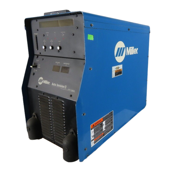
Miller Electric Welder Manuals
Manuals and User Guides for Miller Electric Welder. We have
1
Miller Electric Welder manual available for free PDF download: Owner's Manual
Miller Electric Welder Owner's Manual (132 pages)
Operating Instructions and Programming Instructions
Brand:
Miller Electric
| Category:
Welding System
| Size: 3.75 MB
Table of Contents
Table of Contents
3
Section 1 - Safety Precautions - Read before Using
7
Symbol Usage
7
Arc Welding Hazards
7
Additional Symbols for Installation, Operation, and Maintenance
9
Principal Safety Standards
9
EMF Information
10
Section 1 - Consignes de Securite - Lire Avant Utilisation
11
Signification des Symboles
11
Dangers Relatifs Au Soudage À L'arc
11
Dangers Supplémentaires en Relation Avec L'installation, Le Fonctionnement
13
Et la Maintenance
13
Principales Normes de Sécurité
14
Information Sur Les Champs Électromagnétiques
14
Section 2 - Definitions
15
Manufacturer's Warning Label Definitions
15
Symbols and Definitions
17
Manufacturer's Rating Label
17
Harmonic Data
17
Section 3 - Installation
18
Specifications
18
Dimensions and Weight
18
Selecting a Location
19
Connection Diagram
19
Weld Output Terminals and Selecting Cable Sizes
20
Volts AC Duplex Receptacle and Circuit Breakers
20
Electrical Service Guide
21
Connecting Input Power
21
Rear Panel Connections
22
Peripheral Receptacle Functions
23
Touch Sensor Operation
24
Touch Sensor Board PC18 Switch S1 Settings
24
Connecting Setup Pendant to Welding Power Source
25
Section 4 - Operation
26
Operational Terms
26
Lower Front Panel Controls
27
Meter Functions
27
Upper Front Panel Controls
28
Duty Cycle and Overheating
29
Volt-Ampere Curves
29
Setup Pendant Controls
30
Section 5 - Maintenance & Troubleshooting
31
Routine Maintenance
31
Blowing out Inside of Unit
31
Removing Case and Measuring Input Capacitor Voltage
32
Voltmeter/Ammeter Help Displays
33
Front Panel Error Displays
34
Weld Interface Board PC12 Diagnostic Led's
35
Diagnostic Led's on Weld Interface Board PC12
36
Customer Interface Board PC14 Diagnostic Led's
37
Diagnostic Led's on Customer Interface Board PC14
38
Motor Board PC13 Diagnostic Led's
39
Diagnostic Led's on Motor Board PC13
40
Troubleshooting
40
Section 6 - Electrical Diagrams
42
Section 7 - Parts List
76
Section 8 - Introduction to Programming
82
Pulse MIG Programs
82
Standard Pulse Welding Programs
82
Program 1 - 1.2 MM Steel (.045"), 98-2 Argon-Oxy
83
Program 2 - 1.0 MM Steel (.040"), 80-20 Argon-CO2
83
Program 3 - 1.2 MM Steel (.045"), 80-20 Argon-CO2
84
Program 4 - .8 MM 316 (.030"), 98-2 Argon-CO2
84
Program 5 - 1.0 MM 316 (.040"), 98-2 Argon-CO2
85
Program 6 - 1.2 MM 316 (.045"), 98-2 Argon-CO2
85
Program 7 - 1.0 MM 308L (.040"), 98-2 Argon-CO2
86
Program 8 - 1.2 MM 308L (.045"), 98-2 Argon-CO2
86
Program 1 - 1.2 MM Metal Core (.045"), 95-5 Argon-CO2
87
Program 2 - 1.4 MM Metal Core (.052"), 95-5 Argon-CO2
87
Program 3 - 1.2 MM er 4043 (.045"), Argon
88
Program 4 - 1.0 MM er 4043 (.040"), Argon
88
Program 5 - 1.0 MM 5356 (.040"), Argon
89
Program 6 - 1.2 MM er 5356 (.045"), Argon
89
Program 7 - .8 MM Steel (.030"), 98-2 Argon-Oxy
90
Program 8 - 1.0 MM Steel (.040"), 98-2 Argon-Oxy
90
Setup Pendant Mode Select Button
91
Setup Pendant Parameter Select Button
92
Setup Pendant Parameter Increase and Decrease Buttons
93
Section 9 - Getting Started for Pulse Welding
94
Weld Cycle for Pulse Welding
94
Setting Preflow Sequence Display
94
Setting Weld Sequence Display
95
Setting Crater Sequence Display
95
Setting Postflow Sequence Display
96
Section 10 - Teaching a Pulse Welding Program
96
Pulse Waveform Explained
96
Teach Points Explained
97
Selecting Teach Point Wire Feed Speed for Pulse Welding Program
98
Setting Teach Point Parameters for Pulse Welding Program
99
Changing to Adaptive Pulse Welding
101
Section 11 - Teaching a Mig Welding Program
101
Weld Cycle for Mig Welding
101
Changing to Mig Welding
102
Setting Preflow Sequence Display
102
Setting Start Sequence Display
103
Setting Weld Sequence Display
103
Setting Crater Sequence Display
104
Setting Retract Sequence Display
104
Setting Postflow Sequence Display
105
Setting Run-In Sequence Display
105
SECTION 12 - SETTING Sharparce CONTROL
106
Selecting and Adjusting Sharparce Control
106
Section 13 - Using the Optional Data Card
107
Installing Data Card
107
Using the Data Card
108
Naming Programs and Writing to Card
109
Reading from Card
110
Reading (or Deleting) from an Empty Card
111
Deleting Programs from Card
111
Selecting Security Lock
112
Section 14 - Setup
113
Setup Flow Chart
113
Using Setup Displays
114
Selecting or Changing Access Code
115
Selecting Voltage Correction
116
Selecting Auxiliary Output
116
Selecting Voltage Sensing Method
116
Selecting Arc Start Method
117
Resetting Arc Time
117
Selecting Units for Wire Feed Speed and Motor Type
118
Selecting Wire Type
119
Defining Display Value
119
Resetting Memory
120
Selecting Arc Start/Volt Sense Error Shutdown
120
Selecting Program Name Feature
121
Remote Program Select
121
Remote Program Setting
121
Jog Wire Feed Speed Selection
122
Flow Selection
122
Arc Voltage Error Selection
123
Stick Check Selection
123
Setting Ramps Function
124
Software Version Number
124
Exiting the Setup Menu
124
Section 15 - Control Menu
125
Using Menu Display
125
Setting Rise Time Parameter
126
Setting Adaptive Parameters
126
Setting Auto Configure Parameter
127
Setting Retract On/Off
128
Setting Sharp Start On/Off
128
Exiting the Control Menu
129
Options and Accessories
132
Advertisement
Advertisement
Related Products
Miller Electric Weld Oscillator
Miller Electric WD-5
Miller Electric WC-24
Miller Electric WC-115A
Miller Electric wire feeder
Miller Electric 1/8 WIRE
Miller Electric Categories
Welding System
Welding Accessories
Inverter
Utility Vehicle
Controller
More Miller Electric Manuals
Login
Sign In
OR
Sign in with Facebook
Sign in with Google
Upload manual
Upload from disk
Upload from URL