Sign In
Upload
Manuals
Brands
Garmin Manuals
GPS
GDU 37X
Garmin GDU 37X Manuals
Manuals and User Guides for Garmin GDU 37X. We have
4
Garmin GDU 37X manuals available for free PDF download: Pilot's Manual, Installation Manual
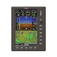
Garmin GDU 37X Pilot's Manual (262 pages)
Multi Function Display
Brand:
Garmin
| Category:
GPS
| Size: 10.71 MB
Table of Contents
Table of Contents
15
Section 1 Overview
19
Unit Overview
19
External Navigator (Optional)
20
GDU 37X Controls
21
System Power-Up
23
Accessing System Functionality
24
Menus
24
Data Entry
25
Main Pages
28
Softkey Function
32
Map Page Softkeys
33
Waypoint Page Softkeys
34
Info Page Softkey
36
Accessing the Information (INFO) Page
37
Acquiring Satellites
38
Entering a New Location
38
New Location
38
Position
39
Data Fields and Layout (Info Page)
41
System Settings
42
Data Bar Fields
43
Display
44
Adjusting the Color Mode
45
Sound
47
Units
47
Date & Time
48
Position
48
Alarms
49
Setting Airport Criteria
50
Section 2 Gps Navigation
53
Introduction
53
Compass Arc
53
Panel
54
Gps Navigation
55
Changing the CDI Scale
56
Setting the Bug Indicator
56
Manually Setting a Course
57
Vertical Navigation (VNAV)
58
Using the VNAV Feature
59
Using Map Displays
61
Map Orientation
62
Map Range
63
Map Panning
64
Panning the Map
65
Measuring Bearing and Distance
66
Topography
67
Satellite View
68
Map Symbols
69
Airports & Navaids
70
Table of Contents
71
Cities & Roads
71
Airspace
72
Airways
73
Displaying/Removing Airways
74
Reviewing Information for an Airway
75
Waypoints
76
Selecting a Runway
79
Nearest Information
81
Weather Information (Optional)
83
Intersections
84
Ndbs
85
User Waypoints
86
Vors
86
Creating User Waypoints
87
Deleting User Waypoints
90
Airspace
91
Airspace Alert Messages
91
Direct-To Navigation
93
Section 3 Flight Planning
97
Introduction
97
Flight Plan Data Fields
97
Manually Switching between Internal and External Flight Plan Sources
98
Failure of the External GPS Navigation Source
99
Flight Plan Creation
100
Flight Planning
101
Flight Plan Storage
103
Flight Plan Activation
105
Adding Waypoints to an Existing Flight Plan
106
Editing Speed, Fuel Flow, and Flight Plan Name
108
Copying Flight Plans
110
Deleting Flight Plans
111
Inverting a Flight Plan
113
Importing/Exporting Flight Plans
113
Approaches (Without External Navigator Configured)
114
Selecting an Approach
115
Activating Vectors-To-Final
118
Trip Planning
119
Section 4 Hazard Avoidance
121
Weather Information
121
S Irius XM Weather (Optional) (GDU 375 Only)
121
Weather Source
122
Activating Services
123
Siriusxm Weather Products
123
Hazard Avoidance
124
Winds Aloft
127
Storm Cells
128
Freezing Levels
132
Using Siriusxm Weather Products
135
Data Link Weather (FIS-B) (370 or 375)
140
Nexrad Abnormalities
144
Terrain
158
Terrain Information
159
Obstacle Information
159
Terrain and Obstacle Color Code
160
Terrain Alerts & Setup
160
Terrain Alerts
162
Traffic Systems
164
Traffic Information Service (TIS-A) (Optional)
165
Disabling Traffic Alerts
167
Traffic Warning Window
168
Traffic Ground Track
168
Data Link Traffic (GDL 39) (GDU 370 or 375)
169
System Status
172
Traffic Description
173
Symbol Description
173
Displaying Traffic Data
176
Section 5 Additional Features
181
Safetaxi
182
Safetaxi Cycle Number and Revision
183
Chartview (Optional)
184
Aircraft Symbol
185
Chart Range
186
Jeppesen Database-Published Notams
187
Flitecharts
188
Additional Features
189
Chart Range
190
Flitecharts ® Cycle Number and Expiration Date
190
Airport Directory DATA
191
Siriusxm Radio Entertainment (GDU 375)
193
Activating Siriusxm Satellite Radio Services
193
Using Siriusxm Radio
194
Selecting a Category
195
Selecting a Channel
196
Using Favorites
197
Adjusting the Volume
198
Electronic Checklists
199
Flight Data Logging
199
Section 6 Appendices
201
Messages, Alerts & Data Field Options
201
System Status Messages (Info Page)
201
Aural Alerts
202
Airspace Messages
204
Data Bar Field Options
205
Abnormal Operation
209
Loss of GPS Position
209
Hazard Display with Loss of GPS Position
209
SD Card Use and Databases
211
Installing and Removing SD Cards
211
GDU 37X Databases
212
Navigation Database
213
Updating GDU 37X Databases
215
Exporting Track Logs and User Waypoints
218
Importing/Exporting Flight Plans
218
General TIS-A Information
221
TIS-A Vs. TAS/TCAS
221
TIS-A Limitations
221
Table of Contents
225
Utilities
225
Flight Log
225
Track Log
227
Changing Track Log Settings
228
Heading Line
229
E6B Calculator
231
Weight & Balance
233
EPE Circle
235
Proximity Waypoints
236
Deleting Proximity Waypoints
237
Display Symbols
239
VFR Symbols
239
IFR Symbols
240
Airspace Symbols
242
Map Datum and Location Formats
245
Map Datums
245
Location Formats
245
Glossary
247
License Agreement and Warranty
253
Contact Garmin
253
Software License Agreement
253
Limited Warranty
253
Siriusxm Satellite Radio Service Agreement
254
AOPA Airport Directory Notice
254
Ac-U-Kwik License Agreement
255
Weather Data Warranty
255
Index
260
Advertisement
Garmin GDU 37X Installation Manual (188 pages)
Garmin GPS Receiver Installation Manual
Brand:
Garmin
| Category:
GPS
| Size: 7.01 MB
Table of Contents
Installation Manual
1
Table of Contents
4
Paragraph Page
5
1 G3X Installation Overview
15
Unpacking Unit
15
Introduction
15
System Overview
16
G3X Interconnect Example
16
General G3X LRU Specifications
17
Installation Requirements
19
Mounting
19
Wiring/Cabling Considerations
19
Coaxial Cable Installation
21
Section 1 1-1 –
22
2 Gdu 37X
23
Equipment Description
23
GDU 37X Unit View
23
Electrical Specifications
24
Environmental Specifications
25
GDU 37X Mounting Accessories
26
Installation Requirements
26
Installation Considerations
27
Mounting Requirements
27
Unit Installation
27
Maintenance
27
Section 2 2-1 –
28
Panel Cutout Template
28
3 Gmu 44
29
Equipment Description
29
Electrical Specifications
29
Environmental Specifications
30
GMU 44 TSO/ETSO Compliance
30
Installation Requirements
31
Installation Considerations
31
GSU 73/GMU 44 Interconnect Harness Fabrication Instructions
33
Maintenance
34
Section 3 3-1 –
34
Mounting Instructions
34
5 Gtp 59
35
GSU 73 Unit View
35
Equipment Description
35
Electrical Specifications
36
Installation Requirements
37
Installation Considerations
38
GSU 73 Air Hose Fitting Locations
39
Mounting Requirements
40
GSU 73 Orientation Calibration
40
Unit Installation
41
G3X LRU Part Numbers
42
Contents of GDU 37X Assembly (010-00667-XX)
42
G3X LRU Power Requirements
42
G3X LRU Physical Specifications
42
Contents of G3X Installation Kit (K10-00017-00)
42
Contents of G3X LRU Kit (K10-00016-00)
42
Pin Contact and Crimp Tools Part Numbers
42
Section 4 4-1 –
42
Maintenance
42
GDU 37X Supply Voltages
43
GDU 37X Power Requirements
43
GDU 37X GPS Specifications
43
GDU 37X Supported Antennas
43
Contents of GDU 37X Connector Kit (011-01921-00)
43
Equipment Description
43
Installation Requirements
43
TSO/ETSO Compliance
44
GMU 44 Electrical Specifications
44
GMU 44 Environmental Specifications
44
TSO/ETSO Deviations
44
GMU 44 Part Numbers
44
GMU 44 Accessories
44
Required Distance from Magnetic Disturbances
44
Parts Needed for GMU 44 Installation
44
GMU 44 Connector Kit (011-00871-00) Contents, Reference Figure C-2.4
44
TSO/ETSO Deviations for the GTP 59
44
Installation Considerations
45
GSU 73 Supply Specifications
45
GSU 73 Environmental Specifications
45
GSU 73 Available Equipment
45
Contents of P731 Connector Kit (011-01818-00)
45
Contents of P732 Connector Kit (011-01818-01)
45
Section 5 5-1 –
46
Unit Installation
46
Maintenance
46
GTP 59 Part Number
46
GTP 59 Outside Air Temperature Kit
46
Applicable Tso/Etsos for the GTP 59
46
Parts Needed for GTP 59 Installation
46
6 Garmin GPS/XM Antennas
47
GPS Antennas
47
XM Antennas
47
GPS Antenna Minimum Requirements
47
Antenna Mounting Considerations
48
XM Satellite Radio Antenna Minimum Requirements
48
Recommended Antenna Placement
50
Carbon/Glass Buried Antenna Area
51
Glare Shield Buried Antenna Area
52
Teardrop Footprint Antenna Installation (GA 55 and GA 56)
53
Teardrop Footprint Antenna Doubler Design and Installation
53
Antenna Installation Instructions
54
Doubler Design, Teardrop Footprint Antenna, Skin Thickness 0.051" to 0.063"
56
Sample Doubler Location, Teardrop Footprint Antenna, Metal Skin Aircraft
56
ARINC 743 Footprint Antenna Installation (GA 55A, GA 57X)
60
ARINC 743 Footprint Antenna Doubler Design and Installation
60
Doubler Design, ARINC 743 Footprint Antenna, Skin Thickness 0.032" to 0.049"
62
Doubler Design, ARINC 743 Footprint Antenna, Skin Thickness 0.049" to 0.051"
63
Doubler Design, ARINC 743 Footprint Antenna, Skin Thickness 0.051" to 0.063"
64
Sample Doubler Location, ARINC 743 Antenna, Metal Skin Aircraft
65
Installation of ARINC 743 Footprint Antenna
68
Non-Structural Mount Installation
69
Generic Non-Structural ARINC 743 Footprint Antenna Installation
69
Example Bracket Antenna Mounting under Glareshield
70
Example Non-Structural Antenna Mounting under Glareshield
71
Example Teardrop Antenna Installation in Airframe under Fabric Skin
72
Example ARINC 743 Footprint in Airframe under Fabric Skin
72
Example Non-Structural Antenna Mounting on Airframe
73
Section 6 6-1 –
74
Example Teardrop Footprint Antenna Mounting under Fabric Skin
74
Minimum Distance Required between Tube Structure and Antenna
74
7 Software, Configuration, Databases, and XM Activation
75
Configuration Mode
75
Software/Audio Data Identification
75
Software Loading Procedure
77
Configuration
78
Acft Configuration Page
79
Units Configuration Page
81
Sound Configuration Page
84
Comm Configuration Page
85
Garmin Database Updates
86
Available Databases
87
Section 7 7-1 –
88
XM Activation Instructions (GDU 375 Only)
88
8 Post-Installation Checkout and Calibration Procedures
89
Softkey Positions
89
Recommended Test Equipment
90
GDU 37X Test Procedure
90
GSU 73/GMU 44 Post-Installation Calibration Procedure
92
Post-Installation Calibration Procedure Summary
92
Data Validity Requirements for AHRS Calibration Procedures
93
Configuration Mode GSU Page Status Boxes
93
Aircraft Alignment
98
Magnetometer Interference Test Sequence Example
111
Section 8 8-1 –
114
9 Troubleshooting
115
Gdu 37X
115
Gmu 44
116
Heading Failure Indication (Full-Screen PFD)
116
Gsu 73
117
GSU 73 AHRS Pitch/Bank Limitations for Cold Start While Airborne
117
Attitude, Air Data, and Engine/Airframe Failure Indication
119
AHRS Align Message (PFD)
120
GSU 73 -Air Data Troubleshooting
121
Airspeed and Altitude Failure Indications
121
Attitude, Heading, Air Data, and Engine/Airframe Failure
123
Troubleshooting On-Board the Aircraft
124
GSU Page
125
CONFIG GSU Page
125
Section 9 9-1 –
126
10 Return to Service Information
127
Gdu 37X
127
Gsu 73
127
Gmu 44
128
Section 10 10-1 –
128
APPENDIX A G3X Pinouts
129
Gdu 37X
129
A-1 View of J3701 Connector from Back of Unit
129
Gmu 44
133
A-2 View of J441 Connector Looking at Rear of Unit
133
Gsu 73
134
A-3 Rear View of Connector End Plate
134
APPENDIX B Connector Installation Instructions
145
Thermocouple Installation into a Backshell
145
B-1 Insulation/Contact Clearance
145
B-1 Thermocouple Kit GPN 011-00981-00
145
B-2 Jackscrew Backshell Thermocouple Installation
146
Jackscrew Configuration Module Installation into a Jackscrew Backshell
147
B-2 GPN: 011-00979-20 – Kit (W/Eeprom and Pins)
147
B-3 GPN: 011-00979-22 – Kit (W/Eeprom and Sockets)
147
B-3 Insulation/Contact Clearance
148
B-4 Jackscrew Backshell Installation
149
Jackscrew Backshell Installation Instructions
150
B-4 Parts Supplied for a Shield Block Installation (Figure B-1)
150
B-5 Parts NOT Supplied for a Shield Block Installation (Figure B-1)
150
B-5 Shield Install Onto a Jackscrew Backshell (78 Pin Example)
151
B-6 Method A.1 for Shield Termination
152
B-6 Shielded Cable Preparations for Garmin Connectors
152
B-7 Insulation/Contact Clearance
154
B-8 Method A.2 (Daisy Chain) for Shield Termination
156
B-9 Method B.1 (Quick Term) for Shield Termination
157
B-10 Method B.2 (Daisy Chain-Quick Term) for Shield Termination
158
B-7 Shielded Cable Preparations – (Quick Term)
158
B-11 Daisy Chain between Methods a and B
159
B-12 Method C.1 Double-Shield Termination
160
B-8 Shielded Cable Preparations for Garmin Connectors
160
B-13 Method C.2 Double-Shield Termination
161
B-14 D-Sub Spliced Signal Wire Illustration
162
Circular Connector Installation Instructions
163
B-9 Parts Supplied for a Circular Connector Installation (Figure B-15)
163
B-10 Parts NOT Supplied for a Circular Connector Installation (Figure B-15)
163
B-15 Circular Connector Install (19 Contact Example)
164
B-16 Standard Shield Termination
164
B-11 Shielded Cable Preparations for Garmin Connectors
165
B-17 Insulation/Contact Clearance
167
B-18 Daisy Chain Shield Termination
168
B-19 Quick Term Shield Termination
169
B-12 Shielded Cable Preparations – (Quick Term)
169
B-20 Daisy Chain, Quick-Term Shield Termination
171
B-21 Daisy Chain Shield Termination between Methods a and B
172
Appendix C Outline and Installation Drawings
173
C-1.1 GDU 37X Outline Drawing
173
C-1.2 GDU 37X Panel Cutout Drawing
174
C-2.1 GMU 44 Mounting Rack
175
C-2.3 GMU 44 Bottom Mounted Installation
177
C-2.4 GMU 44 Wiring Detail
178
C-3.1 GSU 73 Outline Drawing
179
C-4.1 GTP 59 O.A.T. Probe Installation Drawing
180
C-5.1 GA 55/55A Installation Drawing
181
C-5.2 GA 56 Installation Drawing
182
Appendix D Interconnect Drawing
184
APPENDIX E: External Interface Drawing (Example Only
186
E-1.1 Notes, GDU 37X RS-232 and Audio Examples
186
E-1.2 GSU 73 RS-232 and ARINC 429 Examples
187
Garmin GDU 37X Installation Manual (90 pages)
Brand:
Garmin
| Category:
GPS
| Size: 6.28 MB
Table of Contents
Installation Manual
1
Table of Contents
4
Paragraph Page
5
Limited Warranty
10
Section 1 GDU 37X Installation Overview
11
Unpacking Unit
11
Introduction
11
System Overview
11
Section 1 GDU 37X Installation Overview
12
General GDU 37X LRU Specifications
12
Garmin LRU Part Numbers
12
Power Specifications
12
Physical Specifications
12
GDU 37X LRU Part Numbers
12
Contents of GDU 37X Assembly (010-00667-XX)
12
GDU 37X LRU Power Requirements
12
GDU 37X LRU Physical Specifications
12
Cooling Requirements
13
Mounting
13
Wiring/Cabling Considerations
13
Wiring Harness Installation
13
Cable Location Considerations
14
Pin Contact and Crimp Tools Part Numbers
14
Cable Installation
15
Backshell Assemblies
15
Coax Cable Installation
15
Section 2 GDU 37X
17
Equipment Description
17
Navigation Functions
17
Interface Summary
17
Section 2 GDU 37X
18
Electrical Specifications
18
Electrical Characteristics
18
Power Consumption
18
GPS Specifications
18
GDU 37X Supply Voltages
18
GDU 37X Power Requirements
18
GDU 37X GPS Specifications
18
Antennas
19
Environmental Specifications
19
Installation Requirements
20
Required Accessories
20
Additional Equipment Required
20
Section 2 GDU 37X
20
GDU 37X Mounting Accessories
20
Contents of GDU 37X Connector Kit (011-01921-00)*
20
GDU 37X Required Accessories
20
Continued Airworthiness
21
Installation Considerations
21
Mounting Requirements
21
Unit Installation
21
GDU 37X Panel Cutout Template
22
Panel Cutout Template
22
Section 2 2-1 –
22
Section 3 Garmin GPS/XM Antennas
23
Section 3 Garmin GPS/XM Antennas
23
GPS Antennas
23
XM Antennas
23
GPS Antenna Minimum Requirements
23
Antenna Mounting Considerations
24
VHF COM/GPS Interference
24
XM Satellite Radio Antenna Minimum Requirements
24
GPS/XM Antenna Mounting Location
25
Section 3 Garmin GPS/XM Antennas
26
Recommended Antenna Placement
26
Buried Antenna (below the Skin Covering or Glareshield) Mounting
27
Carbon/Glass Buried Antenna Area
27
Antenna Doubler/Backing Plate
28
Antenna Grounding Plane
28
Glare Shield Buried Antenna Area
28
Antenna Grounding
29
Teardrop Footprint Antenna Installation (GA 55 and GA 56)
29
Preparation of Doubler
29
Teardrop Footprint Antenna Doubler Design and Installation
29
Antenna Installation Instructions
30
Reference Figures
30
Paragraph
29
Doubler Design, Teardrop Footprint Antenna, Skin Thickness 0.032" to 0.049"
30
Doubler Design, Teardrop Footprint Antenna, Skin Thickness 0.049" to 0.051"
31
Doubler Design, Teardrop Footprint Antenna, Skin Thickness 0.051" to 0.063"
31
Sample Doubler Location, Teardrop Footprint Antenna, Metal Skin Aircraft
32
Skin Cutout Detail, Teardrop Footprint Antenna, Skin Thickness 0.032" to 0.049"
32
ARINC 743 Footprint Antenna Installation (GA 55A, GA 57X)
35
ARINC 743 Footprint Antenna Doubler Design and Installation
35
Preparation of Doubler
36
Antenna Installation Instructions
36
Reference Figures
37
Doubler Design, ARINC 743 Footprint Antenna, Skin Thickness 0.032" to 0.049"
37
Doubler Design, ARINC 743 Footprint Antenna, Skin Thickness 0.049" to 0.051"
38
Doubler Design, ARINC 743 Footprint Antenna, Skin Thickness 0.051" to 0.063"
39
Sample Doubler Location, ARINC 743 Antenna, Metal Skin Aircraft
40
Skin Cutout Detail, ARINC 743 Footprint Antenna, Skin Thickness 0.032" to 0.049"
40
Doubler Installation, ARINC 743 Footprint, Skin Thickness 0.051" to 0.063"
43
Installation of ARINC 743 Footprint Antenna
43
Non-Structural Mount Installation
44
Generic Non-Structural Antenna Installation
44
Generic Non-Structural ARINC 743 Footprint Antenna Installation
44
Considerations for Non-Structural Mounting
45
Non-Structural Installation to Glareshield
45
Example Bracket Antenna Mounting under Glareshield
45
Example Non-Structural Antenna Mounting under Glareshield
46
Non-Structural Installation to Airframe
47
Example Teardrop Antenna Installation in Airframe under Fabric Skin
47
Example ARINC 743 Footprint in Airframe under Fabric Skin
47
Example Non-Structural Antenna Mounting on Airframe
48
Example Teardrop Footprint Antenna Mounting under Fabric Skin
49
Minimum Distance Required between Tube Structure and Antenna
49
Section 3 3-1 –
50
Section 4 Software, Configuration, Databases, and XM Activation
51
Configuration Mode
51
Software/Audio Data Identification
51
LRU Software and Audio Data Version Identification
51
Software Loading Procedure
52
GDU Software Loading Procedure
52
Configuration
53
Main Configuration Page
53
ACFT Configuration Page
54
W/B (Weight/Balance) Configuration Page
55
UNITS Configuration Page
56
DSPL (Display) Configuration Page
57
SOUND Configuration Page
59
COMM Configuration Page
60
Garmin Database Updates
61
Updating Garmin Databases
61
Available Databases
63
Section 4 4-1 –
64
XM Activation Instructions (GDU 375 Only)
64
Section 5 Post-Installation Checkout Procedure
65
Required Test Equipment
65
GDU 37X Test Procedure
65
Section 5 5-1 –
66
Appendix A GDU 37X Pinouts
67
Appendix A GDU 37X Pinouts
67
Gdu 37X
67
P3701 Connector
67
View of J3701 Connector from Back of Unit
67
Aircraft Power
68
Demo Mode Selection
68
Serial Data
69
Lighting
69
Audio
69
Appendix B Connector Installation Instructions
71
Paragraph
71
Appendix B Connector Installation Instructions
71
Jackscrew Backshell Installation Instructions
71
Shield Block Installation Parts
71
Parts Supplied for a Shield Block Installation (Figure B-1)
71
Parts Not Supplied for a Shield Block Installation (Figure B-1)
71
Appendix B Connector Installation Instructions
72
Shield Install Onto a Jackscrew Backshell (78 Pin Example)
72
Shield Termination Technique - Method A.1 (Standard
73
Method A.1 for Shield Termination
73
Shielded Cable Preparations for Garmin Connectors
73
Insulation/Contact Clearance
75
Shield Termination Technique - Method A.2 (Daisy Chain
77
Method A.2 (Daisy Chain) for Shield Termination
77
Shield Termination - Method B.1 (Quick Term
78
Method B.1 (Quick Term) for Shield Termination
79
Shielded Cable Preparations – (Quick Term)
79
Method B.2 (Daisy Chain-Quick Term) for Shield Termination
80
Shield Termination-Method B.2 (Daisy Chain-Quick Term
80
Daisy Chain between Methods a and B
81
Double-Shield Termination Technique - Method
82
Method C.1 Double-Shield Termination
82
Shielded Cable Preparations for Garmin Connectors
82
Double-Shield Termination Technique (Quick Term) - Method
83
ID Program Pins (Strapping
83
Method C.2 Double-Shield Termination
83
Splicing Signal Wires
84
D-Sub Spliced Signal Wire Illustration
84
Appendix C Outline and Installation Drawings
85
GDU 37X Outline Drawing
85
GDU Panel Cutout Drawing
86
GA 55/55A Installation Drawing
87
GA 56 Installation Drawing
88
GA 57X Installation Drawing
89
Appendix D Interconnect Drawing (Example Only)
90
GDU 37X Interconnect Drawing
90
Advertisement
Garmin GDU 37X Installation Manual (93 pages)
Brand:
Garmin
| Category:
GPS
| Size: 10.18 MB
Table of Contents
Installation Manual
1
Aviation Limited Warranty
5
Table of Contents
6
Paragraph Page
7
Figure
11
Section 1 GDU 37X Installation Overview
11
System Overview
12
General GDU 37X LRU Specifications
12
Table 1-1 GDU 37X LRU Part Numbers
12
Table 1-2 Contents of GDU 37X Assembly (010-00667-XX)
12
Table 1-3 GDU 37X LRU Power Requirements
13
Table 1-4 GDU 37X LRU Physical Specifications
13
Mounting
14
Wiring/Cabling Considerations
14
Table 1-5 Pin Contact and Crimp Tools Part Numbers
14
Figure 1-1. TNC Connector Installation
16
GDU 37X Installation Overview
11
Unpacking Unit
11
Introduction
11
Section 1 GDU 37X Installation Overview
12
Table
12
Section 2 GDU 37X
17
Figure 2-1. GDU 37X
17
Electrical Specifications
18
Table 2-1 GDU 37X Supply Voltages
18
Table 2-2 GDU 37X Power Requirements
18
Table 2-3 GDU 37X GPS Specifications
18
Table 2-4 GDU 37X Supported Antennas
19
Environmental Specifications
20
Installation Requirements
20
Table 2-5 GDU 37X Required Accessories
20
Table 2-6 Contents of GDU 37X Connector Kit (011-01921-00)*
20
Figure 2-2. GDU 37X Mounting Accessories
21
Installation Considerations
22
Mounting Requirements
22
Unit Installation
22
Continued Airworthiness
22
Figure 2-3. GDU 37X Panel Cutout Template
23
Gdu 37X
17
Equipment Description
17
Section 2 GDU 37X
18
Section 3 Garmin GPS/XM Antennas
24
Section 3 Garmin GPS/XM Antennas
24
Table 3-2 GPS Antenna Minimum Requirements
24
XM Antennas
25
Antenna Mounting Considerations
25
Table 3-3 XM Antennas
25
Table 3-4 XM Satellite Radio Antenna Minimum Requirements
25
Figure 3-1. Recommended Antenna Placement
28
Figure 3-2. Carbon/Glass Buried Antenna Area
29
Figure 3-3. Glare Shield Buried Antenna Area
30
Teardrop Footprint Antenna Installation (GA 55 and GA 56)
31
1" to 0.063
31
Table 3-5 Teardrop Footprint Antenna Doubler Design and Installation
31
Figure 3-4. Doubler Design, Teardrop Footprint Antenna, Skin Thickness
32
Figure 3-5. Doubler Design, Teardrop Footprint Antenna, Skin Thickness 0.049" to 0.051
33
Figure 3-6. Doubler Design, Teardrop Footprint Antenna, Skin Thickness 0.051" to 0.063
33
Figure 3-7. Sample Doubler Location, Teardrop Footprint Antenna, Metal Skin Aircraft
34
Figure 3-8. Skin Cutout Detail, Teardrop Footprint Antenna, Skin Thickness 0.032" to 0.049
34
Figure 3-9. Skin Cutout Detail, Teardrop Footprint Antenna, Skin Thickness 0.049" to 0.051
35
Figure 3-10. Skin Cutout Detail, Teardrop Footprint Antenna, Skin Thickness 0.051" to 0.063
35
Figure 3-11. Doubler Installation, Teardrop Footprint Antenna, Skin Thickness 0.032" to 0.049
36
Figure 3-12. Doubler Installation, Teardrop Footprint Antenna, Skin Thickness 0.049" to 0.051
36
ARINC 743 Footprint Antenna Installation (GA 55A, GA 57X)
37
Figure 3-13. Doubler Installation, Teardrop Footprint Antenna, Skin Thickness
37
Table 3-6 ARINC 743 Footprint Antenna Doubler Design and Installation
37
Figure 3-14. Doubler Design, ARINC 743 Footprint Antenna, Skin Thickness 0.032" to 0.049
39
Figure 3-15. Doubler Design, ARINC 743 Footprint Antenna, Skin Thickness 0.049" to 0.051
40
Figure 3-16. Doubler Design, ARINC 743 Footprint Antenna, Skin Thickness 0.051" to 0.063
41
Figure 3-17. Sample Doubler Location, ARINC 743 Antenna, Metal Skin Aircraft
42
Figure 3-18. Skin Cutout Detail, ARINC 743 Footprint Antenna, Skin Thickness 0.032" to 0.049
42
Figure 3-19. Skin Cutout Detail, ARINC 743 Footprint Antenna, Skin Thickness 0.049" to 0.051
43
Figure 3-20. Skin Cutout Detail, ARINC 743 Footprint Antenna, Skin Thickness
43
Figure 3-21. Doubler Installation, ARINC 743 Footprint Antenna, Skin Thickness 0.032" to 0.049
44
Figure 3-22. Doubler Installation, ARINC 743 Footprint Antenna, Skinthickness 0.049" to 0.051
44
Figure 3-23. Doubler Installation, ARINC 743 Footprint, Skin Thickness 0.051" to 0.063
45
Figure 3-24. Installation of ARINC 743 Footprint Antenna
45
Non-Structural Mount Installation
46
Figure 3-25. Generic Non-Structural ARINC 743 Footprint Antenna Installation
46
Figure 3-26. Example Bracket Antenna Mounting under Glareshield
47
Figure 3-27. Example Non-Structural Antenna Mounting under Glareshield
48
Figure 3-28. Example Teardrop Antenna Installation in Airframe under Fabric Skin
49
Figure 3-29. Example ARINC 743 Footprint in Airframe under Fabric Skin
49
Figure 3-30. Example Non-Structural Antenna Mounting on Airframe
50
Figure 3-31. Example Teardrop Footprint Antenna Mounting under Fabric Skin
51
Table 3-7 Minimum Distance Required between Tube Structure and Antenna
51
Garmin GPS/XM Antennas
24
GPS Antennas
24
Section 4 Software, Configuration, Databases, and XM Activation
52
Software Loading Procedure
53
Configuration
54
Acft Configuration Page
55
Comm Configuration Page
61
Garmin Database Updates
62
Available Databases
64
Siriusxm® Activation Instructions (GDU 375 Only)
65
GDL 39/GDL 39R Software Update
66
Software, Configuration, Databases, and XM Activation
52
Configuration Mode
52
Software/Audio Data Identification
52
Section 5 Post-Installation Checkout Procedure
67
Post-Installation Checkout Procedure
67
Required Test Equipment
67
GDU 37X Test Procedure
67
Appendix A GDU 37X Pinouts
69
Section 5 Post-Installation Checkout Procedure
69
Appendix A GDU 37X Pinouts
69
Gdu 37X
69
Figure A-1 View of J3701 Connector from Back of Unit
69
Table A-1 J3701
69
Table A-2 Aircraft Power
71
Table A-3 Demo Mode
71
Table A-4 RS-232
71
Table A-5 Lighting
72
Table A-6 Mono Audio
72
Table A-7 Stereo Audio
72
Appendix B Connector Installation Instructions
73
Paragraph
73
Appendix B Connector Installation Instructions
73
Jackscrew Backshell Installation Instructions
73
Table B-1 Parts Supplied for a Shield Block Installation (Figure
73
Table B-2 Parts Not Supplied for a Shield Block Installation (Figure
73
Figure B-1 Shield Install Onto a Jackscrew Backshell (78 Pin Example
74
Figure B-2 Method A.1 for Shield Termination
75
Table B-3 Shielded Cable Preparations for Garmin Connectors
75
Figure B-3 Insulation/Contact Clearance
77
Figure B-4 Method A.2 (Daisy Chain) for Shield Termination
79
Figure B-5 Method B.1 (Quick Term) for Shield Termination
81
Table B-4 Shielded Cable Preparations - (Quick Term
81
Figure B-6 Method B.2 (Daisy Chain-Quick Term) for Shield Termination
82
Figure B-7 Daisy Chain between Methods a and B
83
Figure B-8 Method C.1 Double-Shield Termination
84
Table B-5 Shielded Cable Preparations for Garmin Connectors
84
Figure B-9 Method C.2 Double-Shield Termination
85
Figure B-10 D-Sub Spliced Signal Wire Illustration
86
Appendix C Outline and Installation Drawings
87
Figure C-1.1 GDU 37X Outline Drawing
87
Appendix C Outline and Installation Drawings
88
Figure C-1.2 GDU 37X Panel Cutout Drawing
88
Figure C-2.1 GA 55/55A Installation Drawing
89
Figure C-2.2 GA 56 Installation Drawing
90
Figure C-2.3 GA 57X Installation Drawing
91
Appendix D Interconnect Drawing (Example Only
92
Figure D-1.1 GDU 37X Interconnect Drawing
92
Appendix D Interconnect Drawing (Example Only
93
Figure D-1.2 GDU 37X Interconnect Drawing
93
190-01054-01 GDU 37X Installation Manual
93
Advertisement
Related Products
Garmin GDU 375
Garmin GDU 370
Garmin GDU 620
Garmin GDL 88 with GPS/SBAS
Garmin GDL 88D with GPS/SBAS
Garmin GDL 88D
Garmin GDL 39
Garmin GPS 400
Garmin GPS 120
Garmin GPS 90
Garmin Categories
GPS
Watch
Car Navigation system
Avionics Display
Marine GPS System
More Garmin Manuals
Login
Sign In
OR
Sign in with Facebook
Sign in with Google
Upload manual
Upload from disk
Upload from URL