Sign In
Upload
Manuals
Brands
Delta Manuals
Controller
DVP-20PM
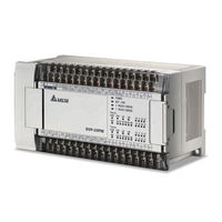
Delta DVP-20PM Manuals
Manuals and User Guides for Delta DVP-20PM. We have
3
Delta DVP-20PM manuals available for free PDF download: Applications Manual, Instruction Sheet
Delta DVP-20PM Applications Manual (580 pages)
Brand:
Delta
| Category:
Controller
| Size: 14.13 MB
Table of Contents
Dvp-20Pm Application Manual
2
Table of Contents
2
Chapter 1 Program Framework of a DVP-PM Series Motion Controller
9
Structure of O100
9
Manual Function of O100
10
Structure of Ox Motion Subroutines
11
Structure of P Subroutines
12
Using O100, Ox Motion Subroutines, and P Subroutines
14
Structure of a Program
14
Chapter 2 Hardware Specifications and Wiring
17
Hardware Specifications
17
Electrical Specifications for Input Terminals/Output Terminals
17
Specifications for Power
17
Dimensions
20
Wiring
22
Installation of a DVP-20PM Series Motion Controller in a Control Box
23
Wiring Power Input
23
Safety Wiring
24
Wiring Input/Output Terminals
24
Wiring a DVP-20PM Series Motion Controller and an Inferior Servo Drive
30
Communication Ports
35
COM1 (RS-232 Port)
35
COM2 (RS-485 Port)
36
COM3 (RS-232/RS-485 Port)
36
Chapter 3 Devices
37
Device Lists
37
Values, Constants, and Floating-Point Numbers
40
External Input Devices and External Output Devices
42
Auxiliary Relays
44
Stepping Relays
44
Timers
44
Counters
45
Registers
49
Specail Auxiliary Relays and Special Data Registers
49
Index Registers
50
Functions of Special Auxiliary Relays and Special Data Registers
66
Special Data Registers for Motion Axes
82
Descriptions of the Special Data Registers Related to Motion
83
Introduction of Modes of Motion
100
Special Data Registers for Motion Axes
101
Chapter 4 Basic Instructions
105
Table of Basic Instructions
105
Descriptions of the Basic Instructions
107
Chapter 5 Applied Instructions and Basic Usage
121
Table of Applied Instructions
121
Structure of an Applied Instruction
125
Processing Values
127
Instruction Index
130
Using Index Registers to Modify Operands
130
Descriptions of the Applied Instructions
134
(API 110~175) Floating-Point Value
191
(API 215~223) Logical Operation
246
Motion Control Function Block Table
265
Introduction of the Pins in a Motion Control Function Block
266
Definitions of Input Pins/Output Pins
266
Introducing the Use of Pmsoft
268
Timing Diagram for Input/Output Pins
268
Delta-Defined Parameter Table
270
Uniaxial Motion Control Function Blocks
272
Absolute Single-Speed Motion
272
Relative Single-Speed Motion
276
Absolute Two-Speed Motion
280
Relative Two-Speed Motion
283
Inserting Single-Speed Motion
286
Inserting Two-Speed Motion
290
JOG Motion
294
Manual Pulse Generator Mode
297
Electronic Gear Motion
299
Returning Home
301
Setting Input Sources for Manual Pulse Generators/Electronic Gears
303
Stopping Uniaxial Motion
304
Parameter Setting I
306
Parameter Setting II
308
Reading the Present Position/Speed of an Axis
310
State of an Axis
312
Setting the Present Position of an Axis
314
Setting the Polarities of Input Terminals
315
Uniaxial Cyclic Electronic Cam Motion
317
Uniaxial Noncyclic Electronic Cam Motion
322
Multiaxial Cyclic Electronic Cam Motion
326
Reading a Cam Point
330
Writing a Cam Point
332
Calculating a Synchronization Ratio
334
Creating a Cam Curve
337
Updating a Cam Curve
344
Flying Shear
352
Creating a Curve for a Wire Winding Machine
359
Multiaxial Motion Control Function Blocks
363
Setting the Parameters of G-Code Motion
363
Executing G-Code Motion
366
Stopping G-Code Motion
368
Reading an M-Code
370
Other Motion Control Function Blocks
372
High-Speed Counter
372
Setting High-Speed Comparison
375
Resetting High-Speed Comparison
377
Setting High-Speed Capture
380
High-Speed Masking
384
Setting an Interrupt
386
Chapter 6 Basic Usage of Motion Instructions and G-Codes
389
Table of Motion Instructions and Table of G-Codes
389
Composition of a Motion Instruction/G-Code
391
Motion Instruction
391
G-Code Instruction
392
Descriptions of Motion Instructions
395
Descriptions of O Pointers/M-Code Instructions
428
Descriptions of G-Code Instructions
433
Chapter 7 Using a DVP-20PM Series Motion Controller as a Slave
441
Access between DVP-EH2, DVP20PM (as a Master) and DVP-20PM (as a Slave)
441
Example of Master-Slave Data Exchange
441
Structure
441
7 Using a Dvp-20Pm Series Motion Controller as a Slave
445
Chapter 8 Application Examples
447
Drawing Paths by Motoin Instructions and G-Codes
447
Paths
447
Steps
448
Dmov K0 D1848
449
Dmov K0 D1928
449
Ld M1000
449
O100 Ld M1002
449
Applying Application Examples in Pmsoft
452
Program Structure
452
Bret
453
Designing an Example Program
453
Dmov K200000 D1828
453
Dmov K200000 D1908
453
Drv X200000 Fx100000 Y200000 Fy100000 M2
453
Drvz
453
Operation
453
Planning Variable Speed Operation
455
Program Structure
455
Designing Programs
456
Connecting DVP20PM00D (as a Master) and DVP01PU-H2 (as a Slave) for Controlling the Third Axis
457
Chapter 9 Electronic Cam
459
Introduction of Electronic Cams
459
Operation of an Electronic Cam
460
Creating Electronic Cam Data
460
Initial Setting
460
Setting Terminals
460
Setting an Input/Output Pulse Type
461
Setting an Input/Output Ratio
462
Setting a Starting Angle
463
Setting a Master Axis
464
Starting/Stopping a Cyclic Electronic Cam
468
Starting/Stopping an Electronic Cam
468
Starting/Stopping a Noncyclic Electronic Cam
471
Registers for Electronic Cam Motion
473
Creating Electronic Cam Data
477
Creating a Cam Chart in Pmsoft
478
Function Relating the Position of a Master Axis to the Position of a Slave Axis
478
Measuring the Relation between the Position of a Master Axis and the Position of a Slave Axis at Work
481
Using DTO/DFROM to Create Electronic Cam Data
482
Creating/Modifying Electronic Cam Data
488
Current Position of X/Y Axis in O100
488
Creating a Smooth Curve
490
Creating Rotary Cut Data
494
Electronic Cam Data for Cutting Thick Material
499
Offset Compensation for a Slave Error
503
Application of a Flying Shear-Checking the Position of a Cutter
505
Multi-Axis Cam
505
Practical Application of an Electronic Cam
509
Application of a Winfing Machine
509
Operation of a High-Speed Winding Device
510
Wiring Hardware
512
Creating an Electronic Cam Curve
513
Application of a Rotary Cutter
515
Operation of a Rotary Cutter
515
Creating an Electronic Cam Curve
516
Application of a Flying Shear
517
Creating an Electronic Cam Curve
518
Chapter 10 Application of G-Codes
525
Downloading a Program with PEP
525
Methods of Downloading G-Codes
526
PMGDL Software
526
Applying G-Codes to a Dispenser
537
Storing G-Codes/M-Codes
541
Chapter 11 Canopen Communication Card
543
Introduction of DVP-FPMC: Canopen Communication Card
543
Specifications
543
Parameters for Control Registers
544
Product Profile and Installation
544
Descriptions of Control Registers
546
Setting a DVP-FPMC Mode
561
Ethernet Mode of DVP-FPMC
563
Communication between DVP-FPMC and an HMI
564
Communication between DVP-FPMC and Pmsoft
566
LED Indicators and Troubleshooting
569
Chapter 12 High-Speed Comparison and High-Speed Capture
571
High-Speed Comparison and High-Speed Capture
571
High-Speed Comparison
573
High-Speed Capture
576
Appendix A: Error Code Table
579
Chapter 13 Appendix
579
Advertisement
Delta DVP-20PM Applications Manual (561 pages)
Brand:
Delta
| Category:
Controller
| Size: 20.46 MB
Table of Contents
Table of Contents
2
Chapter 1 : Program Structure of DVP-PM
7
O100 Main Program
7
Structure of OX Motion Subroutine
9
Structure of Pn Subroutine
11
The Program Structure
13
Chapter 2 : Hardware Specifications and Wiring
16
Hardware Specifications
16
Dimension
21
Installation and Wiring
23
Power Input Wiring
24
I/O Point Wiring
25
Wiring with Drives
33
Communication Ports
43
Com2 (Rs-485)
44
Chapter 3 : Functions of Devices in DVP-PM
46
Device in DVP-PM
46
Values, Constants [K]/[H], Floating Points [F]
49
Numbering and Functions of External Input/Output Contacts [X]/[Y]
51
Numbering and Functions of Auxiliary Relays [M]
52
Numbering and Functions of Step Relays [S]
53
Numbering and Functions of Counters [C]
54
Numbering and Functions of Registers [D]]
61
Pointer [N], Pointer [P N ]
62
Special Auxiliary Relays [M], Special Data Register [D]
63
Functions of Special Auxiliary Relays and Special Registers
80
Functions of Special Registers for Manual Mode Settings
104
Manual Modes
122
Position & Speed Control Registers for Manual Modes
123
Chapter 4 : Basic Instructions
128
Explanations on Basic Instructions
128
Chapter 5 : Categories and Use of Basic Application Instructions
138
List of Instructions
138
Instruction Composition
142
Numeric Values for Data Processing
144
Index Register V, Z
147
Instruction Index
148
Application Instructions
149
Chapter 6 : Motion Instructions and G-Code Instructions
282
List of Motion Instructions and G-Code Instructions
282
Composition of Motion Instructions and G-Code Instructions
284
G-Code Instructions
285
Motion Instructions
287
O Pointer / M Pointer
321
G-Code Instructions
325
Chapter 7 : Use DVP-PM as Slave
334
Access between DVP-EH2, DVP-PM (as Master) and DVP-PM (as Slave)
334
Example of Master-Slave Data Exchange
335
Chapter 8 : Application Examples
340
Trajectory
340
Design Procedure
342
Applying Application Examples in Pmsoft
346
Design Example Program
347
Planning Variable Speed Operation
349
Design Example Program
350
Chapter 9 : Electrical Cam
354
Introduction to Electrical CAM (E-CAM)
354
E-CAM Application
355
Obtain Master Position
359
Start / Stop E-CAM
362
Explanations on Special Flags and Registers
369
Set up E-CAM Data
374
Use DTO / DFROM Instructions to Set up E-CAM Data
380
Multi-Axis E-CAM
406
Field Applications of E-CAM
410
E-CAM Application on Rotary Cut and Flying Saw Devices
417
Chapter 11 : G-Code Application
438
DVP-PM00M Program Download with PEP Setting
438
DVP-PM00M G-Code Download Methods
439
Download by B Type HMI
445
Download by HMI Other than B Type through D Registers
450
G-Code Application in Dispensers
454
Storage of G/M Code
459
Chapter 12 : POU Editing Mode
462
POU Ladder Editing Environment
462
Function of Symbols
463
Editing Symbol Tables
465
Create POU Function Block
476
Create POU Folders
479
Export POU
484
Chapter 10 : Encrypting User Program
487
Password Setting
487
Import POU
491
Symbols Allocation
494
Ladder Find
497
Ladder Replace
501
Edit POU Ladder Diagram
502
Applying POU Function Blocks
504
Monitor POU Program
511
Hint Function on Symbols and Function Blocks
515
Chapter 13 : Canopen Communication Card
518
Introduction to DVP-FPMC: Canopen Communication Card
518
Product Profile & Installation
519
Parameters for Control Register (CR)
520
Crn50: SDO Access Command and Status
525
Function
525
SDO Data Transmission Diagram
525
Specify the OD Index of SDO Server in Crn51
525
B15~B8
526
Error Reset: 129
527
Servo off
527
Servo on
527
Data
530
DVP-FPMC Mode Settings
537
DVP-FPMC Ethernet Applications
541
Communication between DVP-FPMC and Pmsoft
544
LED Indicator & Troubleshooting
547
Chapter 14 : High Speed Compare and Capture
548
High Speed Compare and Capture Function
548
High Speed Compare Function
551
Capture Function
555
Chapter 15 : Appendix
558
Appendix A: Error Codes
558
Appendix B: Manual Revision History
559
Delta DVP-20PM Instruction Sheet (20 pages)
High-speed Positioning, Multi-function Programmable Logic Controller
Brand:
Delta
| Category:
Controller
| Size: 1.02 MB
Table of Contents
Electrical Specifications
2
Input Points
3
Output Points
3
Installation
4
Power Supply
5
Safety Wiring
5
Input Point Wiring
5
Battery Life
8
Advertisement
Advertisement
Related Products
Delta DVP20SX211R
Delta DVP20SX211T
Delta DVP20SX211S
Delta DVP28SS211R
Delta DVP28SS211T
Delta DVP28SS211S
Delta DVP-ES2
Delta DVP08SN11R
Delta DVP08SN11T
Delta DVP-EX2
Delta Categories
Plumbing Product
Kitchen & Bath Fixtures
Bathroom Fixtures
Saw
Power Supply
More Delta Manuals
Login
Sign In
OR
Sign in with Facebook
Sign in with Google
Upload manual
Upload from disk
Upload from URL