Sign In
Upload
Manuals
Brands
DAIKIN Manuals
Air Conditioner
FDXS25E7VMB
DAIKIN FDXS25E7VMB Manuals
Manuals and User Guides for DAIKIN FDXS25E7VMB. We have
4
DAIKIN FDXS25E7VMB manuals available for free PDF download: Service Manual, Operation Manual, Installation Manual
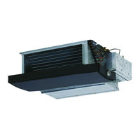
Daikin FDXS25E7VMB Service Manual (462 pages)
Super Multi NX E / F / G / K-Series
Brand:
Daikin
| Category:
Air Conditioner
| Size: 19.52 MB
Table of Contents
Table of Contents
3
Introduction
8
Safety Cautions
8
Used Icons
12
Part 1 List of Functions
13
Cooling Only
14
Outdoor Unit
14
Indoor Unit
15
Heat Pump
18
Outdoor Unit
18
Indoor Unit
19
Part 2 Specifications
26
Cooling Only
27
Outdoor Unit
27
Specifications
28
Indoor Unit
29
Ceiling Mounted Cassette Type
31
Ceiling Suspended Type
32
Heat Pump
34
Outdoor Unit
34
Indoor Unit
37
Floor Standing Type
41
Duct Connected Type
44
Part 3 Printed Circuit Board Connector Wiring Diagram
49
Outdoor Unit
50
Indoor Unit
53
Ftxg25/35/50Jv1Bw(A)
53
Ftxs20/25K2V1B, Ctxs15/35K2V1B
56
Ftxs25/35/42/50J2V1B
58
Ftxs60/71Gv1B
61
Fvxg25/35/50K2V1B
64
Fvxs25/35/50Fv1B
67
Flxs25/35/50/60Bavmb
69
Fdxs25/35E7Vmb, Fdxs50/60C7Vmb
71
Fcqg35/50/60Fveb
73
Ffq25/35/50/60B9V1B
76
Fhq35/50/60Bwv1B
78
Fdbq25B8V1
80
Fbq35/50/60C8Veb
82
Wired Remote Controller
85
Brc1D528
85
Brc1E52A7, Brc1E52B7
86
Part 4 Function and Control
87
Indoor Unit Control (RA Models)
88
Temperature Control
88
Frequency Principle
88
Operation Starting Control
90
Airflow Direction Control
91
Fan Speed Control for Indoor Unit
94
RADIANT Operation
95
Indoor Unit Fan Control
96
Program Dry Operation
97
Automatic Operation
98
Thermostat Control
99
NIGHT SET Mode
101
ECONO Operation
102
HOME LEAVE Operation
103
INTELLIGENT EYE Operation
104
2-Area INTELLIGENT EYE Operation
105
Inverter POWERFUL Operation
107
Multi-Colored Indicator Lamp / TIMER Lamp
107
Other Functions
109
Weekly Timer Operation
110
Brightness Setting of the Indoor Unit Display
110
Indoor Unit Control (SA Models)
111
Drain Pump Control
111
Thermostat Sensor in Remote Controller
113
Freeze Prevention Control
115
Hot Start Control (in Heating Operation Only)
116
Function of Thermistor
117
Control Specification
119
Mode Hierarchy
119
Frequency Control
120
Controls at Mode Changing / Start-Up
123
Discharge Pipe Temperature Control
124
Input Current Control
125
Freeze-Up Protection Control
125
Heating Peak-Cut Control
126
Outdoor Fan Control
127
Liquid Compression Protection Function
127
Defrost Control
128
Low Hz High Pressure Limit
129
Outdoor Electronic Expansion Valve Control
129
Pressure Equalizing Control
131
Malfunctions
134
Part 5 Operation Manual
136
System Configuration
137
RA Indoor Unit
138
FTXG, FTXS-K, CTXS, FVXG Series - ARC466A1, A2, A6
138
Name of Parts
139
Remote Controller
141
Model Name Plate
143
Signal Receiver
143
Indoor Unit On/Off Switch
143
Titanium Apatite Photocatalytic
148
Preparation before Operation
151
Fan Operation
153
Operating Conditions
154
Operation Manual
154
Temperature Setting
159
Adjusting the Airflow Direction and Rate
160
Ra Indoor Unit
161
Comfort Airflow Operation
166
Powerful Operation
169
Outdoor Unit Quiet Operation
171
Off Timer Operation
173
On Timer Operation
176
Note for Multi System
185
FTXS-J, FTXS-G, FVXS Series - ARC452A1, A3
190
Names of Parts
194
Names of Parts
196
Opening the Front Panel
197
To Change the Airflow Rate Setting
201
Adjusting the Airflow Direction
202
Comfort Airflow and Intelligent Eye Operation
208
Quiet Operation
216
Copy Mode
224
FLXS, FDXS Series - ARC433B67, B69
230
To Change the Air Flow Rate Setting
234
Timer Operation
241
SA Indoor Unit
245
Brc1D528
245
Part 6 Service Diagnosis
260
Troubleshooting with LED
262
Indoor Unit
262
Outdoor Unit
264
Problem Symptoms and Measures
265
Service Check Function
266
RA Indoor Unit - FTXG, FTXS, CTXS, FVXG, FVXS, FLXS, FDXS Series
266
SA Indoor Unit - FCQG, FFQ, FHQ, FDBQ, FBQ Series
275
Code Indication on Remote Controller
279
RA Indoor Unit - FTXG, FTXS, CTXS, FVXG, FVXS, FLXS
279
FDXS Series
279
SA Indoor Unit - FCQG, FFQ, FHQ, FDBQ, FBQ Series
279
RA Indoor Unit - FTXG, FTXS, CTXS, FVXG, FVXS, FLXS, FDXS Series
279
Sub Codes for SA Indoor Unit
280
Outdoor Unit
281
Troubleshooting for RA Indoor Unit - FTXG, FTXS, CTXS, FVXG, FVXS, FLXS, FDXS Series
282
Indoor Unit PCB Abnormality
282
Freeze-Up Protection Control or Heating Peak-Cut Control
284
Fan Motor or Related Abnormality
286
Radiant Panel Temperature Rise, Indoor Electronic Expansion Valve (Motor Operated Valve) Abnormality, Freeze-Up Protection Control (FVXG Series Only)
290
Thermistor or Related Abnormality (RA Indoor Unit)
292
Front Panel Open / Close Fault (FTXG Series Only)
293
Signal Transmission Error (between Indoor Unit and Outdoor Unit)
294
Unspecified Voltage (between Indoor Unit and Outdoor Unit)
295
Troubleshooting for SA Indoor Unit - FCQG, FFQ, FHQ, FDBQ, FBQ Series
296
Indoor Unit PCB Abnormality
296
Drain Water Level System Abnormality
297
Fan Motor or Related Abnormality
299
Swing Motor Lock (FHQ Series Only)
301
Drain System Abnormality
302
Thermistor or Related Abnormality (SA Indoor Unit)
303
Remote Controller Thermistor Abnormality
304
Signal Transmission Error
305
(Between Indoor Unit and Remote Controller)
305
Signal Transmission Error (between Indoor Unit and Remote Controller)
305
Signal Transmission Error
306
(Between MAIN Remote Controller and SUB Remote Controller)
306
Signal Transmission Error (between MAIN Remote Controller and SUB Remote Controller)
306
Field Setting Abnormality
307
Troubleshooting for Outdoor Unit
308
Refrigerant Shortage
308
Low-Voltage Detection or Over-Voltage Detection
310
Signal Transmission Error (on Outdoor Unit PCB)
312
Unspecified Voltage (between Indoor Unit and Outdoor Unit)
313
Anti-Icing Function in Other Rooms
313
Unspecified Voltage (between Indoor Unit and Outdoor Unit) / Anti-Icing Function in Other Rooms
313
Anti-Icing Function
314
Outdoor Unit PCB Abnormality
316
OL Activation (Compressor Overload)
317
Compressor Lock
318
DC Fan Lock
319
Input Overcurrent Detection
320
Discharge Pipe Temperature Control
321
High Pressure Control in Cooling
322
Compressor Sensor System Abnormality
323
Position Sensor Abnormality
325
CT or Related Abnormality
327
Thermistor or Related Abnormality (Outdoor Unit)
329
Electrical Box Temperature Rise
331
Radiation Fin Temperature Rise
333
Output Overcurrent Detection
335
Check
337
Thermistor Resistance Check
337
Fan Motor Connector Check
338
Hall IC Check
339
Indoor Electronic Expansion Valve Coil Check
339
Power Supply Waveform Check
340
Outdoor Electronic Expansion Valve Check
341
Four Way Valve Performance Check
342
Inverter Unit Refrigerant System Check
342
Inverter Checker" Check
343
Rotation Pulse Check on the Outdoor Unit PCB
344
Installation Condition Check
345
Discharge Pressure Check
345
Outdoor Fan System Check
346
Capacitor Voltage Check
346
Power Module Check
347
Part 7 Removal Procedure
348
Outdoor Unit: 40-75 Class
349
Removal of Outer Panels
349
Removal of Electrical Box
353
Removal of Pcbs
361
Removal of Outdoor Fan / Fan Motor
366
Removal of Sound Blankets
368
Removal of Coils / Thermistors
372
Removal of Distributor
375
Removal of Four Way Valve
376
Removal of Compressor
377
Outdoor Unit: 80/90 Class
379
Removal of Outer Panels
379
Removal of Electrical Box
394
Removal of Pcbs
400
Removal of Fan Motor
404
Removal of Coils / Thermistors
405
Removal of Sound Blankets
411
Removal of Compressor
414
Part 8 Trial Operation and Field Settings
415
Pump down Operation
416
Forced Operation
417
Wiring Error Check Function
418
Trial Operation
420
RA Indoor Unit - FTXG, FTXS, CTXS, FVXG, FVXS, FLXS, FDXS Series
420
SA Indoor Unit - FCQG, FFQ, FHQ, FDBQ, FBQ Series
422
Field Settings
424
Outdoor Unit
424
RA Indoor Unit - FTXG, FTXS, CTXS, FVXG, FVXS, FLXS
427
FDXS Series
427
Jumper and Switch Settings
430
SA Indoor Unit - FCQG, FFQ, FHQ, FDBQ, FBQ Series
431
Application of Silicon Grease to a Power Transistor and a Diode Bridge
435
Part 9 Appendix
436
Piping Diagrams
437
Outdoor Unit
437
Indoor Unit
442
Wiring Diagrams
449
Outdoor Unit
449
Indoor Unit
454
Advertisement
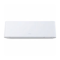
Daikin FDXS25E7VMB Service Manual (267 pages)
Inverter Multi for 2 Rooms H-Series / G-Series
Brand:
Daikin
| Category:
Heat Pump
| Size: 13.95 MB
Table of Contents
Table of Contents
3
Introduction
7
Safety Cautions
7
Used Icons
11
Part 1 List of Functions
12
Functions
13
Function and Control Part
15
Part 2 Specifications
21
Indoor Unit
22
Specifications
23
Floor Standing Type
33
Duct Connected Type
36
Ceiling Mounted Cassette Type
37
Outdoor Unit
38
Part 3 Printed Circuit Board Connector Wiring Diagram
39
Indoor Unit
40
Ftxg25/35/50Jv1Bw(S)(A)
40
Ctxs15/35K2V1B, Ftxs20/25K2V1B
42
Ftxs35/42/50K2V1B, Ftxs20/25/35/42/50J2V1B, Atxs20/25/35/42/50G2V1B
44
Ftx20/25/35Jv1B, Ftx20/25/35J2V1B, Atx20/25/35Jv1B, Atx20/25/35J2V1B
46
Fvxg25/35/50K2V1B
48
Fvxs25/35/50Fv1B
50
Flxs25/35/50Bavmb
52
Fdxs25/35Eavmb, Fdxs25/35E7Vmb, Fdxs50Cvmb, Fdxs50C7Vmb
54
Ffq25/35/50B8V1B, Ffq25/35/50B9V1B
56
Wired Remote Controller
57
Brc1D528
57
Brc1E51A7
58
Wireless Remote Controller
59
Brc7E530W
59
Outdoor Unit
60
Part 4 Function and Control
62
Function of RA Indoor Unit
63
Temperature Control
63
Frequency Principle
63
Operation Starting Control
65
Airflow Direction Control
66
Fan Speed Control for Indoor Unit
69
RADIANT Operation
71
Program Dry Operation
73
Automatic Operation
74
Thermostat Control
75
NIGHT SET Mode
76
ECONO Operation
77
HOME LEAVE Operation
78
2-Area INTELLIGENT EYE Operation
80
INTELLIGENT EYE Operation
82
Inverter POWERFUL Operation
83
Multi-Colored Indicator Lamp / TIMER Lamp
84
Brightness Setting of Indoor Unit Display
85
Clock Setting
86
WEEKLY TIMER Operation
87
Other Functions
93
Function of SA Indoor Unit
94
Drain Pump Control
94
Remote Controller
95
Thermostat Sensor in Remote Controller
96
Freeze Prevention Control
98
Hot Start Control (in Heating Operation Only)
99
Function of Thermistor
100
Control Specification
102
Mode Hierarchy
102
Frequency Control
103
Controls at Mode Changing / Start-Up
105
Discharge Pipe Temperature Control
106
Input Current Control
107
Freeze-Up Protection Control
107
Heating Peak-Cut Control
108
Outdoor Fan Control
109
Liquid Compression Protection Function
109
Defrost Control
110
Outdoor Electronic Expansion Valve Control
111
Malfunctions
115
Part 5 Remote Controller
117
RA Indoor Unit
118
Ftxg25/35/50Jv1Bw(S)(A), Ctxs15/35K2V1B, Ftxs20/25K2V1B
118
Mode Button
119
Ftxs35/42/50K2V1B
120
Ftxs20/25/35/42/50J2V1B
122
Atxs20/25/35/42/50G2V1B
124
Ftx20/25/35Jv1B, Ftx20/25/35J2V1B, Atx20/25/35Jv1B, Atx20/25/35J2V1B
126
Fvxg25/35/50K2V1B
128
Fvxs25/35/50Fv1B
130
Flxs25/35/50Bavmb
132
Fdxs25/35Eavmb, Fdxs25/35E7Vmb, Fdxs50Cvmb, Fdxs50C7Vmb
134
SA Indoor Unit
136
Brc1D528
136
Brc1E51A7
139
Operation Mode
142
Brc7E530W
144
Part 6 Service Diagnosis
145
Troubleshooting with LED
147
Indoor Unit
147
Outdoor Unit
148
Problem Symptoms and Measures
149
Service Check Function
150
RA Indoor Unit
150
Arc452 Series Remote Controller
153
Arc433 Series Remote Controller
156
SA Indoor Unit
159
Code Indication on Remote Controller
166
RA Indoor Unit
166
SA Indoor Unit
166
Outdoor Unit
167
Troubleshooting for RA Indoor Unit
168
Indoor Unit PCB Abnormality
168
Freeze-Up Protection Control or Heating Peak-Cut Control
170
Fan Motor or Related Abnormality
172
Radiant Panel Temperature Rise, Indoor Electronic Expansion Valve (Motor Operated Valve) Abnormality, Freeze-Up Protection Control (FVXG Series Only)
176
Thermistor or Related Abnormality (RA Indoor Unit)
178
Front Panel Open / Close Fault (FTXG Series Only)
179
Troubleshooting for SA Indoor Unit
180
Indoor Unit PCB Abnormality
180
Drain Level Control System Abnormality
181
Fan Motor (AC Motor) or Related Abnormality
182
Drain System Abnormality
183
Thermistor or Related Abnormality (SA Indoor Unit)
184
Remote Controller Thermistor Abnormality
185
Signal Transmission Error (between Indoor Unit and Remote Controller)
186
Signal Transmission Error (between MAIN Remote Controller and SUB Remote Controller)
187
Field Setting Abnormality
188
Troubleshooting for Outdoor Unit
189
Refrigerant Shortage
189
Low-Voltage Detection or Over-Voltage Detection
191
Outdoor Unit PCB Abnormality or Signal Transmission Error
193
Unspecified Voltage (between Indoor Unit and Outdoor Unit) / Anti-Icing Control in Other Room
196
Anti-Icing Control for Indoor Unit
197
OL Activation (Compressor Overload)
199
Compressor Lock
201
DC Fan Lock
202
Input Overcurrent Detection
203
Discharge Pipe Temperature Control
204
High Pressure Control in Cooling
205
Compressor Sensor System Abnormality
206
Position Sensor Abnormality
207
DC Voltage / Current Sensor Abnormality
209
Thermistor or Related Abnormality (Outdoor Unit)
210
Electrical Box Temperature Rise
212
Radiation Fin Temperature Rise
213
Output Overcurrent Detection
215
Check
217
Thermistor Resistance Check
217
Fan Motor Connector Output Check
218
Hall IC Check
219
Indoor Electronic Expansion Valve Coil Check
219
Power Supply Waveforms Check
220
Outdoor Electronic Expansion Valve Check
221
Four Way Valve Performance Check
222
Inverter Unit Refrigerant System Check
222
Inverter Analyzer Check
223
Rotating Pulse Input on the Outdoor Unit PCB Check
225
Installation Condition Check
226
Discharge Pressure Check
226
Outdoor Unit Fan System Check
227
Main Circuit Short Check
227
Power Module Check
228
Part 7 Trial Operation and Field Settings
229
Pump down Operation
230
Forced Cooling Operation
231
Trial Operation
232
RA Indoor Unit - FTXG, FTXS, ATXS, FTX, ATX, FVXG, FVXS, FLXS, FDXS Series
232
SA Indoor Unit - FFQ Series
234
Field Settings
236
RA Indoor Unit - FTXG, FTXS, ATXS, FTX, ATX, FVXG, FVXS, FLXS, FDXS Series
236
SA Indoor Unit - FFQ Series
242
Outdoor Unit
250
Silicon Grease on Power Transistor / Diode Bridge
251
Part 8 Appendix
252
Piping Diagrams
253
Indoor Unit
253
Outdoor Unit
257
Wiring Diagrams
258
Indoor Unit
258
Outdoor Unit
264
Removal Procedure (Booklet No.)
265
Revision History
266
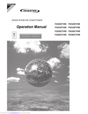
DAIKIN FDXS25E7VMB Operation Manual (28 pages)
ROOM AIR CONDITIONER
Brand:
DAIKIN
| Category:
Air Conditioner
| Size: 4.42 MB
Table of Contents
Operation Manual
1
Table of Contents
2
Safety Precautions
3
Installation Site
4
Electrical Work
4
Names of Parts
5
Outdoor Unit
6
Indoor Unit
6
Remote Controller
7
To Set the Batteries
8
Preparation before Operation
8
Operation
10
AUTO · DRY · COOL · HEAT · FAN Operation
11
To Change the Air Flow Rate Setting
12
POWERFUL Operation
13
OUTDOOR UNIT QUIET Operation
14
HOME LEAVE Operation
15
TIMER Operation
17
To Use on Timer Operation
18
To Combine on Timer and off Timer
18
Note for Multi System
19
Care and Cleaning
21
Before a Long Idle Period
22
Trouble Shooting
23
Check Again
24
Call the Service Shop Immediately
25
Disposal Requirements
25
Important Information Regarding the Refrigerant Used
25
Fault Diagnosis
26
Advertisement
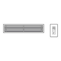
Daikin FDXS25E7VMB Installation Manual (17 pages)
Brand:
Daikin
| Category:
Air Conditioner
| Size: 1.35 MB
Table of Contents
Safety Precautions
3
Choosing a Site
4
Preparations before Installation
5
Install the Suspension Bolts
5
Indoor Unit Installation
7
Outdoor Unit Installation
8
Refrigerant Piping Work
9
Selection of Copper and Heat Insulation Materials
9
Drain Piping Work
10
Installing the Duct
11
Main Unit
11
Trial Operation and Testing
13
Advertisement
Related Products
DAIKIN Super Multi NX FDXS25EAVMB
DAIKIN FDXS25F2VEB
Daikin Inverter FDXS25CVMB
Daikin FDXS25CVMA
Daikin FDXS25CAVMB
Daikin FDXS25LVMA
Daikin FDXS25CVMB FDKS25CVMB FDXS35CVMB FDKS35CVMB CDXS50CVMB
DAIKIN Super Multi NX FDXS50CVMB
DAIKIN Super Multi NX FDXS35EAVMB
DAIKIN FDXS35E7VMB
DAIKIN Categories
Air Conditioner
Heat Pump
Remote Control
Chiller
Fan
More DAIKIN Manuals
Login
Sign In
OR
Sign in with Facebook
Sign in with Google
Upload manual
Upload from disk
Upload from URL