Sign In
Upload
Manuals
Brands
Bard Manuals
Air Conditioner
QW Series
Bard QW Series Manuals
Manuals and User Guides for Bard QW Series. We have
4
Bard QW Series manuals available for free PDF download: Literature Assembly, User Manual, Installation Instructions Manual
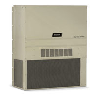
Bard QW Series Literature Assembly (128 pages)
WALL-MOUNT AIR CONDITIONER AND HEAT PUMPS
Brand:
Bard
| Category:
Heat Pump
| Size: 4.66 MB
Table of Contents
Table of Contents
14
General
15
Recovery Equipment Rated for R-410A
15
Leak Detectors
15
Gauge Manifold
15
Attaching Gauge Manifold
15
Attaching Manifold Hose to Schrader Valve
16
Leak Test
16
Evacuation
16
Charging
17
Preliminary Charging Steps
17
Charging the System by Weight
17
Figure 1: Typical AC System Cooling Cycle
18
Figure 2: Typical HP System Cooling Cycle
19
Figure 3 Heating Cycle
20
Troubleshooting the Mechanical System
21
Air Conditioning & Heat Pump - Cooling
21
Low Suction - Low Head Pressure
21
High Suction - Low Head Pressure
21
Low Suction - High Head Pressure
21
High Suction - High Head Pressure
21
Heat Pump - Heating
21
Table of Contents
26
General Information
28
Air Conditioning System
28
Wall-Mount Air Conditioner Units
28
General
28
Shipping Damage
28
Additional Publications
28
Using the TEC-EYE TM
30
TEC-EYE Hand-Held Service Tool
30
Alarm Log
31
Information
31
Status Screen
31
TEC-EYE Acronyms
31
TEC-EYE Screen Structure and Password Level
31
Additional Features
33
Addressing Wall-Mount Units
33
Model/Number Verification
33
Model/Serial Number Retain
33
Setting Unit Zone
33
Software Versioning Guide
33
Time/Date/Timezone Sync
33
Changing Free Cooling Type
34
Entering Model/Serial Number
34
Executing a Self Test
34
Parameter Description
34
Alarms
35
Acknowledging/Clearing Alarms
35
Clearing Alarm Logs
35
Clearing Alarms
35
Alarm Adjustment
35
Mixed Air Alarm
35
Economizer Damper
36
Refrigerant High Pressure
36
Refrigerant Low Pressure
36
Freezestat
37
Control Operation
38
On/Off Control
38
Blower Control
38
Balanced Climate Mode
38
Balanced Climate Enable/Disable
38
Temperature Control
39
Cooling Sequence - Economizer Available
39
Heating Sequence
40
Free Cooling
40
Economizer Disable
40
Drybulb Only
41
Economizer Enable
41
Economizer Modulation
41
Enthalpy
41
None
41
Temperature and Humidity (Default)
41
Emergency Cooling
42
Unit Disable
42
Compressor
42
Delays and Run Time
42
Enable
42
Electric Reheat Dehumidification
42
General Refrigerant Information
46
General
46
Topping off System Charge
46
Safety Practices
46
R410A Refrigerant Charge
46
Componentry
48
High Pressure Switch
48
Three Phase Scroll Compressor Start up Information
48
Phase Monitor
48
Condenser Fan Operation
48
Low Ambient Control
48
Compressor Control Module (CCM)
48
Delay-On-Make Timer
48
Brownout Protection W/Adjustment
49
High Pressure Detection
49
Short Cycle Protection/Delay-On-Break
49
Test Mode
49
Pressure Service Ports
50
Outdoor Fan Motor
50
Maintenance and Troubleshooting
53
Standard Maintenance Procedures
53
Removal of Fan Shroud
53
Troubleshooting Nidec Selectech ECM Motors
54
Dirty Filter Switch
56
Dirty Filter Switch Adjustment
56
8301-057 Airflow Differential/Dirty Filter Switch
58
8301-067 Outdoor Temperature/Humidity Sensor
58
8408-044 Return Air Sensor/Suction Sensor
61
Table of Contents
65
General Information
66
List of Necessary Materials/Tools
69
Site Preparation
70
Model Identification
70
New Shelter Installation Vs. Retrofit Installation
70
Minimum Clearance
70
Clearance to Combustibles
70
Wall-Mount Unit Mounting
72
Mounting the Units
72
Wall-Mount Unit Wiring
78
Main Power Wiring
78
Low Voltage Wiring
78
Preliminary Start up
82
Running in Orphan Mode
82
LC6000 Controller Installation
83
LC6000 Controller
84
Mounting the LC Controller
84
Installing Remote Indoor Temperature/Humidity Sensor(S)
85
Sensor
86
Generator Run Connections
88
Communication Wiring
89
Supply Wiring
94
System Set up
97
TEC-EYE Hand-Held Diagnostic Tool
97
TEC-EYE Status Screen
98
Setting up Wall-Mount Units for Operation
98
Setting up LC6000 for Operation
99
1 Address each Wall-Mount Unit
98
2 Execute a Run Test on each Unit
98
3 Clear Unit Alarm Logs on each Unit
99
4 Set LC Controller Date and Time
99
5 Configure Sensors
100
6 Enter Total Number of Units
103
7 Verify Units Are Online
103
8 Select Economizer Type for each Zone
103
9 Clear Controller Alarm Logs
104
10 Complete Installation
104
Additional Information
105
Menu Screens and Password Levels
105
Setpoints
105
Calibrating Sensors
105
Remote Indoor Temperature/Humidity Sensor Orientation
107
Advertisement
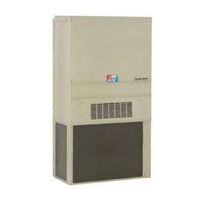
Bard QW Series Literature Assembly (137 pages)
Brand:
Bard
| Category:
Air Conditioner
| Size: 3.67 MB
Table of Contents
Table of Contents
12
General
13
Recovery Equipment Rated for R-410A
13
Leak Detectors
13
Gauge Manifold
13
Attaching Gauge Manifold
13
Attaching Manifold Hose to Schrader Valve
14
Leak Test
14
Evacuation
14
Charging
15
Preliminary Charging Steps
15
Charging the System by Weight
15
Figures
16
Figure 1: Typical AC System Cooling Cycle
16
Figure 2: Typical HP System Cooling Cycle
17
Figure 3 Heating Cycle
18
Troubleshooting the Mechanical System
19
Air Conditioning & Heat Pump - Cooling
19
Low Suction - Low Head Pressure
19
High Suction - Low Head Pressure
19
Low Suction - High Head Pressure
19
High Suction - High Head Pressure
19
Heat Pump - Heating
19
Installation Instructions
24
Getting Other Information and Publications
25
Figures
26
Figure 1
26
Installation
26
Shipping Damage
26
General
26
Installation Wood Framed Walls
26
Wood Framed Installation
26
Application of Sealant to Flanges
27
Masonry Construction Installation
28
Typical Installation
29
Installation through a Window Opening
31
Table of Contents
34
QW General Information
41
Shipping Damage
41
Unit Removal from Skid
41
Handling Unit after Removal from Skid
41
Removal of Wall Bracket from Shipping Location
42
General
42
Minimum Installation Height
42
Duct Work
45
Filters
45
Condensate Drain
45
Mist Eliminator Service
47
Installation
49
Mounting the Unit
49
Wiring - Main Power
52
Wiring - Low Voltage Wiring
52
General
52
Low Voltage Connections
53
Valve and Actuator Installation/Removal
60
Valve Installation
60
Iseries Smart Actuator Removal and Installation
60
Start up
61
Description of Standard Equipment
61
Important Installer Note
62
Phase Monitor
62
Rated CFM
62
Service Hints
62
Adjustments
63
Pressure Service Ports
64
Piping Access to Unit
64
System Start up
64
Sequence of Operation
69
Cooling
69
Heating
69
Geothermal Logic Control
69
Modulating Water Line Control
70
Iseries Smart Actuator
71
Dehumidification
72
Model Features
72
Special Features
72
Closed Loop
83
Circulation System Design
83
Copper Water Coil Application
83
Start up Procedure for Closed Loop System
84
Open Loop (Well System Applications)
86
Water Connections
86
Well Pump Sizing
87
System Start up Procedure for Open Loop Applications
87
Water Corrosion
88
Remedies of Water Problems
88
Lake and Pond Installations
89
Cooling Tower/Boiler Application
91
Service
94
Unbrazing System Components
94
Troubleshooting Geothermal Logic CCM
94
Troubleshooting Water Modulating Actuator Diagnostics
95
Troubleshooting Modulating Water Line Control Board
97
Compressor Solenoid
98
Water to Air Heat Pump
102
Quick Reference Troubleshooting Chart for
102
Ground Source Heat Pump Performance Report
102
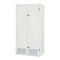
Bard QW Series User Manual (87 pages)
Brand:
Bard
| Category:
Air Conditioner
| Size: 3.2 MB
Table of Contents
Table of Contents
14
General
15
Recovery Equipment Rated for R-410A
15
Leak Detectors
15
Gauge Manifold
15
Attaching Gauge Manifold
15
Attaching Manifold Hose to Schrader Valve
16
Leak Test
16
Evacuation
16
Charging
17
Preliminary Charging Steps
17
Charging the System by Weight
17
Figure 1: Typical AC System Cooling Cycle
18
Figure 2: Typical HP System Cooling Cycle
19
Figure 3 Heating Cycle
20
Troubleshooting the Mechanical System
21
Air Conditioning & Heat Pump - Cooling
21
Low Suction - Low Head Pressure
21
High Suction - Low Head Pressure
21
Low Suction - High Head Pressure
21
High Suction - High Head Pressure
21
Heat Pump - Heating
21
Getting Other Information and Publications
27
Wall Mount General Information
28
Air Conditioner Wall Mount Model Nomenclature
28
Shipping Damage
28
General
28
Duct Work
29
Filters
29
Filter Removal/Installation
29
Switching Filter Sizes
30
Fresh Air Intake
31
Condensate Drain
31
Installation
32
Basic Installation Design and Application Planning
32
Wall Construction
32
Outdoor Area Inspection
32
Condensate Water Drainage
32
Indoor Ducted and Non-Ducted Applications
32
Indoor Supply Airflow
32
Indoor Return Airflow
32
Ducted Applications
32
Free Blow Applications
33
Thermostat or Indoor Temperature Sensor Placement
33
Unit Installation
33
Materials/Tool List
33
Wall Preparation
34
Wall Mount Installation to Wall Surface
34
Table 1 Clearance Required for Service Access and Adequate Condenser Airflow
34
Table 2 Minimum Clearances Required to Combustible Materials
35
Wiring - Main Power
41
High Voltage Connections
41
Wiring - Low Voltage
42
Low Voltage (24VAC) Connections
42
Unit Shutdown Feature
42
Balanced Climate TM Feature
42
Table 3 Additional Low Voltage Connections (if Applicable)
42
Dehumidification Feature
43
Ventilation Features
43
Alarm Relay Feature
43
DDC Controls Feature
43
Dirty Filter Switch Indicator (DFS)
43
Discharge Air Sensor
43
Airflow Switch
43
Compressor Current Sensor
43
Table 4 Low Voltage Connections for DDC Control
43
Table 5A Wall Thermostats - 2 Stage
44
Table 5B Wall Thermostats - 3 Stage
44
Table 6 Humidity Controls
44
Table 7 CO Controllers
44
Table 8 Thermostat Wire Size
44
Start up
47
General
47
Topping off System Charge
47
Safety Practices
47
Important Installer Note
47
Service Hints
47
High Pressure Switch
47
Three Phase Scroll Compressor Start up Information
48
Phase Monitor
48
Condenser Fan Operation
48
Vent Connection Plug
48
Compressor Control Module
48
Features
48
Delay-On-Make Timer
48
Short Cycle/Delay-On-Break
48
Low Pressure Detection
48
High Pressure Detection
49
Test Mode
49
Brownout Protection with Adjustment
49
Pressure Service Ports
50
Sequence of Operation
50
Cooling
50
No Economizer
50
With Economizer
50
Balanced Climate TM Mode
50
Service
52
Troubleshooting Nidec Selectech Series ECM Motors
52
If the Motor Is Running
52
If the Motor Is Not Running
52
Model Selectech Communication Diagnostics
53
Compressor Solenoid
54
Compressor Solenoid Test Procedure
54
Fan Blade Setting Dimensions
54
Table 9 Fan Blade Dimensions
54
Removal of Fan Shroud
55
R-410A Refrigerant Charge
55
Table 10A 2Nd Stage Cooling Pressures - Standard Airflow
56
Table 10B 1St Stage Cooling Pressures - Balanced Climate Airflow
56
Table 11 Electrical Specifications
57
Setting Unit Airflow
58
Blower Speeds
58
Table 12 Recommended Airflow
58
Table 13 Blower Speeds for Unit Operational Modes
58
Speed Tap 1 - Vent/Blower Only
59
Speed Tap 2 - Balanced Climate
59
Speed Tap 3 - Default lo Cooling
59
Heating
59
Speed Tap 4 - Optional MED Cooling
59
Speed Tap 5 - Optional HI Cooling
59
Dirty Filter Switch
59
Dirty Filter Switch Adjustment
59
Table 14 Indoor Blower Performance
62
Table 15 Maximum ESP Electric Heat Only
63
Table 16 Electric Heat
63
Table 17 Vent and Control Options
63
Table 18 Optional Accessories
64
Advertisement
Bard QW Series Installation Instructions Manual (50 pages)
GEOTHERMAL R-410A STAGED CAPACITY PACKAGED HEAT PUMP
Brand:
Bard
| Category:
Heat Pump
| Size: 1.45 MB
Table of Contents
Table of Contents
2
Getting Other Information and Publications for more Information, Contact These Publishers
4
QW General Information QW Model Nomenclature
5
Figure 1 Unit Dimensions
6
Shipping Damage
7
Unit Removal from Skid
7
Handling Unit after Removal from Skid
7
Figure 2 Removal of Unit from Skid
7
Removal of Wall Bracket from Shipping Location
8
General
8
Minimum Installation Height
8
Figure 3 Proper Handling of Unit after Removal from Skid
8
Figure 4 Installation of Unit W/Wall Sleeve
9
Figure 5 Installation with Free Blow Plenum
10
Figure 6 Ducted Application
10
Duct Work
11
Filters
11
Condensate Drain
11
Figure 7 Supply Duct Connections
11
Figure 8A Condensate Drain
12
Figure 8B Optional Rear Drain
12
Mist Eliminator Service
13
Figure 8C Rear Drain (Top View)
13
Figure 9 Removal of Q-TEC ERV
14
Installation
15
Mounting the Unit
15
Figure 10 Remove Locking Screws from Wheels
15
Figure 11 Unit Mounting Without Wall Sleeve
16
Figure 12 Component Location
17
Wiring - Main Power
18
Wiring - Low Voltage Wiring
18
General
18
Low Voltage Connections
19
Figure 13 Low Voltage Wire Harness Plug
19
Figure 14 Remote Thermostat Wiring "X" Option
20
Figure 15 Factory Mounted T-Stat Wiring "D" Option
21
Figure 16 Factory Mounted T-Stat Wiring "H" Opt . 22 Figure 17 Remote Thermostat Wiring "K" Option
23
Figure 18 Fact. Mounted T-Stat "1" & "3" Opt
24
Figure 19 Fact. Mounted Completestat™ Opt
25
Start up
26
Description of Standard Equipment
26
Adjustments
27
Figure 20 CO2 Control Configuration
27
Optional CFM
28
Important Installer Note
28
Phase Monitor
28
Service Hints
28
Sequence of Operation
28
Pressure Service Ports
29
Piping Access to Unit
29
Figure 21 Fluid Connections W/Ventilation Wall Sleeve
30
Figure 22 Fluid Connections W/O Ventilation Wall Sleeve
31
Pressure Tables
32
Optional Accessories
33
Closed Loop
34
Circulation System Design
34
Copper Water Coil Application
34
Figure 23 Circulation System
34
Start up Procedure for Closed Loop System
35
Figure 24 Water Temperature and Pressure Test Procedure
35
Figure 25 Performance Model WGPM-1C
36
Figure 26 Performance Model WGPM-2C
36
Open Loop (Well System Applications)
37
Water Connections
37
Figure 27 Piping Diagram
37
Well Pump Sizing
38
Start up Procedure for Open Loop System
38
Water Corrosion
39
Remedies of Water Problems
39
Lake and Pond Installations
40
Figure 28 Cleaning Water Coil
40
Figure 29 Water Well System
41
Cooling Tower/Boiler Application
42
Figure 30 Water Source H/P Cooling Cycle
43
Figure 31 Water Source H/P Heating Cycle
44
Service
45
Unbrazing System Components
45
Troubleshooting GE ECM™ Blower Motors
46
Figure 32 Control Disassembly
47
Figure 33 Winding Test
47
Figure 34 Drip Loop
47
Quick Reference Troubleshooting Chart for Water to Air Heat Pump
48
Ground Source Heat Pump
49
Performance Report
49
Advertisement
Related Products
Bard QWVS42-19
Bard QW3S3DB
Bard QW5S3DA
Bard QW4S3-B
Bard QW5S3-B
Bard QW5S3-C
Bard QW2S3DA0Z
Bard QW3S3DC0Z
Bard QW4S3DA0Z
Bard QW4S3DC0Z
Bard Categories
Air Conditioner
Heat Pump
Medical Equipment
Furnace
Controller
More Bard Manuals
Login
Sign In
OR
Sign in with Facebook
Sign in with Google
Upload manual
Upload from disk
Upload from URL