Table of Contents
Advertisement
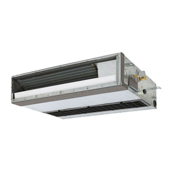
SERVICE MANUAL
MMD-AP0071SPH (-C, -K),
MMD-AP0091SPH (-C, -K),
MMD-AP0121SPH (-C, -K),
MMD-AP0151SPH (-C, -K),
MMD-AP0181SPH (-C,
• This Service Manual describes contents of the new Slim Duct indoor unit.
For the outdoor unit, refer to the Manual with FILE NO. A03-009.
MMD-AP0071SH-C,
MMD-AP0091SH-C,
MMD-AP0121SH-C,
MMD-AP0151SH-C,
MMD-AP0181SH-C,
FILE NO. A05-006
<Slim Duct Type>
-K),
PRINTED IN JAPAN, Jul.,2005 ToMo
Advertisement
Table of Contents
Troubleshooting

Related Manuals for Toshiba MMD-AP0071SH-C


Summary of Contents for Toshiba MMD-AP0071SH-C
-
Page 1: Service Manual
MMD-AP0071SPH (-C, -K), MMD-AP0091SPH (-C, -K), MMD-AP0121SPH (-C, -K), MMD-AP0151SPH (-C, -K), MMD-AP0181SPH (-C, -K), MMD-AP0071SH-C, MMD-AP0091SH-C, MMD-AP0121SH-C, MMD-AP0151SH-C, MMD-AP0181SH-C, • This Service Manual describes contents of the new Slim Duct indoor unit. For the outdoor unit, refer to the Manual with FILE NO. A03-009. -
Page 2: Table Of Contents
CONTENTS SAFETY CAUTION .................... 3 1. CONSTRUCTION VIEWS (EXTERNAL VIEWS) ........8 2. WIRING DIAGRAM ..................9 3. PARTS RATING ..................10 4. FAN CHARACTERISTICS ................ 50 5. REFRIGERANTING CYCLE DIAGRAM ........... 52 6. CONTROL OUTLINE ................53 7. APPLIED CONTROL ................57 8. -
Page 3: Safety Caution
SAFETY CAUTION The important contents concerned to the safety are described on the product itself and on this Service Manual. Please read this Service Manual after understanding the described items thoroughly in the following contents, and keep them. WARNING Before troubleshooting or repair work, check the earth wire is connected to the earth terminals of the main unit, otherwise an electric shock is caused when a leak occurs. - Page 4 WARNING After repair work, surely assemble the disassembled parts, and connect and lead the removed cables as before. Perform the work so that the cabinet or panel does not catch the inner cables. If incorrect assembly or incorrect cable connection was done, a disaster such as a leak or Assembly/Cabling fire is caused at user’s side.
- Page 5 • New Refrigerant (R410A) This air conditioner adopts a new HFC type refrigerant (R410A) which does not deplete the ozone layer. 1. Safety Caution Concerned to New Refrigerant The pressure of R410A is high 1.6 times of that of the former refrigerant (R22). Accompanied with change of refrigerant, the refrigerating oil has been also changed.
- Page 6 4. Tools (1) Required Tools for R410A Mixing of different types of oil may cause a trouble such as generation of sludge, clogging of capillary, etc. Accordingly, the tools to be used are classified into the following three types. 1) Tools exclusive for R410A (Those which cannot be used for conventional refrigerant (R22)) 2) Tools exclusive for R410A, but can be also used for conventional refrigerant (R22) 3) Tools commonly used for R410A and for conventional refrigerant (R22) The table below shows the tools exclusive for R410A and their interchangeability.
- Page 7 5. Recharge of Refrigerant When recharge of the refrigerant is required, charge the new refrigerant with the specified amount in the procedure as described below. Recover the refrigerant and check there is no refrigerant in the equipment. Leave it as it is for 1 to 2 minutes and check the indicator of the compound gauge does not return.
-
Page 8: Construction Views (External Views)
803 (inside) Refrigerant piping Air filter Fresh air inlet Drain-up port (knock-out hole) Hung-up plate MMD-AP0071SPH-C, AP0091SPH-C, AP0121SPH-C, AP0151SPH-C, AP0181SPH-C, MMD-AP0071SH-C, AP0091SH-C, AP0121SH-C, AP0151SH-C, AP0181SH-C 803 (inside) Refrigerant Natural drain port piping Fresh air inlet Drain-up port (knock-out hole) (SPH model only) -
Page 9: Wiring Diagram
Non Drain pump type ("SH" Type) Non Drain pump type Drain pump type ("SH" Type) ("SPH" Type) CN34 CN68 (RED) (BLU) (External static pressure setup) 1 2 3 Color indication CN334 CN333 CN82 CN33 CN34 RED : RED 1 2 3 4 5 6 (WHI) (WHI) (BLU) -
Page 10: Parts Rating
3. PARTS RATING 3-1. Parts Rating Model MMD- AP0071SPH AP0091SPH AP0121SPH AP0151SPH AP0181SPH Fan motor SWF-280-60-1 Pulse motor EDM-MD12TF-3 Pulse motor valve EDM-B25YGTF EDM-B40YGTF Drain pump motor ∗ ADP-1409 Float switch ∗ FS-0218-102 TA sensor Lead wire length : 1558mm Vinyl tube TC1 sensor Ø4 size lead wire length : 1200mm Vinyl tube (Blue) TC2 sensor... -
Page 11: Parts Name Of Remote Controller
3-3. Parts Name of Remote Controller Display section CODE No. In the display example, all indicators are displayed for the explanation. DATA SETTING TEST Display UNIT No. section R.C. In reality only, the selected contents are indicated. TEMP. ON / OFF •... -
Page 12: Operation Section
Operation section Push each button to select a desired operation. • The details of the operation needs to be set up once, afterward, the air conditioner can be used by pushing ON / OFF button only. TEMP. ON / OFF TIMER SET MODE TIME... -
Page 13: Correct Usage
3-4. Correct Usage When you use the air conditioner for the first time or when you change the SET DATA value, follow the proce- dure below. From the next time, the operation displayed on the remote controller will start by pushing the ON / OFF button only. - Page 14 3-5. Automatic Operation (Super Heat Recovery Type Only) When you set the air conditioner in mode or switch over from AUTO operation because of some settings change, it will automatically select either cooling, heating, or fan only operation depending on the indoor tem- perature.
-
Page 15: Timer Operation
3-6. TIMER Operation A type of timer operation can be selected from the following three types. OFF timer : The operation stops when the time of timer has reached the set time. Repeat OFF timer : Every time, the operation stops after the set time has passed. ON timer : The operation starts when the time of timer has reached the set time. - Page 16 3-7. Information Confirmation before operation Protective device (High pressure switch) • Turn on the power switch 12 hours before starting This device stops automatically an operation when the operation. excessive force is applied on the air conditioner. • Make sure whether earth wire is connected. If the protective device works, the operation stops and the operation lamp flashes.
-
Page 17: Air Conditioner Operations And Performance
3-8. Air Conditioner Operations and Performance 3 minutes protection function 3-minutes protection function prevents the air conditioner from starting for initial 3 minutes after the main power switch/circuit breaker is turned on for re-starting the air conditioner. Power failure Power failure during operation will stop the unit completely. •... -
Page 18: When The Following Symptoms Are Found
3-9. When the Following Symptoms are Found Check the points described below before asking repair servicing. Symptom Cause Outdoor unit • White misty cold air • Fan of the outdoor unit stops automatically and performs defrost or water is out. operation. -
Page 19: Accessory Parts
Accessory parts H Accessory parts CAUTION To Disconnect the Appliance from Main Power Supply. Part name Q’ty Shape Usage This appliance must be connected to the main power supply by means of a switch with a contact separation of at least 3 mm. Installation Manual This manual (Be sure to hand over to customers) -
Page 20: Installation Of New Refrigerant Air Conditioner
SELECTION OF INSTALLATION PLACE INSTALLATION OF NEW REFRIGERANT AIR CONDITIONER This air conditioner adopts the new HFC refrigerant (R410A) which does not deplete the ozone layer. WARNING • R410A refrigerant is apt to be affected by impurity such as water, oxidizing membrane, or oils because the pressure of R410A refrigerant is higher than that of the former refrigerant by approx. - Page 21 SELECTION OF INSTALLATION PLACE Installation space Arranging the to back air inlet type Reserve space required for maintenance the indoor unit and service work. <Back air inlet> 5 or more 235 or more Air outlet 100 or more or more (Unit : mm) <Under air inlet>...
-
Page 22: Installation Of Indoor Unit
INSTALLATION OF INDOOR UNIT Opening hole on ceiling and placing of hanging bolt WARNING • Considering the indoor unit and the hanged-up piping/wiring work, determine the installation position and direction. Install the air conditioner certainly to sufficiently withstand the weight. •... -
Page 23: Drain Piping Work
DRAIN PIPING WORK Pipe material/Insulator and size Connection of drain pipe Check the draining CAUTION The following materials for piping work and insulating • Connect the hard socket (local supply) to the hard After drain piping work, check that water drain is •... -
Page 24: Air Ducting
DRAIN PIPING WORK Be sure to mount an air filter to the air inlet side; otherwise decrease of capacity and etc. may be caused. Insert the edge of hose into the <Under air inlet> <Back air inlet> drain pan and bend it downward. Cover plate Main unit Air filter... -
Page 25: Refrigerant Piping
REFRIGERANT PIPING • Projection margin in flaring : • Tightening torque of flare pipe connections WARNING B (Unit : mm) Pressure of R410A is higher than that of R22 by • If refrigerant gas has leaked during the installation work, ventilate the room immediately. approx. -
Page 26: Electric Work
REFRIGERANT PIPING REQUIREMENT Heat insulating process Power supply cord and communication wires specifications Apply the heat insulation to the pipe connecting Perform heat insulating for pipes at liquid side and gas Power supply cord and communication wires are procured locally. section of the indoor unit securely up to the root side separately. - Page 27 ELECTRIC WORK Cable connection Remote controller wiring • As the remote controller wire has no polarity, there is no problem if connections to indoor unit terminal blocks A REQUIREMENT and B are reversed. • Be sure to pass the wire through the wire connection port of the indoor unit. <Wiring diagram>...
-
Page 28: Applicable Controls
APPLICABLE CONTROLS <Change on wired remote controller> NOTIFICATION Setup of external static pressure Be sure to set up a tap change based upon the Setup data External static pressure When using the equipment at the first time, it will take a lot of time that the remote controller accepts an resistance (external static pressure) of the duct to be operation after power was on. -
Page 29: Test Run
TEST RUN APPLICABLE CONTROLS Before test operation Change of lighting term of filter sign Group control WARNING According to the installation condition, the lighting term In a group control, a remote controller can control up • Before turning on the power supply, carry out the following items. To protect the compressor at of the filter sign (Notification of filter cleaning) can be to maximum 8 units. -
Page 30: Troubleshooting
TROUBLESHOOTING TEST RUN In case of wireless remote controller Confirmation and check When a trouble occurred in the air conditioner, the CODE No. Procedure Description check code and the indoor unit No. appear on the UNIT No. display part of the remote controller. Remove a small screw which fixes the nameplate of the receiver unit. - Page 31 TROUBLESHOOTING Check code Wireless remote controller Check method Sensor block display Main Outdoor 7-segment display Check code name Judging device AI-NET central On the remote controller (Main remote controller, Central control remote controller) and the interface P.C. board of remote of receiving unit controller control display...
- Page 32 — — — — equipment control interface Group control branching unit error Differs according to error contents of unit with occurrence of alarm TCC-LINK — — (L20 is displayed.) Duplicated central control addresses Terminology TCC-LINK : TOSHIBA Carriea Cominication Link.
- Page 33 MAINTENANCE For maintenance, be sure to turn off the main power switch. CAUTION Do not handle the buttons with wet hands; otherwise an electric shock may be caused. <Daily maintenance> Cleaning of air filter CODE No. is displayed on the remote controller, contact to service on maintenance professional to cleaning the air filter.
- Page 34 Accessory parts H Accessory parts CAUTION To Disconnect the Appliance from Main Power Supply. Q’ty This appliance must be connected to the main power supply by means of a switch with a contact separation of Part name Shape Usage at least 3 mm. SPH model SH model with drain pump...
- Page 35 SELECTION OF INSTALLATION PLACE INSTALLATION OF NEW REFRIGERANT AIR CONDITIONER This air conditioner adopts the new HFC refrigerant (R410A) which does not deplete the ozone layer. WARNING • R410A refrigerant is apt to be affected by impurity such as water, oxidizing membrane, or oils because the pressure of R410A refrigerant is higher than that of the former refrigerant by approx.
- Page 36 MMD-AP0071SPH-C, AP0091SPH-C, AP0121SPH-C, AP0151SPH-C, AP0181SPH-C 5 or more 235 or more Air outlet Air outlet 100 or more or more MMD-AP0071SH-C, AP0091SH-C, AP0121SH-C, AP0151SH-C, AP0181SH-C Service door (Ceiling opening) <Drain piping left side> Drain piping 5 or more 235 or more Air outlet...
- Page 37 External view Notification of filter cleaning term setup The lighting term setup of the filter sign (Notification of filter cleaning) of the remote controller can be changed according to the condition of installation. If the room is not heated due to the installation place or construction of the room, the detection temperature of heating can be raised.
- Page 38 DRAIN PIPING WORK INSTALLATION OF INDOOR UNIT Opening hole on ceiling and placing of hanging bolt CAUTION • Considering the indoor unit and the hanged-up piping/wiring work, determine the installation position and direction. • In these models of the air conditioner, two types of models, the models (-APXXXXSPH series) attached with drain-up pump and the natural draining models (-APXXXXSH series) are included.
- Page 39 DRAIN PIPING WORK 5-1-3. Connection of drain pipe 5-1-5. Check the draining CAUTION • Connect the hard socket (local supply) to the hard After drain piping work, check that water drain is Pour water slowly. socket side of the attached flexible hose which has properly performed and water does not leak from the been installed.
- Page 40 DRAIN PIPING WORK 5-2. In case of drain up pump less model 5-2-3. Connection of drain pipe (MMD-AP0071SH-C to AP0181SH-C) • Connect the hard vinyl chloride pipe (procured locally) to the mounted drain Drain pan 5-2-1. Pipe material/Insulator and size hose which was attached.
- Page 41 AIR DUCTING REFRIGERANT PIPING 6-1. Arranging the Duct connection port WARNING Referring to the following dimensions, manufacture duct at the local site. • If refrigerant gas has leaked during the installation work, ventilate the room immediately. Be sure to mount an air filter to the air inlet side at the local site; otherwise decrease of capacity and etc. may be •...
- Page 42 ELECTRIC WORK REFRIGERANT PIPING • Projection margin in flaring : • Tightening torque of flare pipe connections WARNING B (Unit : mm) Pressure of R410A is higher than that of R22 by 1. Using the specified wires, ensure to connect the wires, and fix wires securely so that the approx.
- Page 43 ELECTRIC WORK Power supply cord and communication wires specifications Cable connection Power supply cord and communication wires are procured locally. REQUIREMENT For the power supply specifications, follow to the table below. If capacity is little, it is dangerous because overheat or •...
- Page 44 APPLICABLE CONTROLS ELECTRIC WORK Remote controller wiring NOTIFICATION • As the remote controller wire has no polarity, there is no problem if connections to indoor unit terminal blocks A When using the equipment at the first time, it will take a lot of time that the remote controller accepts an and B are reversed.
- Page 45 APPLICABLE CONTROLS <Change on wired remote controller> Setup of external static pressure Change of lighting term of filter sign Group control Setup data External static pressure Be sure to set up a tap change based upon the According to the installation condition, the lighting term In a group control, a remote controller can control up resistance (external static pressure) of the duct to be of the filter sign (Notification of filter cleaning) can be...
- Page 46 TEST RUN In case of wireless remote controller Before test operation WARNING • Before turning on the power supply, carry out the following items. To protect the compressor at Procedure Description 1) Using 500V-megger, check there is 1MΩ or more between the starting time, keep power-ON terminal block of the power supply and the earth.
- Page 47 TROUBLESHOOTING Confirmation and check Check method When a trouble occurred in the air conditioner, the On the remote controller (Main remote controller, Central control remote controller) and the interface P.C. board of CODE No. check code and the indoor unit No. appear on the the outdoor unit (I/F), a check display LCD (Remote controller) or 7-segment display (on the outdoor interface P.C.
- Page 48 Terminology ¤ ¡ ¤ 04: Fan IPDU error No. of IPDU error 05: IPDU1 + Fan IPDU error TCC-LINK : TOSHIBA Carriea Cominication Link. 06: IPDU2 + Fan IPDU error 07: All IPDU error ¤ ¡ ¤ Detected indoor address...
- Page 49 MAINTENANCE TROUBLESHOOTING For maintenance, be sure to turn off the main power switch. New check code CAUTION 1. Difference between the new check code and the current system The displaying method of the check code changes in this model and after. Do not handle the buttons with wet hands;...
-
Page 50: Fan Characteristics
4. FAN CHARACTERISTICS Slim Duct (Filter attached) MMD-AP0071SPH, SH MMD-AP0121SPH, SH MMD-AP0091SPH, SH Standard air volume : 540m³/h Standard air volume : 600m³/h High (50Pa) Upper limit of external High (50Pa) Upper limit of external static pressure(50Pa) static pressure(50Pa) Lower limit of Lower limit of external static external static... - Page 51 Slim Duct MMD-AP0071SPH, SH MMD-AP0121SPH, SH MMD-AP0091SPH, SH Standard air volume : 540m³/h Standard air volume : 600m³/h High (50Pa) Upper limit of external High (50Pa) Upper limit of external static pressure(50Pa) static pressure(50Pa) Upper limit of external static pressure(35Pa) High High (35Pa)
-
Page 52: Refrigeranting Cycle Diagram
5. REFRIGERANTING CYCLE DIAGRAM Liquid side Gas side Strainer Capillary tube Air heat exchanger at indoor side Pulse Motor Valve (PMV) Strainer Sensor (TCJ) Sensor (TC2) Sensor (TC1) Sensor Fan motor (TA) Functional part name Functional outline Pulse Motor Valve (Connector CN082 (6P): Blue) 1) Controls super heat in cooling operation 2) Controls under cool in heating operation... -
Page 53: Control Outline
6. CONTROL OUTLINE 6-1. Control Specifications Item Outline of specifications Remarks Power supply (1) Distinction of outdoor unit is reset. When the power supply is reset, the outdoor units are distinguished, and control is exchanged according to the distinctive results. (2) Check code clear When the power supply is reset, the check code is also reset once. - Page 54 Item Outline of specifications Remarks Prevention of (1) In all heating operation, the upper limit of the fan tap is set by cold air one with higher temperature of TC2 sensor and TCJ sensor. discharge • When B zone has continued for 6 minutes, the operation •...
- Page 55 Item Outline of specifications Remarks Recovery control (1) The indoor unit which stops operation, thermostat is OFF, • Recovery operation is for cooling or operates in FAN mode opens PMV of the indoor unit by usually executed every 2 refrigerant and oil the specified opening degree when cooling refrigerant or oil hours.
- Page 56 Item Outline of specifications Remarks “ ” and “ ” <Operation standby> ..Display on remote controller • “ ” goes on. display (1) • “P05” is one of displays of power wire missing. (Operation and • “P05” of power cable is detected. heating stand-by) •...
-
Page 57: Applied Control
7. APPLIED CONTROL 7-1. Setup of Selecting Function in Indoor Unit (Be sure to Execute Setup by a Wired Remote Controller) <Procedure> Execute the setup operation while the unit stops. TEMP. ON / OFF TIMER SET MODE TIME SWING/FIX VENT FILTER RESET TEST SET CL... - Page 58 Table: Function selecting item code (DN) (Items necessary to perform the applied control at the local site are described.) Item Description At shipment Filter display delay 0000 : None 0001 : 150H According to type timer 0002 : 2500H 0003 : 5000H 0004 : 10000H Dirty state of filter 0000 : Standard...
- Page 59 TYPE Indoor unit capacity Item code [10] Item code [11] Setup data Type Abbreviated Model name Setup data Model 0005 Slim Duct MMD-AP XXX SPH, SH 0001 0003 0005 0007 0009 7-2. Applied Control in Indoor Unit n Remote location ON/OFF control box (TCB-IFCB-4E) [Wiring and setup] •...
- Page 60 n Ventilating fan control from remote controller [Function] • The start/stop operation can be operated from the wired remote controller when air to air heat exchanger or ventilating fan is installed in the system. • The fan can be operated even if the indoor unit is not operating. •...
- Page 61 n Leaving-ON prevention control [Function] • This function controls the indoor units individually. It is connected with cable to the control P .C. board of the indoor unit. • In a group control, it is connected with cable to the indoor unit (Control P .C. board), and the item code set to the connected indoor unit.
-
Page 62: Troubleshooting
8. TROUBLESHOOTING 8-1. Troubleshooting Summary 1. Before troubleshooting 1) Applied models Super Heat Recovery Multi type models (Indoor unit: MMX-APXXX, Outdoor unit: MMY-MAPXXXFT8) 2) Required tools / measuring devices • Screwdrivers (Philips, Minus), spanner, radio pinchers, nipper, push pin for reset switch, etc. •... -
Page 63: Check Code List
8-2. Check Method On the remote controller (Main remote controller, Central control remote controller) and the interface P .C. board of the outdoor unit, a check display LCD (Remote controller) or 7-segment display (on the outdoor interface P .C. board) to display the operation is provided. Therefore the operation status can be known. Using this self-diagno- sis function, a trouble or position with trouble of the air conditioner can be found as shown in the table below. - Page 64 Check code Wireless remote controller Sensor block display Outdoor 7-segment display Judging of receiving unit Main remote Check code name AI-NET central device controller control display Operation Timer Ready Flash display Sub code ¤ ¤ — — Indoor TCJ sensor error Indoor ¤...
- Page 65 Check code Wireless remote controller Sensor block display Outdoor 7-segment display Judging Main remote of receiving unit Check code name AI-NET central device controller control display Operation Timer Ready Flash display Auxiliary code ¤ ¤ — — Indoor fan motor error Indoor ¤...
- Page 66 New check code 1. Difference between the TCC LINK and AI-NET check code The displaying method of the check code changes in this model and after. AI-NET check code TCC Link Used characters Hexadecimal notation, 2 digits Alphabet + Decimal notation, 2 digits Characteristics of code Few classification of communication/ Many classification of communication/incorrect setup system...
- Page 67 8-3. Troubleshooting by Check Display on Remote Controller In case of wired remote controller (RBC-AMT31E) 1. Confirmation and check When a trouble occurred on the air conditioner, CODE No. the check code and the indoor unit No. are displayed on the display section of the remote UNIT No.
- Page 68 In case of central remote controller (TCB-SC642TLE) ZONE ZONE GROUP CODE 1234 TEST UNIT No. SET DATA SETTING R.C. GROUP SELECT ZONE 1. Confirmation and check When a trouble occurred on the air conditioner, the check code and the indoor unit No. are displayed on the display section of the remote controller.
- Page 69 8-4. Check Code and Check Position Displayed on the Remote Controller and Outdoor Unit (7-Segment Display of Interface) Check code Detected Outdoor 7-segment display Check code name Status Error detection condition Check item (position) Main AI-NET position remote central control controller Check code remote controller Sub-code...
- Page 70 Check code Detected Main Outdoor 7-segment display AI-NET Check code name Status Error detection condition Check item (position) position remote central control controller Check code Sub-code remote controller 01: Indoor/outdoor Automatic address start All stop • When indoor automatic address started, other •...
- Page 71 Check code Detected Check code Outdoor 7-segment display Status Error detection condition Check item (position) Main AI-NET position name remote central control controller Check code remote controller Sub-code 01: IPDU1 error IPDU All stop Communication of each IPDU • Check connection of communication connector and communication (P .C.
- Page 72 Check code Detected Outdoor 7-segment display Check code name Status Error detection condition Check item (position) Main AI-NET position remote central control controller Check code remote controller Sub-code 01: Compressor 1 side IPDU TH sensor error All stop • Resistance value of sensor is •...
- Page 73 Check code Detected Outdoor 7-segment display Check code name Status Error detection condition Check item (position) Main AI-NET position remote central control controller Check code remote controller Sub-code 01: Compressor 1 side IPDU Current detection All stop While header compressor •...
- Page 74 Check code Detected Outdoor 7-segment display Check code name Status Error detection condition Check item (position) Main AI-NET position remote central control controller Check code remote controller Sub-code — Protection for oil All stop The operating compressor <Check all the outdoor units in the corresponding line.> level drop detection detected oil shortage •...
- Page 75 Check code Detected Outdoor 7-segment display Check code name Status Error detection condition Check item (position) Main AI-NET position remote central control controller Check code remote controller Sub-code 01: TK1 oil circuit system error Oil level detective circuit system error All stop Temperature change of TK1 •...
- Page 76 Check code Detected Main Outdoor 7-segment display AI-NET Check code name Status Error detection condition Check item (position) position remote central control controller Check code Sub-code remote controller No. of indoor units with priority Duplicated indoor units with All stop Indoor units with priority were •...
- Page 77 Check code Detected Check code Outdoor 7-segment display Status Error detection condition Check item (position) Main AI-NET position name remote central control controller Check code remote controller Sub-code — — Indoor Indoor fan Corresponding • Check the lock of fan motor (AC fan). motor error unit only stops.
- Page 78 Check code Detected Check code Outdoor 7-segment display Status Error detection condition Check item (position) Main AI-NET position name remote central control controller Check code remote controller Sub-code 01: Compressor IPDU Heat sink All stop IGBT built-in temp sensor (TH) •...
- Page 79 Check code Detected Check code Error detection Outdoor 7-segment display Status Check item (position) Main AI-NET position name condition remote central control controller Check code remote controller Sub-code — Discharge All stop Discharge temperature • Check full opening of outdoor service valves (gas side, liquid side). temp TD2 error (TD2) exceeded 115°C.
- Page 80 Check code Detected Outdoor 7-segment display Check code name Status Error detection condition Check item (position) Main AI-NET position remote central control controller Check code remote controller Sub-code 0: IGBT shortage FAN-IPDU Outdoor fan IPDU All stop (Sub-code: 0) • Check fan motor. (Interphase short-circuit) error 1: Position detection •...
- Page 81 Error detected by TCC-LINK central control device Check code Error detection Outdoor 7-segment display Detected position Check code name Status Check item (position) Display on AI-NET condition central control central control device remote controller Sub-code • Check central control device error. —...
- Page 82 Cautions when servicing for compressor 1. Removing wires of both compressors check output of the inverter as described below. How to check inverter output 1. Turn off the power supply. 2. Remove the compressor lead cables from the compressors. (Be sure to remove lead cables of both compressors.) 3.
-
Page 83: Diagnosis Procedure For Each Check Code
8-5. Diagnosis Procedure for Each Check Code Check code Check code name Cause of operation [E03] / [97] Communication error between No communication from remote controller and Check code Check code name Cause of operation indoor and remote controller communication adaptor (d07 / AI-NET) (Detected at indoor side) [E01] / [–]... - Page 84 Check code Check code name Cause of operation Check code Check code name Cause of operation [E06] / [04] Decreased number of indoor units [E07] / [–] Indoor/Outdoor 1. Communication lines (U1, U2) connection 1. Indoor/outdoor communication end terminal error between indoor and outdoor communication circuit error resistance setup error (d07 / AI-NET)
- Page 85 Check code Check code name Cause of operation Check code Check code name Cause of operation [E08] / [96] Duplicated indoor addresses [E12] / [42] Automatic address start error Indoor addresses are duplicated. 1. When indoor automatic address started, other refrigerant circuit system was setting (d07 / AI-NET) (d07 / AI-NET) automatic address.
- Page 86 Check code Check code name Cause of operation Check code Check code name Cause of operation [E16] / [89] Connected indoor units [E18] / [97/99] Communication error between 1. There are 48 or more connected indoor units. Regular communication between indoor header capacity over indoor header and follower and follower is unavailable.
- Page 87 Check code Check code name Cause of operation Check code Check code name Cause of operation [E20] / [42] Unit connected to other line [E25] / [15] Duplicated address setup of When starting automatic indoor address, a Addresses are duplicated by manual setting of during automatic address device in other line is connected.
- Page 88 Check code Check code name Cause of operation Check code Check code name Cause of operation [E31] / [CF] IPDU communication error [F01] / [0F] Indoor TCJ sensor error 1. Connection error of communication line TCJ sensor Open/Short between IPDU and I/F P.C. board (d07 / AI-NET) (d07 / AI-NET) 2.
- Page 89 Check code Check code name Cause of operation Check code name Check code name Cause of operation [F04] / [19] TD1 sensor error [F10] / [0C] Indoor TA sensor error TD1 sensor Open/Short TA sensor Open/Short (d07 / AI-NET) (d07 / AI-NET) This error code means detection of Open/Short of TD1 sensor.
- Page 90 Check code name Check code name Cause of operation Check code name Check code name Cause of operation [F15] / [18] Outdoor temp sensor miscabling [F23] / [43] Ps sensor error 1. Misinstallation and misconnection of TE1 Output voltage error of Ps sensor (TE1, TL) sensor and TL sensor (d07 / AI-NET)
- Page 91 Check code name Check code name Cause of operation Check code name Check code name Cause of operation [H02] / [1d] Compressor error (Lock) [F31] / [1C] Outdoor EEPROM error 1. Outdoor unit power line error 1. Outdoor unit power error (Voltage, noise, etc.) (d07 / AI-NET) (d07 / AI-NET) 2.
- Page 92 Check code name Check code name Cause of operation Check code name Check code name Cause of operation [H04] / [44] Compressor 1 case thermo operation [H06] / [20] Low-pressure protective operation 1. Case thermo circuit error 1. Service valve close (d07 / AI-NET) 2.
- Page 93 Check code name Check code name Cause of operation In some cases, it may be difficult to check the leakage of clogging in the following condition of refrigerant stagnation in low ambient temperature condition. [H07] / [d7] Oil level down 1.
- Page 94 Check code name Check code name Cause of operation (*3) Check for solenoid valve of outdoor unit (For multiple outdoor unit system) [H08] / [d4] Oil level detective TK1 to TK4 sensor Open/Short a) Clogging check for SV3A valve temperature sensor error (d07 / AI-NET) •...
- Page 95 Check code name Check code name Cause of operation Check code name Check code name Cause of operation [H16] / [d7] Oil level detective circuit system error [H16] / [d7] TK3 temperature detective circuit error 1. Detachment of TK2 sensor, miscabling, 1.
- Page 96 Check code name Check code name Cause of operation Check code name Check code name Cause of operation [H16] / [d7] TK4 temperature detective circuit error [L04] / [96] Duplicated setup of outdoor line address 1. Detachment of TK4 sensor, miscabling, Outdoor line addresses are duplicated.
- Page 97 Check code name Check code name Cause of operation Check code name Check code name Cause of operation [L07] / [99] Group line in individual indoor unit [L10] / [88] Outdoor capacity unset The group line is connected in the On the outdoor IF P .C.
- Page 98 Check code name Check code name Cause of operation Check code name Check code name Cause of operation [L18] / [8A] Flow selector unit system error [L29] / [CF] IPDU quantity error An indoor unit which has been operated in 1.
- Page 99 Check code name Check code name Cause of operation Check code name Check code name Cause of operation [L30] / [b6] Interlock in indoor unit Outside error was input. [P03] / [1E] Discharge temp TD1 error 1. Service valve of outdoor unit closed. from outside (d07 / AI-NET) (d07 / AI-NET)
- Page 100 Check code name Check code name Cause of operation C All heating operation [P04] / [21] Actuation of 1. High-pressure SW error high-pressure SW Repair SV4 circuit. (d07 / AI-NET) 2. Service valve closed Is SV4 circuit normal? Coil error, clogging, 3.
- Page 101 Check code name Check code name Cause of operation Check code name Check code name Cause of operation [P07] / [1C] Heat sink overheat error [P12] / [11] Indoor fan motor error 1. Power voltage error 1. Cabling error of fan motor connector (d07 / AI-NET) 2.
- Page 102 Check code name Check code name Cause of operation Check code name Check code name Cause of operation [P13] / [47] Outdoor liquid back detection error [P15] / [AE] Gas leak detection 1. PMV1/PMV2 error 1. Outdoor unit service valve closed (d07 / AI-NET) 2.
- Page 103 Check code name Check code name Cause of operation Check code name Check code name Cause of operation [P15] / [AE] Gas leak detection [P17] / [bb] Discharge temp TD2 error 1. Outdoor unit service valve closed 1. Outdoor unit service valve closed (d07 / AI-NET) 2.
- Page 104 Check code name Check code name Cause of operation Check code name Check code name Cause of operation [P19] / [08] 4-way valve operation error [P20] / [22] High-pressure protective operation 1. 4-way valve error 1. Pd sensor error (d07 / AI-NET) 2.
- Page 105 Check code name Check code name Cause of operation [P22] / [1A] Outdoor fan IPDU error 1. Fan lock (d07 / AI-NET) 2. Fan IPDU P.C. board error 3. Overload cause All heating operation 4. External cause such as blast 5.
- Page 106 Check code name Check code name Cause of operation Check code name Check code name Cause of operation [P26] / [14] G-Tr short-circuit protection error [P29] / [16] Compressor position 1. Outdoor unit power error 1) Cable/connector connection error detective circuit error (d07 / AI-NET) 2.
- Page 107 Check code name Check code name Cause of operation [–] / [97] AI-NET communication line error AI-NET communication line error (d07 / AI-NET) Are AI-NET X and Y Correct communication line. communication lines normal? Are connections of CN01, CN02, and CN03 connectors on network adaptor P.C.
-
Page 108: Segment Display Function
8-6. 7-Segment Display Function n 7-segment display on the outdoor unit (Interface P.C. board) On the interface control P .C. board, 7-segment LED to check the operating status is provided on the control P .C. board. The displayed contents are changed by combining the setup numbers of the rotary switches (SW01, SW02, and SW03) on P .C. - Page 109 1. Data display of system information (Displayed on the header outdoor unit only) SW01 SW02 SW03 Display contents Refrigerant name Displays refrigerant name. Model with refrigerant R410A Model with refrigerant R407C System capacity [ 5] to [48] : 5 to 48HP [HP] No.
- Page 110 2. Data display of outdoor unit information (Displayed on each outdoor unit) SW01 SW02 SW03 Display contents Error data Displays outdoor unit number: [U1] to [U4] Displays check code (Latest code only is displayed.) There is no check code: [– – –] There is sub-code: Check code [∗...
- Page 111 3. Data display of outdoor cycle (Displayed on each outdoor unit) SW01 SW02 SW03 Display contents Pd pressure data Pd pressure (MPaG) is displayed with decimal data. (MPaG: Approx. 1/10 value of kg/cm G data) ∗. ∗ ∗ P d. ∗.
-
Page 112: Indoor Unit
5. Outdoor EEPROM write-in error code display (Displayed on the header unit only) ∗ The latest error code written in EEPROM of each outdoor unit is displayed. (It is used when confirming the error code after power supply has been reset.) Set SW01 to 03 as shown in the following table, and the push SW04 for 5 seconds or more to display an error code. -
Page 113: Configuration Of Control Circuit
Wired remote controller (Up to 2 units) Weekly timer Display Display driver Function setup Display Function setup Key switch Key switch DC5V Remote DC5V controller Power Power Secondary communication circuit circuit battery circuit Indoor unit Network adaptor (Option) Max. 8 units are connectable. *1 Network Indoor control P.C. - Page 114 Indoor unit Network adaptor (Option) Wireless remote controller kit Network Sensor P.C. board Indoor control P.C. board (MCC-1402) Remote adaptor Remote Remote controller EEPROM P.C. board controller controller communication (MCC-1401) communication Emergent communication circuit Power circuit circuit operation DC20V circuit Central control DC12V AI-NET...
- Page 115 Wired remote controller Weekly timer Display Display driver Function setup Display Function setup Key switch Key switch DC5V Remote DC5V controller Power Power Secondary communication circuit circuit battery circuit Indoor unit Network adaptor (Option) Wireless remote controller kit Network Sensor P.C. board Indoor control P.C.
- Page 116 Microcomputer operation LED Filter/Option error input EEPROM DC fan output Power supply Optional power supply PMV output Remote controller power supply LED DC fan return Drain pump output Float SW Fan output TCJ sensor EXCT Remote controller inter-unit cable HA (T10) TC1 sensor TA sensor Used for...
- Page 117 9-1-3. Optional Connector Specifications of Indoor P.C. Board Connector Function Specifications Remarks Humidifier output CN66 DC12V In heating, thermo ON, Fan ON, Humidifier output ON * Humidifier provided, Drain pump ON is set up by CN70 ‚ Output short-circuit or from remote controller. (DN=40) ...
-
Page 118: Detachments
10. DETACHMENTS Part name Procedure Remarks REQUIREMENT Be sure to put on gloves at working; otherwise an injury may be caused by parts, etc. • Before replacement of the parts, be sure to stop operation of the air conditioner and turn off switch of the breaker. - Page 119 Part name Procedure Remarks ƒ E-cover 1. Detachment ‚ 1) Perform work 1. of 2) Take off screws fixing E-cover, and then remove hooks of the hooking part by lifting up. (Ø4 × 10, 2 pcs) 2. Attachment E-cover E-cover E-cover 1) Hang on E-cover to hooks of the hooking part so that it does not fall down.
- Page 120 Part name Procedure Remarks … P.C. board 1. Detachment P.C. board assembly ‚ ƒ „ assembly 1) Perform works 1. of , 1. of , and 1. of 2) Disconnect connectors which are connected from P.C. board assembly to other parts. NOTE) Unlock the lock of the housing to discon- nect the connectors.
- Page 121 Part name Procedure Remarks ‡ Fan motor 1. Detachment ‚ ƒ † 1) Perform works 1. of , 1. of , 1. of 2) Remove lead wires which are connected to the following connectors of P .C. board assembly. NOTE) Unlock locks of the housing, and then remove the connectors.
- Page 122 Part name Procedure Remarks ‰ Drain pump, Float 1. Detachment Drain hose ‚ switch, Drain hose 1) Perform works in procedures 1. of , 1. ƒ ˆ Only for , 1. of Hose band Drain pump MMD-AP0071SPH 2) Disconnect lead wires which are to AP0181SPH connected to the following connectors of MMD-0071SPH-C...
-
Page 123: Board Exchange Procedures
11. P.C. BOARD EXCHANGE PROCEDURES 11-1. Exchange of P.C. Board for Indoor Service Part code Model type P.C. board model Label display on P.C. board MMD-AP 1SPH series 431-6V-269 MCC-1402 03DD M03 MMU-AP 1SH series Requirement at exchange of P.C. board assembly for indoor service Before exchange, in the fixed memory (hereinafter EEPROM, IC10) installed on the indoor P .C. - Page 124 Method 2 Before exchange, it is impossible to read out the setup contents due to EEPROM error. Exchange of P .C. board for service & power ON: Procedure 2 ò Writing-in of the setup data such as the model name, capacity code, indoor unit address high ceiling setup, connection setup of option, etc to EEPROM based upon customer’s information: Procedure 3 ò...
- Page 125 Procedure 2 : Exchange of P.C. board for service 1. Exchange P .C. board with a P .C. board for service. In this time, the jumper line (cut) setup or the (short-circuit) connecting connector setup on the previous P .C. board should be reflected on P.C.
- Page 126 Procedure 3 : Writing-in of setup contents to EEPROM (The EEPROM contents which are installed on the service P .C. board have been set up at shipment from the factory.) TEST 1. Push buttons simultaneously for 4 seconds or more. is displayed in the UNIT No box.) In this time, is displayed in the item code (DN).
- Page 127 <Make a note of the setup contents. (Item code list (Example))> Item Memo Setup at shipment from factory Filter sign lighting time According to type Dirty condition of filter 0000: Standard Central control address 0099: Undefined Heating inlet temp. shift 0002: +2°C (Floor standing: 0) * Automatic selection Cooling Auto mode existence...
-
Page 128: Exploded Views And Parts List
12. EXPLODED VIEWS AND PARTS LIST MMD-AP0071SPH, AP0091SPH, AP0121SPH, AP0151SPH, AP0181SPH MMD-AP0071SPH-K, AP0091SPH-K, AP0121SPH-K, AP0151SPH-K, AP0181SPH-K 206, 209 232, 234 202, 220 TEST ˚C SETTING ZONE ZONE GROUP SuMoTuWeTh Fr Sa CODE PROGRAM1 1234 TEST UNIT No. ERROR PROGRAM2 SET DATA 214, 218, 227 SETTING R.C. - Page 129 Location Location Part Description Part Description 43121715 Motor, Fan, 43196109 Bushing SWF-280-60-1, 60W 43194026 Socket (0071SPH, 0091SPH, 43146555 Motor, P .M.V., 0121SPH, 0071SPH-K, EDM-MD12TF-3 0091SPH-K, 0121SPH-K) 43146677 Valve, P .M.V., 43194080 Socket, 1/2” EDM-B25YGTF-3 (0151SPH, 0181SPH, (0071SPH, 0091SPH, 0151SPH-K, 0181SPH-K) 0121SPH, 0071SPH-K, 0091SPH-K, 0121SPH-K) 43194081...
- Page 130 MMD-AP0071SPH-C, AP0091SPH-C, AP0121SPH-C, AP0151SPH-C, AP0181SPH-C 206, 209 232, 234 202, 220 TEST SETTING ZONE ZONE GROUP SuMoTuWeTh Fr Sa CODE PROGRAM1 1234 TEST UNIT No. ERROR PROGRAM2 SET DATA 214, 218, 227 SETTING R.C. PROGRAM3 WEEKLY TIMER GROUP SELECT ZONE 223, 224, 225, 210, 211 226, 229, 230...
- Page 131 Location Location Part Description Part Description 43121715 Motor, Fan, 43196109 Bushing SWF-280-60-1, 60W 43194026 Socket (0071SPH-C, 0091SPH-C, 43146555 Motor, P .M.V., 0121SPH-C) EDM-MD12TF-3 43194080 Socket, 1/2” 43146677 Valve, P .M.V., (0151SPH-C, 0181SPH-C) EDM-B25YGTF-3 (0071SPH-C, 0091SPH-C, 43194081 Nut, Flare, 1/2, IN 0121SPH-C) (0151SPH-C, 0181SPH-C) 43120222...
- Page 132 MMD-AP0071SH-C, AP0091SH-C, AP0121SH-C, AP0151SH-C, AP0181SH-C 206, 209 202, 220 TEST SETTING ZONE ZONE SuMoTuWeTh Fr Sa GROUP CODE PROGRAM1 1234 TEST UNIT No. ERROR PROGRAM2 SET DATA 214, 218, 227 SETTING R.C. PROGRAM3 WEEKLY TIMER GROUP SELECT ZONE 223, 224, 225,...
- Page 133 Location Location Part Description Part Description 43121715 Motor, Fan, 43196109 Bushing SWF-280-60-1, 60W 43194026 Socket (0071SH-C, 0091SH-C, 43146555 Motor, P .M.V., 0121SH-C) EDM-MD12TF-3 43194080 Socket, 1/2” 43146677 Valve, P .M.V., (0151SH-C, 0181SH-C) EDM-B25YGTF-3 (0071SH-C, 0091SH-C, 43194081 Nut, Flare, 1/2, IN 0121SH-C) (0151SH-C, 0181SH-C) 43120222...
- Page 134 MMD-AP0071SPH, AP0091SPH, AP0121SPH, AP0151SPH, AP0181SPH MMD-AP0071SPH-C, AP0091SPH-C, AP0121SPH-C, AP0151SPH-C, AP0181SPH-C MMD-AP0071SPH-K, AP0091SPH-K, AP0121SPH-K, AP0151SPH-K, AP0181SPH-K MMD-AP0071SH-C, AP0091SH-C, AP0121SH-C, AP0151SH-C, AP0181SH-C Location Location Part Description Part Description 43050382 Sensor, TC (F6) 43160478 Terminal Block 43050398 Sensor, TG (F4) 43160509 Terminal, 4P...
- Page 135 TOSHIBA CARRIER CORPORATION 2 CHOME 12-32, KONAN, MINATOKU, TOKYO, 108-0075, JAPAN Copyright © 2005 TOSHIBA CARRIER CORPORATION, ALL Rights Reserved.