Table of Contents
Advertisement
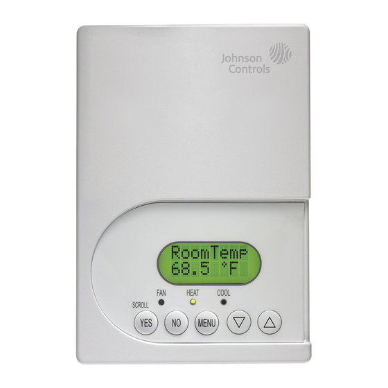
T600HPx-4 and T600HPx-4+PIR Series Heat Pump
Thermostat Controllers
Installation Instructions
T600HPN-4, T600HPP-4,
T600HPN-4+PIR, T600HPP-4+PIR
Applications
The T600HPN-4 and T600HPN-4+PIR
non-programmable and T600HPP-4 and
T600HPP-4+PIR programmable thermostat controllers
are specifically designed for control of heat pump
commercial heating and cooling equipment.
IMPORTANT: The T600HPx-4 and
T600HPx-4+PIR Series Thermostat Controllers are
intended to provide an input to equipment under
normal operating conditions. Where failure or
malfunction of the thermostat controller could lead to
personal injury or property damage to the controlled
equipment or other property, additional precautions
must be designed into the control system.
Incorporate and maintain other devices, such as
supervisory or alarm systems or safety or limit
controls, intended to warn of or protect against
failure or malfunction of the thermostat controller.
North American Emissions Compliance
United States
This equipment has been tested and found to
comply with the limits for a Class A digital device
pursuant to Part 15 of the FCC Rules. These limits
are designed to provide reasonable protection
against harmful interference when this equipment is
operated in a commercial environment. This
equipment generates, uses, and can radiate radio
frequency energy and, if not installed and used in
accordance with the instruction manual, may cause
harmful interference to radio communications.
Operation of this equipment in a residential area is
likely to cause harmful interference, in which case
the user will be required to correct the interference
at his/her own expense.
T600HPx-4 and T600HPx-4+PIR Series Heat Pump Thermostat Controllers
Part No. 24-9890-927, Rev. —
Canada
This Class (A) digital apparatus meets all the
requirements of the Canadian Interference-Causing
Equipment Regulations.
Cet appareil numérique de la Classe (A) respecte
toutes les exigences du Règlement sur le matériel
brouilleur du Canada.
Installation
Location Considerations
Locate the T600HPx-4 or T600HPx-4+PIR Series
Thermostat Controller:
•
on a partitioning wall, approximately 5 ft (1.5 m)
above the floor in a location of average
temperature
•
away from direct sunlight, radiant heat, outside
walls, outside doors, air discharge grills, or
stairwells; or from behind doors
•
away from steam or water pipes, warm air stacks,
unconditioned areas (not heated or cooled), or
sources of electrical interference
For integrated Passive Infrared (PIR) models, be sure
that the thermostat controller is located centrally, where
occupant movement is abundant.
Note: Allow for vertical air circulation to the thermostat
controller.
To install the thermostat controller:
1. Use a Phillips-head screwdriver to remove the
security screw if it is installed on the bottom of the
thermostat controller cover.
Note: Normally, the security screw comes packaged
separately in a plastic bag with the thermostat
controller. Skip this step if the screw is not installed on
the bottom of the cover.
2. Pull the bottom edge of the thermostat controller
cover and open the thermostat controller as
illustrated in Figure 1.
Issued September 17, 2009
Installation Instructions
1
Advertisement
Table of Contents

Related Manuals for Johnson Controls T600HPN-4


Summary of Contents for Johnson Controls T600HPN-4
-
Page 1: Installation Instructions
Installation Instructions Issued September 17, 2009 T600HPN-4, T600HPP-4, T600HPN-4+PIR, T600HPP-4+PIR Applications Canada The T600HPN-4 and T600HPN-4+PIR This Class (A) digital apparatus meets all the non-programmable and T600HPP-4 and requirements of the Canadian Interference-Causing T600HPP-4+PIR programmable thermostat controllers Equipment Regulations. are specifically designed for control of heat pump commercial heating and cooling equipment. - Page 2 Note: PIR models have a wiring connection between 6. Drill a 3/16 in. (5 mm) hole at each of the two the cover and the Printed Circuit Board (PCB). This marked locations and tap nylon anchors (included connection allows for proper wiring of the occupancy with the thermostat controller) flush to the wall sensor.
- Page 3 Wiring 3. Reinsert the screw terminal blocks onto the PCB. When an existing thermostat controller is replaced, Note: If multiple wires are inserted into the terminals, remove and label the wires to identify the terminal be sure to properly twist the wires together prior to functions.
- Page 4 Independent Contact - Lighting - On/Off Actuation - Exhaust Fan Scom Comp 1 Valve Heat Comp 2 Remote Outside Room Temperature Temperature Sensor Sensor Note: If the same power source is used 24 VAC for the thermostat controller and the heating Thermostat Controller loads, install a jumper across RC and RH.
-
Page 5: Setup And Adjustments
Setup and Adjustments Thermostat Controller Operation Overview PIR motion detector saves energy using standby setpoints. Room Temp Backlit, plain text 70.0ºF Liquid Crystal Display (LCD) Light-Emitting Diodes (LEDs) is easy to read in any condition. indicate system activity. Five keys on the thermostat controller make operation easy and intuitive. -
Page 6: Programming Overview
Programming Overview Occupancy Sensor Operation – T600HPx-4+PIR Series Thermostat Controllers Three menus are used to view, program, and configure the T600HPx-4 and T600HPx-4+PIR Series A T600HPx-4+PIR Series Thermostat Controller (or a Thermostat Controllers: the Status Display Menu, the T600HPx-4 Series Thermostat Controller equipped Main User Menu, and the Installer Configuration Menu. -
Page 7: Configuring Inputs Di1 And Di2
Configuring the T600HPx-4 or T600HPx-4+PIR 3. When the desired parameter is displayed, use the YES key to choose the desired selection option. Series Thermostat Controller The T600HPx-4 and T600HPx-4+PIR Series 4. Press the YES key and then the NO key to Thermostat Controllers come from the factory with continue scrolling through the parameters. - Page 8 Table 2: Installer Configuration Menu (Part 2 of 7) Parameter Description and Default Selection Options Appearing on Display Configuration of Digital Input 2. (None): No function is associated with an input. Default: None (Service): A Service alarm is displayed on the thermostat controller when the input is energized.
- Page 9 Table 2: Installer Configuration Menu (Part 3 of 7) Parameter Description and Default Selection Options Appearing on Display Frost pr Provides a minimum heating (on): Enabled setpoint of 42.0°F/5.5°C to prevent (off): Disabled freezing in the zone controlled by the thermostat controller. Default: off Sets the Occupied and Unoccupied Range: 40.0°F/4.5°C to 90.0°F/32.0°C...
- Page 10 Table 2: Installer Configuration Menu (Part 4 of 7) Parameter Description and Default Selection Options Appearing on Display Fan cont Determines how the fan is activated (off): The thermostat controller does not activate the fan in in response to a call for heating. response to a call for heating.
- Page 11 Table 2: Installer Configuration Menu (Part 5 of 7) Parameter Description and Default Selection Options Appearing on Display Disables heating stage(s) operation Range: -15°F/-26°C to 120°F/49°C adjustable in 5F°/5C° increments H lock when the outside air temperature is greater than the configured value. If the fan mode is set to Auto or Smart, the fan output is also disabled.
- Page 12 Table 2: Installer Configuration Menu (Part 6 of 7) Parameter Description and Default Selection Options Appearing on Display Sets the high balance point (the Range: 34.0°F/1.0°C to 90.0°F/32.0°C Hi b. p. outside air temperature at which the auxiliary heat is not used). Default: 90.0°F/32.0°C Note: Above the high balance point, only the heat pump is used to...
-
Page 13: Operation
Table 2: Installer Configuration Menu (Part 7 of 7) Parameter Description and Default Selection Options Appearing on Display Comp/aux Sets the mode of interaction (on): In the heating mode only. If the heat pump is not able to satisfy between the heat pump and the the heating setpoint, the auxiliary heat is energized and the heat auxiliary heat. -
Page 14: Enabling Temporary Override Schedule
Note: The Override Schedule function is available on in 0.5F°/0.5C° increments; press and hold down the the T600HPN-4 and T600HPN-4+PIR models only keys to change the temperature in 5.0F°/5.0C° when DI1 or DI2 is configured as remote NSB. -
Page 15: Entering Temporary Temperature Setpoints
Table 4: Entering Permanent Temperature Table 4: Entering Permanent Temperature Setpoints (Part 2 of 3) Setpoints (Part 3 of 3) Thermostat Description Thermostat Description Controller Controller Display Display Press the NO key for all prompts until Press the YES key to set the display the temperature setpoint prompt units to °F or °C. -
Page 16: Selecting The System Mode
75.0°F only on a call for heating or cooling, for both Occupied and Unoccupied states. This is the default setting for the T600HPN-4 and Press the NO key for all prompts until T600HPN-4+PIR models. the schedule set prompt appears on Schedule the display. -
Page 17: Programming The Daily Schedule - Four-Event
Table 5: Programming the Daily Schedule – To set the time schedule for a four-event schedule, Two-Event (Part 2 of 2) follow the steps in Table 6. See Table 7 for an example of a four-event office schedule. Thermostat Description Controller Table 6: Programming the Daily Schedule –... - Page 18 Table 6: Programming the Daily Schedule – Four-Event (Part 2 of 2) Thermostat Description Controller Display Press the YES key to copy the schedule from the previous day. Copy Y/N Press the NO key to set a different previous schedule. If the YES key was pressed, the next prompt is for Wednesday.
-
Page 19: Setting Schedule Hold
Note: Review the technical specifications of the accessories prior to their use in an application. Note: The Override Schedule function is available on the T600HPN-4 and T600HPN-4+PIR models only if Repair Information DI1 or DI2 is configured for remote NSB. -
Page 20: Technical Specifications
Cover with Occupancy Sensor TEC-3-PIR Additional TE-636xx-x Series 10k ohm Johnson Controls Type II Thermistor Sensors are available; refer to the TE-6300 Series Temperature Sensors Product Bulletin (LIT-216320) for more details. The TEC-3-PIR Accessory Cover can be used to replace the existing cover on a non-PIR T600HPx-4 Series Thermostat Controller to provide occupancy sensing capability. - Page 21 The performance specifications are nominal and conform to acceptable industry standards. For application at conditions beyond these specifications, consult the local Johnson Controls office. Johnson Controls, Inc. shall not be liable for damages resulting from misapplication or misuse of its products.