Table of Contents
Advertisement
Advertisement
Chapters
Table of Contents

Related Manuals for JRC JMA-9832-SA


Summary of Contents for JRC JMA-9832-SA
- Page 1 MARINE RADAR EQUIPMENT INSTRUCTION MANUAL...
- Page 3 PREFACE Thank you very much for purchasing the JRC marine radar equipment, JMA-9800 ARPA series. This equipment is a marine radar equipment designed to obtain safe operation of marine ships. This equipment consists of a radar signal transmitter-receiver unit, a CRT display unit and a scanner unit as its main units.
- Page 4 Before Operation Pictorial Indication Various pictorial indications are included in this manual and are shown on these equipment so that you can operate them safely and correctly and prevent any danger to you and/or to other persons and any damage to your property during operation. Such indications and their meanings are as follows. Please understand them before you read this manual: This indication is shown where any person is supposed to be in danger WARNING...
-
Page 5: Cautions To Be Used During Operation
Cautions to be Used during Operation WARNING Do not touch the insides of the scanner, transmitter- receiver and display unit. Touching any high voltage area, you will get an electric shock. For maintenance, inspection and adjustment of internal parts of these equipment, consult with our sales office or distributor in your district. - Page 6 CAUTION Use these radar only as assisting devices for navigation. Also, the officer should make the final decision for maneuvering by himself. Use ARPA only as assisting device for navigation. Also, the officer should make the final decision for maneuvering by himself.
-
Page 7: Precautions Before Operation
PRECAUTIONS BEFORE OPERATION Cautions for high voltage High voltages from hundreds volts to tens of thousands volts are to be applied to the electronic equipment such radio and radar devices. You do not face any danger during normal operation, but sufficient cares are required for maintenance, inspection and adjustment of their internal components. -
Page 8: First-Aid Treatments
FIRST-AID TREATMENTS First-aid treatments As far as the victim of electric shock is not in dangerous condition, do not move him and practice artificial respiration on him immediately. Once started, it should be continued rhythmically. (1) Do not touch the victim confusedly as a result of the accident, but the rescuer may also get an electric shock. -
Page 9: When Pulse Is Beating But Breathing Has Stopped
When pulse is beating but breathing has stopped (Mouth-to-mouth respiration) Fig.1 (1) Tilt the victim’s head back as far as this face looks back. (A pillow may be inserted his neck.) (2) Push his jaw upward to open his throat wide (to spread his airway). (3) Pinch the victim’s nostrils and take a deep breath, block his mouth completely with yours and blow into his mouth strongly. -
Page 10: When Both Pulse And Breathing Have Stopped
When both pulse and breathing have stopped Perform the (Cardiac massage) Fig.2 and (Mouth-to-mouth respiration) Fig.1 When no pulse has come not to be felt, his pupils are open and no heartbeat is heard, cardiac arrest is supposed to have occurred and artificial respiration must be performed. (1) Place your both hands, one hand on the other, on the lower one third area of his breastbone and compress his breast with your elbows applying your weight on his breast so that it is dented about 2 cm (Repeat compressing his breast 50 times or so a minute). -
Page 11: Equipment Appearance
EQUIPMENT APPEARANCE Scanner Unit Type NKE-1079 (12 feet) Transmitter-receiver Unit Type NTG-3037 – ix –... - Page 12 Scanner Unit Type NKE-1075 (12 feet) – x –...
- Page 13 Scanner Unit Type NKE-1059-7 (7 feet) Scanner Unit Type NKE-1059-9 (9 feet) Transmitter-receiver Unit Type NTG-3027 – xi –...
- Page 14 Scanner Unit Type NKE-1052-6 (6 feet) Scanner Unit Type NKE-1052-9 (9 feet) – xii –...
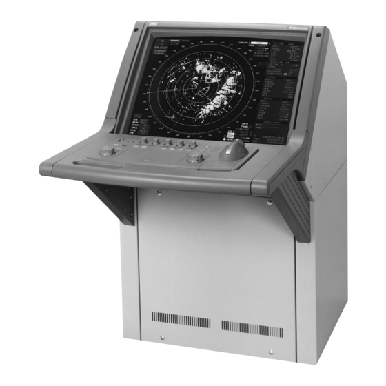
- Page 15 Display Unit Type NCD-4111 (Self-standing Type) – xiii –...
- Page 16 Monitor Unit Type NWU-228 (Desktop Type) (Option) Control Unit Type NDC-1097 (Desktop Type) (Option) Keyboard Unit Type NCE-7292 (Desktop Type) (Option) Display Unit Type NCD-4111-T (Desktop Type) (Option) – xiv –...
-
Page 17: Table Of Contents
CONTENTS PREFACE ..................i Before Operation................ii Cautions to be Used during Operation ........iii PRECAUTIONS BEFORE OPERATION Cautions for high voltage ....................v What to do in case of electric shock................v FIRST-AID TREATMENTS First-aid treatments......................vi When pulse is beating but breathing has stopped ............vii When both pulse and breathing have stopped..............viii EQUIPMENT APPEARANCE ............ix GLOSSARY ................xxii... - Page 18 3. BASIC OPERATION 3.1 FLOW OF OPERATION Power ON and Start the System...................3-2 Observe and Adjust Video ...................3-4 Tuning Operations......................3-6 Acquire and Measurement Data...................3-7 End the Operation and Stop the System...............3-7 3.2 MENU COMPOSITION ..............3-8 3.3 PREPARATION Tuning ........................3-11 Sensitivity Control .....................3-11 Display Brilliance Control ..................3-11 Contrast Control ......................3-12 Sea Clutter Suppresion....................3-12...
-
Page 19: Measurement Of Range And Bearing
Operation of Performance Monitor................3-97 EBL Maneuvering....................3-103 4. MEASUREMENT OF RANGE AND BEARING Measurement by Trackball...................4-1 Measurement by Range Rings ..................4-2 Measurement by EBLs and VRMs ................4-2 Measurement between Two Optional Points ...............4-4 5. OPERATION OF ARPA 5.1 INITIAL SETTING Setting Collision Decision Criteria ................5-2 Automatic Setting Mode (System Start) ..............5-4 Setting Range Scale......................5-4 Setting Own Ship’s Speed....................5-5... - Page 20 5.9 DELETING UNWANTED TARGETS Deleting Targets ......................5-30 5.10 ARPA SETTING Simulation ........................5-33 Gate Size ........................5-35 Test Video ........................5-37 6. TRUE AND FALSE ECHOES ON DISPLAY Radar Wave with the Holizon ..................6-1 Strength of Reflection from the Targets...............6-3 Sea Clutters ........................6-3 False Echoes.........................6-3 Display of Radar Transponder (SART) ...............6-6 7.
- Page 21 10.1 DISPOSAL OF THE UNIT ............10-1 10.2 DISPOSAL OF USED BATTERIES ...........10-1 10.3 DISPOSAL OF USED MAGNETRON........10-1 11. SPECIFICATION 11.1 JMA-9833-SA TYPE RADAR.............11-1 11.2 JMA-9832-SA TYPE RADAR.............11-2 11.3 JMA-9823-7XA/9XA TYPE RADAR ...........11-3 11.4 JMA-9822-6XA/9XA TYPE RADAR ...........11-4 11.5 SCANNER (NKE-1079) .............11-5 11.6 SCANNER (NKE-1075) .............11-6 11.7 SCANNER (NKE-1059-7/9) ............11-7...
- Page 22 Fig.106 Terminal Board Connection Diagram of Radar, Type JMA-9822-6XA/9XA Fig.107 Primary Power Supply Block Diagram of Radar, Type JMA-9833-SA Fig.108 Primary Power Supply Block Diagram of Radar, Type JMA-9832-SA Fig.109 Primary Power Supply Block Diagram of Radar, Type JMA-9823-7XA/9XA Fig.110 Primary Power Supply Block Diagram of Radar, Type JMA-9822-6XA/9XA Fig.111 Internal Connection Diagram of Scanner Unit, Type NKE-1079...
- Page 23 Fig.123 Internal Connection Diagram of CRT Monitor of Display Unit, Type NCD-4111 Fig.124 Internal Connection Diagram of Power Supply of Display Unit, Type NCD-4111 Fig.125 List of NSK and LOG Select Switches of Display Unit, Type NCD-4111 Fig.126 Setting Table of Speed LOG Select Switches of Display Unit, Type NCD-4111 Fig.127 Setting Table of Gyro Compass and Gyro Select Switches of Display Unit, Type NCD-4111...
-
Page 24: Glossary
GLOSSARY This section describes the main terms used for this equipment and general related maritime terms. ARPA: HL (Heading Line): Automatic Radar Plotting Aid Ship’s heading line AZI MODE (Azimuth Stabilization MODE): HUP (Head-Up): Bearing display mode Own ship’s heading line is always pointed to the top Anti-clutter rain (FTC): center of the radar display. - Page 25 SEA: TRAILS: Sea clutter suppression Function of displaying tracks of other ships. SET: TRIAL: The current direction for manual correction or the Trial maneuvering True Vector: current speed on the horizontal axis of the 2-axis log is displayed. A target’s true movement predicted as the result of SOG (Speed Over Ground): entering own ship’s direction and speed.
-
Page 27: General And Equipment Composition
GENERAL AND EQUIPMENT COMPOSITION NAME AND FUNCTION OF CONTROL PANEL SWITCHES AND FUNCTION OF SOFTWARE BUTTONS BASIC OPERATION MEASUREMENT OF RANGE AND BEARING OPERATION OF ARPA TRUE AND FALSE ECHOES ON DISPLAY MAINTENANCE COUNTERMEASURES FOR TROUBLE AND ADJUSTMENT AFTER-SALES SERVICE DISPOSAL SPECIFICATION APPENDIX... - Page 29 SECTION 1 GENERAL AND EQUIPMENT COMPOSITION 1.1 FUNCTIONS ............ 1-1 1.2 FEATURES ............1-3 1.3 CONFIGURATION ........... 1-5 1.4 EXTERIOR DRAWING ........1-7 1.5 GENERAL SYSTEM DIAGRAM ....1-20 1.6 COLLISION AVOIDANCE Problems of Collision Avoidance in Navigation ..1-27 Marine Accidents and Collisions .......
-
Page 30: Functions
FUNCTIONS This equipment is a high-performance radar equipment consisting of a scanner unit, a transmitter- receiver unit and a 29-inch color raster-scan CRT display unit. This radar complies with the current performance standards of the IMO. 1.1.1 Functions of This System The JMA-9800 ARPA series is a color radar system designed to comply with the international standards of the IMO. - Page 31 1.1 FUNCTIONS [$ $ ] Fourth Stage: Indication The above information must be informed to the officer maneuvering the own ship. A variety of indicating methods are available including CRT display and numerical indicator, and various data are available. This system indicates unprocessed video, vectors (to be selected from true vector and relative vector) of other ships and identification marks of danger ship or safe ship for these ships on the usual radar scope.
-
Page 32: Features
FEATURES Target Detection by Latest Signal Processing Technology The system employs the latest adaptive clutter suppression technology to eliminate undesired clutter from the radar video signals that are obtained from the receiver with a wide dynamic range, thus improving the target detection. Key Arrangement for Higher Operability The basic and main functions of the radar can be operated with the minimum necessary keys, ensuring quick action even in case of emergency. - Page 33 1.2 FEATURES Compact Design and Low Power Consumption The radiator structure making the most of wind power contributes to the substantial reduction in size and power consumption of the S band scanner unit. Self-diagnostic Program Incorporated The Self-diagnostic program always monitors all the functions of the system. If any function deteriorates, an alarm message will appear on the radar display and an alarm sounds at the same time.
-
Page 34: Configuration
Scanners and Transmitted Output Powers Radar Model Scanner Type Transmitted Output Power Band JMA-9833-SA 12 ft slot antenna 30 kW JMA-9832-SA 12 ft slot antenna 30 kW JMA-9823-7XA 7 ft slot antenna 25 kW JMA-9823-9XA 9 ft slot antenna 25 kW... - Page 35 1.3 CONFIGURATION Notes: 1. The drive motor for the scanner unit is available in 220 V AC (three-phase) type and 100/110/220 V AC (single-phase) type. 2. The scanner unit can be equipped with a deicing heater as an option marked with (*), in stead of which “-D”...
-
Page 36: Exterior Drawing
EXTERIOR DRAWING Fig.1.1 EXTERIOR DRAWING OF SCANNER UNIT, TYPE NKE-1079 Fig.1.2 EXTERIOR DRAWING OF SCANNER UNIT, TYPE NKE-1075 Fig.1.3 EXTERIOR DRAWING OF SCANNER UNIT, TYPE NKE-1059-7 Fig.1.4 EXTERIOR DRAWING OF SCANNER UNIT, TYPE NKE-1059-9 Fig.1.5 EXTERIOR DRAWING OF SCANNER UNIT, TYPE NKE-1052-6 Fig.1.6 EXTERIOR DRAWING OF SCANNER UNIT, TYPE NKE-1052-9 Fig.1.7 EXTERIOR DRAWING OF TRANSMITTER-RECEIVER UNIT, TYPE NTG-3037 Fig.1.8 EXTERIOR DRAWING OF TRANSMITTER-RECEIVER UNIT, TYPE NTG-3027... - Page 37 1.4 EXTERIOR DRAWING Fig.1.1 EXTERIOR DRAWING OF SCANNER UNIT, TYPE NKE-1079 1 – 8...
- Page 38 Fig.1.2 EXTERIOR DRAWING OF SCANNER UNIT, TYPE NKE-1075 1 – 9...
- Page 39 1.4 EXTERIOR DRAWING Fig.1.3 EXTERIOR DRAWING OF SCANNER UNIT, TYPE NKE-1059-7 1 – 10...
- Page 40 Fig.1.4 EXTERIOR DRAWING OF SCANNER UNIT, TYPE NKE-1059-9 1 – 11...
- Page 41 1.4 EXTERIOR DRAWING Fig.1.5 EXTERIOR DRAWING OF SCANNER UNIT, TYPE NKE-1052-6 1 – 12...
- Page 42 Fig.1.6 EXTERIOR DRAWING OF SCANNER UNIT, TYPE NKE-1052-9 1 – 13...
- Page 43 1.4 EXTERIOR DRAWING Fig.1.7 EXTERIOR DRAWING OF TRANSMITTER-RECEIVER UNIT, TYPE NTG-3037 1 – 14...
- Page 44 Fig.1.8 EXTERIOR DRAWING OF TRANSMITTER-RECEIVER UNIT, TYPE NTG-3027 1 – 15...
- Page 45 1.4 EXTERIOR DRAWING Fig.1.9 EXTERIOR DRAWING OF DISPLAY UNIT, TYPE NCD-4111 (SELF-STANDING TYPE) 1 – 16...
- Page 46 Fig.1.10 EXTERIOR DRAWING OF MONITOR UNIT, TYPE NWU-228 (DESKTOP TYPE) (OPTION) 1 – 17...
- Page 47 1.4 EXTERIOR DRAWING Fig.1.11 EXTERIOR DRAWING OF CONTROL UNIT, TYPE NDC-1097 (DESKTOP TYPE) (OPTION) 1 – 18...
- Page 48 Fig.1.12 EXTERIOR DRAWING OF KEYBOARD UNIT, TYPE NCE-7292 (DESKTOP TYPE) (OPTION) 1 – 19...
-
Page 49: General System Diagram
GENERAL SYSTEM DIAGRAM Fig.1.13 GENERAL SYSTEM DIAGRAM OF RADAR, TYPE JMA-9833-SA Fig.1.14 GENERAL SYSTEM DIAGRAM OF RADAR, TYPE JMA-9832-SA Fig.1.15 GENERAL SYSTEM DIAGRAM OF RADAR, TYPE JMA-9823-7XA Fig.1.16 GENERAL SYSTEM DIAGRAM OF RADAR, TYPE JMA-9823-9XA Fig.1.17 GENERAL SYSTEM DIAGRAM OF RADAR, TYPE JMA-9822-6XA Fig.1.18 GENERAL SYSTEM DIAGRAM OF RADAR, TYPE JMA-9822-9XA... - Page 50 Note: Eliminating the interference on frequencies used for marine communications and navigation due to operation of the radar. All cables of the radar are to be run away from the cables of radio equipment. (Ex. Radiotelephone. Communications receiver and dirrection finder. etc.) Especially inter-wiring cables between scanner unit and display unit of the radar should not be run parallel with the cables of radio equipment.
- Page 51 (Ex. Radiotelephone. Communications receiver and dirrection finder. etc.) Especially inter-wiring cables between scanner unit and display unit of the radar should not be run parallel with the cables of radio equipment. Fig.1.14 GENERAL SYSTEM DIAGRAM OF RADAR, TYPE JMA-9832-SA 1 – 22...
- Page 52 Note: Eliminating the interference on frequencies used for marine communications and navigation due to operation of the radar. All cables of the radar are to be run away from the cables of radio equipment. (Ex. Radiotelephone. Communications receiver and dirrection finder. etc.) Especially inter-wiring cables between scanner unit and display unit of the radar should not be run parallel with the cables of radio equipment.
- Page 53 1.5 GENERAL SYSTEM DIAGRAM Note: Eliminating the interference on frequencies used for marine communications and navigation due to operation of the radar. All cables of the radar are to be run away from the cables of radio equipment. (Ex. Radiotelephone. Communications receiver and dirrection finder. etc.) Especially inter-wiring cables between scanner unit and display unit of the radar should not be run parallel with the cables of radio equipment.
- Page 54 Note: Eliminating the interference on frequencies used for marine communications and navigation due to operation of the radar. All cables of the radar are to be run away from the cables of radio equipment. (Ex. Radiotelephone. Communications receiver and dirrection finder. etc.) Especially inter-wiring cables between scanner unit and display unit of the radar should not be run parallel with the cables of radio equipment.
- Page 55 1.5 GENERAL SYSTEM DIAGRAM Note: Eliminating the interference on frequencies used for marine communications and navigation due to operation of the radar. All cables of the radar are to be run away from the cables of radio equipment. (Ex. Radiotelephone. Communications receiver and dirrection finder. etc.) Especially inter-wiring cables between scanner unit and display unit of the radar should not be run parallel with the cables of radio equipment.
-
Page 56: Collision Avoidance
COLLISION AVOIDANCE ……Problems of Collision Avoidance in Navigation ………………… Marine collision avoidance is one of the problems that have been recognized from of old. Now, it will be described briefly who the collision avoidance is positioned among the navigational aid problems. The navigation pattern of all mobile craft constitues a system with some closed loops regardless of the media through which the mobile craft travels, whether air, water, the boundary between air and water, or space. -
Page 57: Basic Concept Of Collision Avoidance
1.6 COLLISION AVOIDANCE ……Basic Concept of Collision Avoidance …………………………… There are two aspects in collision avoidance: collision prediction and avoidance. Collision prediction is to predict that two or more vessels will happen to occupy the same point at the same time, while collision avoidance is to maneuver vessels not to occupy the same point at the same time. -
Page 58: Relative Vector And True Vector
……Relative Vector and True Vector …………………………………… From two points of view, collision prediction and avoidance, it is necessary to obtain the relative vector of other ship for prediction and the true vector of other ship for collision avoidance in order to grasp other ship’s aspect. -
Page 59: Name And Function Of
SECTION 2 NAME AND FUNCTION OF CONTROL PANEL SWITCHES AND FUNCTION OF SOFTWARE BUTTONS 2.1 NAME AND FUNCTION OF CONTROL PANEL SWITCHES ..2-1 2.2 FUNCTION OF SOFTWARE BUTTONS ....2-6... -
Page 60: Name And Function Of Control Panel Switches
NAME AND FUNCTION OF CONTROL PANEL SWITCHES Example of Display 2 – 1... - Page 61 2.1 NAME AND FUNCTION OF CONTROL PANEL SWITCHES Name and Function of Control Panel Switches 2 – 2...
- Page 62 q [PWR] (Power Supply) Switch When this switch is set to ON, the lamp lights to start the system. w [TX/STBY] (Operation) Switch STANDBY will appear at the upper left of the radar display about 3 minutes after the [PWR] switch is set to ON. Then, press this switch, and transmission will be started. Pressing the switch during transmission sets the equipment to the standby state.
- Page 63 2.1 NAME AND FUNCTION OF CONTROL PANEL SWITCHES @5 [DAY/NIGHT] (Day/Night Mode Select) Switch Switch over the color and brilliance of the display screen depending upon the preset conditions. @6 [BRILL VIDEO] (Radar Video Brilliance) Switch Adjusts the radar video brilliance. [BRILL ARPA] (ARPA Information Brilliance) Switch Adjusts the brilliance of the ARPA information such as vectors and symbols.
- Page 64 $7 [Trackball section right button] Clears the marks on the display in the MARK mode. $8 [PWR FAIL] (Power Failure) Lamp The lamp lights in case of power failure. $9 [Hand sensor] When the sensor senses something, the trackball becomes operable. To acquire target automatically.
-
Page 65: Function Of Software Buttons
FUNCTION OF SOFTWARE BUTTONS This radar provides the software buttons on the display which can be used to set several important functions directly and swiftly from the display without opening a menu. By positioning the arrow cursor on the buttons located at q to @5 in the above figure and then clicking the trackball section left button, the settings can be changed as follows: 2 –... - Page 66 : Tuning indicator mode Sets the tuning mode to MANUAL or AUTO. MANUAL AUTO (Manual tuning) (Automatic tuning) : Change the Interswitch connection pattern Opens the interswitch menu. Attention: This function is operable only when the radar is in the standby mode. : Function of Radar interference reflector (IR) Turns the radar interference reflector ON or OFF.
- Page 67 2.2 FUNCTION OF SOFTWARE BUTTONS : Function of Radar video enhance (ENH) Turns the radar video enhance ON or OFF. (Radar video enhance OFF) (Radar video enhance ON) : Function of Processing setting Sets the processing setting mode. FUNC OFF FUNC1 FUNC2 FUNC3...
- Page 68 : Date and time indication mode Sets the mode of date and time indicated on the radar display. (U . . . UTC: Universal (L . . . LOCAL: Local (Clock mark: No date and time indication) time indication) time indication) Attention: The LOCAL TIME, LOCAL DATE and GMT + / - (difference between the local time and the universal time) must be correctly set in order to indicate the time accurately.
- Page 69 2.2 FUNCTION OF SOFTWARE BUTTONS : CPA setting Position the arrow cursor on the value area and click the trackball section left button, then the ten- key pad can be used to enter a value. After entering the value, press the to set the CPA.
- Page 70 : Manual input of own ship’s speed Position the arrow cursor on the value area and click the trackball section left button, then the ten- key pad can be used to enter a value. After entering the value, press the to set the own ship’s speed.
-
Page 71: Basic Operation
SECTION 3 BASIC OPERATION Select Pulse Length ........... 3-46 3.1 FLOW OF OPERATION Select Bearing Display Mode ......3-46 Power ON and Start the System ......3-2 Cancel Ship’s Heading Line ......3-47 Observe and Adjust Video ........3-4 Tuning Operations ..........3-6 Cancel All Display Items Except HL and Cross Cursor Mark [ + ] ........ -
Page 72: Flow Of Operation
FLOW OF OPERATION Attention Do not put anything on the operation panel. If you put anything hot on it, it may be deformed. Do not give any impact on the operation panel, trackball and controls. Otherwise, any failure or damage may result. The flow of basic operations is shown below. -
Page 73: Power On And Start The System
. .. 3.1 FLOW OF OPERATION ……Power ON and Start the System …………………………………… Attention When the radar power is turned on, the message “DiskOnChip Error” may be displayed. Note that if is selected in this case, the settings for the radar will be initialized. should be always selected. - Page 74 Procedures 1 Check that the ship’s mains are turned on. 2 Press Green lamp on The warm-up time will appear. STBY 3 Press The radar starts transmission and the scanner starts rotating. The STANDBY changes to TRANSMIT on the display. Even if the [TX/STBY] switch is pressed before STANDBY is displayed, the radar does not...
-
Page 75: Observe And Adjust Video
. .. 3.1 FLOW OF OPERATION ……Observe and Adjust Video ………………………………………… RANGE Procedures 1 Press to set the range to the scale required for target observation. 2 Rotate GAIN BRILL Adjust to obtain the clearest targets. Attention In the AUTO SEA mode, there are cases in which the targets are not displayed because the sea clutter returns are suppressed in a simple way. - Page 76 Cancellation 1 Repeat the procedures up to step 2 in case of using AUTO SEA. 2 Press 1. MANUAL will be set and “SEA AUTO ” at the lower left of the radar display will change to “SEA ” and AUTO SEA mode will be cancelled. In case of Using AUTO RAIN: A U T O 1.SEA/RAIN...
-
Page 77: Tuning Operations
. .. 3.1 FLOW OF OPERATION ……Tuning Operations …………………………………………………… Attention When the receiver is detuned, the best video may not be obtained even if the maximum bar-graph is displayed on the AUTO TUNE tuning indicator. In this case, adjust the [TUNE] control manually so that the best video is presented. -
Page 78: Acquire And Measurement Data
……Acquire and Measurement Data …………………………………… For detailed operations for data acquisition and measurement, refer to Section 3.4 “BASIC OPERATIONS” and Section 4 “MEASUREMENT OF RANGE AND BEARING”. ……End the Operation and Stop the System ………………………… 1 Press STBY Exit The radar transmission will end and the scanner will stop rotating. The indication TRANSMIT will be changed into STANDBY . -
Page 79: Menu Composition
MENU COMPOSITION The Menu system of this radar equipment consists of the Main menu, Sub1 menu, Sub2 menu and Test menu. MENU M A I N M E N U S U B 1 M E N U 1.IR SETTING1 2.TGT ENH LEVEL 3.PROCESS... - Page 80 A. Main Menu M A I N M E N U 1.IR 1 Displaying the Main menu 2.TGT ENH 3.PROCESS MENU Press 2. PROC1 4.FUNCTION 1. FUNC OFF 5.EBL1 2 Ending the Main menu CENTER OFFSET 6.EBL2 CENTER OFFSET DATA OFF Press (EXIT).
- Page 81 . .. 3.2 MENU COMPOSITION C. Sub2 Menu S U B 2 M E N U 1 Displaying the Sub2 menu COLOR MENU Press , then MENU MENU MENU or press , then 2 Ending the Sub2 menu MENU Press (EXIT) or E X I T D.
-
Page 82: Preparation
PREPARATION ……Tuning TUNE ……………………………………………………… TUNE This control is used to tune the receiver. If the receiver is detuned from the best level, the receiving sensitivity falls, and the targets on a long range or the small targets on a short range may be overlooked. In manual tuning, rotate the [TUNE] control clockwise or counterclockwise and adjust so that the target echoes are the clearest. -
Page 83: Contrast Control
. .. 3.3 PREPARATION ……Contrast Control BRILL VIDEO ………………………………… BRILL VIDEO The contrast of the radar video display can be adjusted in four levels. Each time the [BRILL VIDEO] switch is pressed, the contrast will change the mode in the following order: The current mode is indicated at the lower right of the radar display. -
Page 84: Rain/Snow Clutter Suppression
……Rain/Snow Clutter Suppression RAIN ………………………… RAIN This control is used to suppress rain or snow clutter returns. Clockwise rotation of the [RAIN] control makes the targets clearer that may be hidden among rain/snow clutter returns. Be careful not to overlook small targets in the clutter. This control also has the effect of reducing sea clutter, so that it is more effective to use this control together with the [SEA] control. - Page 85 . .. 3.3 PREPARATION Brilliance Control by Menu Operation RANGE RINGS - Adjusts the brilliance of range rings. - Adjusts the brilliance of variable range markers (VRM1 and VRM2). - Adjusts the brilliance of electronic bearing lines (EBL1 and EBL2). CHARACTER - Adjusts the brilliance of characters.
- Page 86 5 Select any level from for RANGE RINGS brilliance in the pull-down menu and press it. The default value is set to 4. LEVEL4 6 Press 2.VRM will be selected and the following pull-down menu will appear. S U B 1 M E N U LEVEL 1.RANGE RINGS 4.
- Page 87 . .. 3.3 PREPARATION 8 Press 3.EBL will be selected and the following pull-down memu will appear. S U B 1 M E N U LEVEL 1.RANGE RINGS 4. LEVEL4 2.VRM 4. LEVEL4 3.EBL 4. LEVEL4 1. LEVEL1 4.CHARACTER 2. LEVEL2 3.
- Page 88 10 Press 4.CHARACTER will be selected and the following pull-down menu will appear. S U B 1 M E N U LEVEL 1.RANGE RINGS 4. LEVEL4 2.VRM 4. LEVEL4 3.EBL 4. LEVEL4 4.CHARACTER 4. LEVEL4 1. LEVEL1 5.BUZZER 2. LEVEL2 3.
- Page 89 . .. 3.3 PREPARATION 12 Press 5.BUZZER will be selected and the following pull-down menu will appear. S U B 1 M E N U LEVEL 1.RANGE RINGS 4. LEVEL4 2.VRM 4. LEVEL4 3.EBL 4. LEVEL4 4.CHARACTER 4. LEVEL4 5.BUZZER 4.
-
Page 90: Day/Night Mode Selection
After the brilliance levels are adjusted, the following menu will appear. S U B 1 M E N U LEVEL 1.RANGE RINGS 4. LEVEL4 2.VRM 4. LEVEL4 3.EBL 4. LEVEL4 4.CHARACTER 4. LEVEL4 5.BUZZER 4. LEVEL4 E X I T The menu display after adjustment shows the level values set for the indiviual brilliance items. -
Page 91: Color Setting
. .. 3.3 PREPARATION ……Color Setting COLOR …………………………………………… The colors of the Day/Night mode [DAY1, 2/NIGHT1, 2], system, background color outside the bearing scale, background color inside the bearing scale, echoes, characters, dials, own ship’s track and radar trails are set up. Color Adjustment by Menu Operation DAY/NIGHT - Register of DAY/NIGHT mode (the same function as [DAY/NIGHT] setting) - Page 92 5 Press 1.DAY/NIGHT will be selected and the following pull-down menu will appear. S U B 2 M E N U COLOR 1.DAY/NIGHT 1. DAY1 1. DAY1 2.SYSTEM 2. DAY2 3.OUTER PP 3. NIGHT1 4. NIGHT2 4.INNER PPI 1. BLACK 5.CHARACTER 1.
- Page 93 . .. 3.3 PREPARATION 7 Press 2.SYSTEM will be selected and the following pull-down menu will appear. S U B 2 M E N U COLOR 1.DAY/NIGHT 1. DAY1 2.SYSTEM 1. BLUE1 1. BLUE1 3.OUTER PP 2. BLUE2 3. GRAY 4.INNER PPI 4.
- Page 94 9 Press 3.OUTER PPI will be selected and the following pull-down menu will appear. S U B 2 M E N U COLOR 1.DAY/NIGHT 1. DAY1 2.SYSTEM 1. BLUE1 3.OUTER PPI 1. BLACK 1. BLACK 4.INNER PPI 2. BLUE 3. D–BLUE 5.CHARACTER 1.
- Page 95 . .. 3.3 PREPARATION 11 Press 4.INNER PPI will be selected and the following pull-down menu will appear. S U B 2 M E N U COLOR 1.DAY/NIGHT 1. DAY1 2.SYSTEM 1. BLUE1 3.OUTER PPI 1. BLACK 4.INNER PPI 1. BLACK 1.
- Page 96 13 Press 5.CHARACTER will be selected and the following pull-down menu will appear. S U B 2 M E N U COLOR 1.DAY/NIGHT 1. DAY1 2.SYSTEM 1. BLUE1 3.OUTER PPI 1. BLACK 4.INNER PPI 1. BLACK 5.CHARACTER 1. WHITE 1. WHITE 6.DIAL 1.
- Page 97 . .. 3.3 PREPARATION 15 Press 6.DIAL will be selected and the following pull-down menu will appear. S U B 2 M E N U COLOR 1.DAY/NIGHT 1. DAY1 2.SYSTEM 1. BLUE1 3.OUTER PPI 1. BLACK 4.INNER PPI 1. BLACK 5.CHARACTER 1.
- Page 98 17 Press 7.ECHO will be selected and the following pull-down menu will appear. S U B 2 M E N U COLOR 1.DAY/NIGHT 1. DAY1 2.SYSTEM 1. BLUE1 3.OUTER PPI 1. BLACK 4.INNER PPI 1. BLACK 5.CHARACTER 1. WHITE 6.DIAL 1.
- Page 99 . .. 3.3 PREPARATION 19 Press 8.TRAILS will be selected and the following pull-down menu will appear. S U B 2 M E N U COLOR 1.DAY/NIGHT 1. DAY1 2.SYSTEM 1. BLUE1 3.OUTER PPI 1. BLACK 4.INNER PPI 1. BLACK 5.CHARACTER 1.
- Page 100 21 Press 9.OWN TRACK will be selected and the following pull-down menu will appear. S U B 2 M E N U COLOR 1.DAY/NIGHT 1. DAY1 2.SYSTEM 1. BLUE1 3.OUTER PPI 1. BLACK 4.INNER PPI 1. BLACK 5.CHARACTER 1. WHITE 6.DIAL 1.
- Page 101 . .. 3.3 PREPARATION After the colors are adjusted, the following menu will appear. S U B 2 M E N U COLOR 1.DAY/NIGHT 1. DAY1 2.SYSTEM 1. BLUE1 3.OUTER PPI 1. BLACK 4.INNER PPI 1. BLACK 5.CHARACTER 1. WHITE 6.DIAL 1.
-
Page 102: Degaussing
……Degaussing DEGAUSS ………………………………………… Since this radar equipment employs a color CRT, color slip-outs may be caused due to change in the magnetism of the hull structure or the earth magnetism. When turning on the power, the CRT is automatically degaussed. However, color slip-outs may be caused due to magnetization during radar operation. - Page 103 . .. 3.3 PREPARATION M A I N M E N U 1.IR 2.TGT ENH 3.PROCESS 2. PROC1 4.FUNCTION 1. FUNC OFF 5.EBL1 CENTER OFFSET 6.EBL2 CENTER OFFSET DATA OFF SUB1 MENU DEGAUSS E X I T 1 Press Cancellation “OFF”...
-
Page 104: Basic Operations
BASIC OPERATIONS ……Move Cross Cursor Mark [ + ] by Trackball ……………………… Trackball Trackball section left button Trackball section right button Hand sensor The cross cursor mark [ + ] is used for position designation and other purposes in various operating procedures. -
Page 105: Methods For Setting Menu Items With The Trackball
. .. 3.4 BASIC OPERATIONS ……Methods for Setting Menu Items with the Trackball …………… In addition to the method for setting menu items with the switches, the trackball can be also used to set menu items in almost the same manner as with the control panel. (Certain value entries are excluded.) There are several methods for setting an item in a menu with the trackball. - Page 106 [2 2 ] Pull-down Menu Type of Setting Change This method is used when there are three or more selections: When PROC1 is set as shown in the figure Move the arrow cursor to the position in the figure (downward triangle) with the trackball. Put the arrow cursor on the position in the figure and press the trackball section left button.
- Page 107 . .. 3.4 BASIC OPERATIONS Position the arrow cursor over the desired selection and selected it, then press the trackball section left button. The pull-down menu will be closed and the setting will be determined. [3 3 ] Value Input Type of Setting Changes This method can be used in most of boxes where a numeric value is to be entered.
- Page 108 [4 4 ] Checkbox Type of Setting Change This method is used when a number of items have alternative selections of ON and OFF in one menu. (In this case, only one item is presented.) N A V L I N E The status in the figure means that the item is OFF.
- Page 109 . .. 3.4 BASIC OPERATIONS [5 5 ] Switch Type This method is used, for example, in switching the current menu to the next. A menu has an item as presented in the figure Move the arrow cursor to the position in the figure with the trackball.
- Page 110 [6 6 ] Vertical Scroll Type The display is scrolled vertically. This method is mainly used for functions such as display of a stored file. The vertical scrollbar is provided in a menu as shown in the figure When scrolling the display, move the arrow cursor to the position in the figure (upward triangle) with the trackball.
-
Page 111: Use Ebls (Electronic Bearing Lines)
. .. 3.4 BASIC OPERATIONS ……Use EBLs (Electronic Bearing Lines) …………………………… The EBLs (Electronic Bearing Lines) are indispensable to measure distances and bearings of targets. Before operation, the operator must be familiar with the operation of EBLs. EBL1 EBL2 EBL1 Operation EBL1 If EBL2 is selected, press to select EBL1 before operation. - Page 112 EBL Bearing Display The bearing values of EBL1 and EBL2 currently displayed within the PPI video are indicated at the lower right of the radar display. The currently operable EBL, the characters EBL1 or EBL2 are indicated in selected next the bearing value. Starting Point of EBL The starting point of the currently operating EBL can be changed over to the center of the radar display (CENTER) or to any offset position (OFFSET).
- Page 113 . .. 3.4 BASIC OPERATIONS EBL1 Continue to press also allow you to set the starting point of EBL1. EBL1 Continue to press “OFFSET” in “5.EBL1” will be set. EBL1 Continue to press “CENTER” in “5.EBL1” will be set. Note: For OFFSET of the EBL’s starting point, it is possible to determine whether the starting point is fixed at specific latitude and longitude.
-
Page 114: Set Floating Ebl
EBL2 Continue to press “OFFSET” in “6.EBL2” will be set. EBL2 Continue to press “CENTER” in “6.EBL2” will be set. ……Set Floating EBL ……………………………………………………… When this function is turned on and the starting point of EBL is moved to a position, the starting point can be fixed at the latitude and longitude of that position. - Page 115 . .. 3.4 BASIC OPERATIONS [2 2 ] Setting the Mode when the EBL2 Starting Point is Moved 1 Perform the operating procedures 1 and 2. S E T T I N G 2 EBL OFFSET ORIGIN The EBL OFFSET ORIGIN Menu will appear. 1.EBL1 L/L FIX “2.EBL2 L/L FIX”...
-
Page 116: Select Range
……Select Range RANGE …………………………………………… Range Scale (NM) RANGE Range Marker (NM) Any range scale is selectable from 0.125, 0.25, 0.5, 0.75, 1.5, 3, 6, 12, 24, 48 and 96 (or 120) (nautical miles). Pressing decreases the range and pressing increases the range in each step. -
Page 117: Select Pulse Length
. .. 3.4 BASIC OPERATIONS ……Select Pulse Length PULSE LENGTH ………………………… The transmission pulse length can be changed over in three levels ( MP and every time the [PL] switch is pressed. The selected pulse length is indicated at the upper left of the radar display. -
Page 118: Cancel Ship's Heading Line
……Cancel Ship’s Heading Line HL OFF ………………………… The ship’s heading line (HL) that presents the course of own ship is always displayed on the radar display. The heading line is canceled while this switch is being pressed, so that the targets on the heading line can be seen easily. -
Page 119: Display Pi (Parallel Index Lines)
. .. 3.4 BASIC OPERATIONS 1 Press Cancellation DATA OFF will be reset and, the information temporarily cancelled will reappear. Exit 1 Press The Main Menu will be closed. ……Display PI (Parallel Index Lines) …………………………… Parallel index lines can be displayed in a semicircular area. Procedures 1 Press 1.MODE... - Page 120 Operation of Parallel Index Lines Rotate the PI (Parallel Index Lines) in the same direction of rotating the [EBL] control. (q, w) The intervals of the PI can be decreased as the [VRM] control is rotated counterclockwise (e) and increased as the [VRM] control is rotated clockwise (r). The rotation and intervals of the PI are controlled effectively only from the PI Menu.
-
Page 121: Select True/Relative Motion Display Mode
. .. 3.4 BASIC OPERATIONS ……Select True/Relative Motion Display Mode TM/RM TM RESET …………………………………………… Change Relative Motion (RM) Mode to True Motion (TM) Mode Procedures 1 Press The Relative Motion mode is changed over to the True Motion mode. In the True Motion mode, the position of own ship on the display moves depending upon its course and speed and the influence of the current. -
Page 122: Move Own Ship's Display Position
Change True Motion (TM) Mode to Relative Motion (RM) Mode Procedures 1 Press The True Motion mode is changed over to the Relative Motion mode, in which own ship will be returned to the center of the radar display. ……Move Own Ship’s Display Position OFF CENTER ……………... -
Page 123: Display Other Ships' Trails
. .. 3.4 BASIC OPERATIONS ……Display Other Ships’ Trails TRAILS …………………………… Other ship’s movement and speed can be monitored from the length and direction of its trail, serving for collision avoidance. The trail length can be changed over in 4 levels of 0.5 min, 1 min, 3 min and 6 min. -
Page 124: Display Own Ship's Track
……Display Own Ship’s Track OWN TRACK ……………………… In the case that Any Navigation Equipment is Connected to This System Own ship’s track data is sent from the navigation equipment and up to 1024 points of data can be recorded and displayed. The data storage time interval can be set in 4 levels 3 min (equal to the length of own ship’s track for 3 minutes), 10 min, 15 min and 30 min. - Page 125 . .. 3.4 BASIC OPERATIONS In Case of Changing Storage Time Interval Procedures 1 Repeat the above procedures up to step 3. S U B 1 M E N U 2 Press TRACK 1.TRACK 2.INTERVAL TIME will be selected and the pull-down 2.INTERVAL TIME menu will appear.
- Page 126 Clear Own Ship’s Track Storage Procedures 1 Repeat the procedures of changing storage time interval up to step 1. S U B 1 M E N U 2 Press TRACK 1.TRACK CLR ALL will be selected. When clearing all the past 2.INTERVAL TIME 1.
-
Page 127: Marking
. .. 3.4 BASIC OPERATIONS ……Marking MARK …………………………………………………… A maximum of 20 marks can be displayed at arbitrary positions on the radar video. A mark created on the display holds the latitude and longitude. [1 1 ] Plotting Marks MARK Procedures 1 Press MARK... -
Page 128: Display Range Rings
……Display Range Rings RANGE RINGS ………………………… The range rings will appear. RANGE Procedures 1 Press RINGS The range rings will appear and the interval of the range rings will be digitally indicated at the upper left of the radar display. RANGE 1 Press Cancellation... - Page 129 . .. 3.4 BASIC OPERATIONS VRM1 Operation VRM1 If VRM2 is selected, press to select VRM1 before operation. (The currently selected VRM is indicated by selected characters in the lower right of the radar display.) VRM1 Procedures Press VRM1 will be selected VRM1 will operate VRM1 Press...
-
Page 130: Set Guard Zones
……Set Guard Zones GUARD ZONE ……………………………… A fan-shaped guard zone can be set up to keep a watch over intrusion of other ships or targets, or to automatically acquire other ships that have intruded in the zone. ] Creation of Fan-shaped Guard Zone GUARD G U A R D Z O N E Procedures... - Page 131 . .. 3.4 BASIC OPERATIONS Fix the first outer range by the [ENT] switch. Fix the second outer range by the [ENT] switch. Operation of Guard Zones When a target is within a fan-shaped guard zone, an alarm will sound and a mark will appear on the target.
-
Page 132: Reset Alarm Buzzer
[3 3 ] Guard Zones ON/OFF Allotment to the ACQ AUTO Switch A guard zone is set so that the display is turned ON or OFF when the [ACQ AUTO] switch is pressed. 1 After end of the Procedures for [1 1 ] Creation of Fan- Procedures G U A R D Z O N E 1.GUARD ZONE1 (GZ1) -
Page 133: Set Alarm Sound Level
. .. 3.4 BASIC OPERATIONS ……Set Alarm Sound Level ……………………………………………… The function is to set the volume level of an alarm (buzzer sound) to be delivered from the keyboard. Setting Alarm Sound Level S U B 1 M E N U MENU Procedures 1 Press... -
Page 134: Check Operational Status
……Check Operational Status TEST ……………………………… (Refer to 8.1.1 Function Check on Test Menu.) TEST Procedures 1 Press The TEST Menu will appear. Select a number corresponding to a test item to be checked, and the checking items will appear. T E S T M E N U SELF CHECK PANEL TEST ARPA TEST... - Page 135 . .. 3.4 BASIC OPERATIONS Description of Test Items 1 SELF CHECK 1-1 SENSOR Refer to (1) Checking Memory, Safety Switch, Various Currents and Voltages, and Communication Lines in Section 8.1.1 Function Check on Test Menu. T E S T M E N U TEST Procedures 1 Press...
- Page 136 TEST Exit 1 Press The TEST Menu will be closed. 2 PANEL TEST 2-1 KEY Refer to (2) Checking Panel in Section 8.1.1 Function Check on Test Menu. T E S T M E N U TEST Procedures 1 Press PANEL TEST The TEST Menu will appear.
- Page 137 . .. 3.4 BASIC OPERATIONS 2-2 BUZZER Refer to (2) Checking Panel in Section 8.1.1 Function Check on Test Menu. T E S T M E N U TEST Procedures 1 Press PANEL TEST The TEST Menu will appear. BUZZER LAMP 2 Press The PANEL TEST Menu will appear.
- Page 138 TEST Exit 1 Press The TEST Menu will be closed. Note: When performing a LAMP test, the operation cannot be checked if the brilliance level of the key backlight is at maximum. 3 ARPA TEST 3-1 SIMULATOR Refer to (3) Checking ARPA in Section 8.1.1 Function Check on Test Menu. T E S T M E N U ARPA TEST STBY...
- Page 139 . .. 3.4 BASIC OPERATIONS 3-2 TEST VIDEO Refer to (3) Checking ARPA in Section 8.1.1 Function Check on Test Menu. T E S T M E N U ARPA TEST STBY Procedures 1 Press to set the standby mode. 1.SIMULATOR 1.
- Page 140 3-3 STATUS Refer to (3) Checking ARPA in Section 8.1.1 Function Check on Test Menu. T E S T M E N U TEST Procedures 1 Press ARPA TEST STATUS The TEST Menu will appear. 2 Press NARROW The ARPA TEST Menu will appear. 3 Press The STATUS Menu will appear and the setting conditions in other menus will appear.
- Page 141 . .. 3.4 BASIC OPERATIONS 5 PM (Performance Monitor) Refer to (5) Checking Performance Monitor in Section 8.1.1 Function Check on Test Menu. T E S T M E N U TEST Procedures 1 Press SELF CHECK PANEL TEST The TEST Menu will appear. ARPA TEST 4.MAG CURRENT 2 Press...
- Page 142 7 SYSTEM INFO Refer to (7) Checking System Information Display in Section 8.1.1 Function Check on Test Menu. T E S T M E N U TEST Procedures 1 Press SYSTEM INFO The TEST Menu will appear. Ver. 01.00 Ver. 02.10 2 Press No.
-
Page 143: Function
. .. 3.4 BASIC OPERATIONS ……FUNCTION……………………………………………………………… FUNCTION is a function of setting the process suited for each condition during navigation to enhance the target detectability performance. Setting items: the following modes can be switched over: FUNC1: Effective in observing the echoes on short ranges. FUNC2: Effective in observing the echoes on long ranges. -
Page 144: Expand Targets
The process setting items of FUNC4 and FUNC5 can be changed by service personnel. • Setting gain of input target signal (sensitivity preset) • Setting standard value of input target signal (noise level) • Setting radar interference rejection (IR): IR1 to IR4 (Effective when IR is ON) •... -
Page 145: Display Processed Videos
. .. 3.4 BASIC OPERATIONS ……Display Processed Videos ………………………………………… Unnecessary noise will be reduced to highlight targets. Attention In watching a radar beacon mark, SART signal or a fast moving target on the radar display, set the system to: PROCESS OFF (Processed Video OFF) It is most suitable to use this function in the TM mode. -
Page 146: Reduce Radar Interference
1 Execute the procedures to display processed videos up to step 2. Cancellation 2 Press 1. OFF will be set. Exit 1 Press The Main Menu will be closed. ……Reduce Radar Interference ………………………………………… Attention In watching a radar beacon mark or SART signal on the radar display, set the system to: IR OFF (Radar Interference Rejection OFF) This function is used when the interference from other ship’s radar is strong. -
Page 147: Personal Information
. .. 3.4 BASIC OPERATIONS ……Personal Information ………………………………………………… The operating status of the radar equipment is recorded. If there are two or more operators to operate the radar, each operator can register and recall the operating status suitable for him or her. - Page 148 S U B 1 M E N U Exit 1 Press LOAD The PIN Menu will reappear. TOKYO 2 Press The Sub1 Menu will reappear. 3 Press The Sub1 Menu will be closed. E X I T Registering Operating Status Procedures 1 Execute the procedures to recalling operating status up to step 3.
- Page 149 . .. 3.4 BASIC OPERATIONS Exit 1 Press The PIN will reappear. 2 Press The Sub1 Menu will reappear. 3 Press The Sub1 Menu will be closed. Cancelling Registered Operating Status Procedures 1 Execute the procedures to recalling operating status up to step 3. S U B 1 M E N U 2 Press ERASE...
-
Page 150: Display Of Navigational Information
3 Press The Sub1 Menu will be closed. ……Display of Navigational Information ……………………………… Navigational information such as waypoint marks, and a maximum of 256 points of NAV lines, coastlines, depth contours and NAV marks can be created, displayed, read out, saved, edited and cancelled. - Page 151 . .. 3.4 BASIC OPERATIONS [ 2 2 ] Setting NAV INFO to ON/OFF The following navigational information can be displayed or cancelled by pressing the corresponding switch. q Own ship mark [OS MARK] w NAV lines [NAV LINE] e Coast lines [COAST] r Depth contour [CONTOUR] t Mark 1 [MARK1] y Mark 2 [MARK2]...
- Page 152 The Depth contour display is set to ON/OFF every time the is pressed. The Mark1 display is set to ON/OFF every time the is pressed. The Mark2 display is set to ON/OFF every time the is pressed. The Mark3 display is set to ON/OFF every time the is pressed.
- Page 153 . .. 3.4 BASIC OPERATIONS [ 3 3 ] Making and Editing Navigational Information MENU Procedures 1 Press The Main Menu will appear. 2 Press The Sub1 Menu will appear. 3 Press The NAV/MAP INFO Menu will appear. 4 Press The NAV/MAP Menu will appear.
- Page 154 1 CLEAR (Clear all NAV INFO or each NAV item on display) S U B 1 M E N U Procedures 1 Press NAV/MAP INFO NAV/MAP The CLEAR Menu will appear. EDIT CLEAR 2 Press any of 1 to 8 to clear any item of navigation NAV LINE information.
- Page 155 . .. 3.4 BASIC OPERATIONS 2 MAKE (Make up navigational information) Procedures 1 Press The MAKE Menu will appear. 2 Press any of 1 to 7 to make up any item of navigational information. S U B 1 M E N U : Make NAV LINE.
- Page 156 6 Press when all NAV INFO item is made. The EDIT Menu will reappear. Note: Navigation information can have a maximum of 256 points plotted. Note that the value of REMAIN POINTS (the number of points that can be still plotted) is decreased whenever lines and marks are plotted.
- Page 157 . .. 3.4 BASIC OPERATIONS (Example) 5 INSERT (Insert one element of NAV line, Coast line or Depth Contour) S U B 1 M E N U Procedures 1 Press NAV/MAP INFO NAV/MAP will be selected. will appear in the INSERT NAV INS EDIT...
- Page 158 6 EXIT (End making and editing navigational information) Exit 1 Press The NAV/MAP Menu will reappear. 2 Press The NAV/MAP INFO Menu will reappear. 3 Press The Sub1 Menu will reappear. 4 Press The Sub1 Menu will be closed. [ 4 4 ] Setting Navigational Information MENU Procedures 1 Press...
- Page 159 . .. 3.4 BASIC OPERATIONS S U B 1 M E N U NAV/MAP INFO NAV/MAP Enter own ship’s position manually 1.OS POSN Read out navigational information LOAD Save navigational information SAVE Erase saved navigational information ERASE Make, cancel, add and move navigational information EDIT Shift navigational positions except own ship’s mark SHIFT...
- Page 160 7 Press The longitude value entered manually will be set up. Note: The own ship’s position entered manually is effective only in the NAV/MAP INFO Menu. 2 Select Equipment to Load the Read-out Navigational Information In the case that any electronic positioning equipment such as GPS is connected to the system, or that own ship’s position is entered manually, the data can be read out.
- Page 161 . .. 3.4 BASIC OPERATIONS 3 Readout Navigational Information Display (Radar Internal Data) Only when navigational equipment is connected to the system or when own ship’s position is entered manually, the readout files can be selected. The selecting method is different depending upon the type of device to load the readout data.
- Page 162 4 SAVE (Save navigational information) In the case that any electronic navigation equipment is connected to the system, or that own ship’s position is entered manually, the data can be saved. S U B 1 M E N U Procedures 1 Press NAV/MAP INFO NAV/MAP...
- Page 163 . .. 3.4 BASIC OPERATIONS 5 ERASE (Erase saved navigational information) S U B 1 M E N U Procedures 1 Press NAV/MAP INFO NAV/MAP The ERASE Menu will appear. ERASE TOKYO 2 Press any of to erase any navigational information item assigned by any number F I L E E R A S E O K ?
- Page 164 5 Click the trackball section left button. The point to which a line or mark is to be shifted will be set up, and all lines and marks will be shifted. 7 SHIFT CLEAR (Clear the corrected positions of navigation information) Procedures 1 Press SHIFT CLEAR...
- Page 165 . .. 3.4 BASIC OPERATIONS [ 5 5 ] Setup and Display of Geodetic System In making up any navigational information, it is necessary to set up the geodetic system used by the connected navigation equipment. When any saved navigational information is loaded, the geodetic system used when the navigational information was saved will also be displayed.
- Page 166 TABLE OF GEODETIC SYSTEMS NAME REPRESENTATION WGS-84 WGS-84 WGS-72 WGS-72 Japan Japan North American 1927 (U.S) 1927 North America North American 1927 (Canada & Alaska) 1927 Canada, Araska European 1950 (Europe) European 1950 Australian geodetic 1966 (Australia) Austrarian geodetic 1966 Ordnance Survey of Great Britain (England) NAD-83 NAD-83...
-
Page 167: Function Of Option Switch
. .. 3.4 BASIC OPERATIONS ……Function of OPTION Switch ………………………………………… In the initial setting, the vector length maximum ON/OFF is registered. These funcions can be changed only by service personnel. Functions Registerable in Option Switch: Vector Length Maximum: ON/OFF OPTION ON: Vector length 60 min (max.) OPTION... -
Page 168: Operation Of Performance Monitor
……Operation of Performance Monitor ………………………………… This function can be used only when the radar equipment is equipped with the NJU-63/64 Performance Monitor. 1 Method of Operation In the case that the equipment is provided with a radar interswitch, the interswitch shall be set to the Master Radar mode. - Page 169 . .. 3.4 BASIC OPERATIONS 16 to 18 NM PM pattern 2 Checking Transmitter System The [PM] indicator bar-graph in the TEST Menu indicates the value corresponding to the transmitted output power. If the indicated value becomes extremely short against the bar length checked at the initial time, it is necessary to request for checking the transmitter system by a service engineer.
- Page 170 Procedures of Checking q Read a current value A on the bar indicator. w Referring to the Calibration Curve I, obtain a relative attenuation d (B) for the initial bar indicator length B that is specified in the INFORMATION LABEL. e Then, obtain a relative attenuation d (A) for the value A referring to the Calibration Curve I.
- Page 171 . .. 3.4 BASIC OPERATIONS Example Assuming that the initial bar indication is B = 8 and the current bar indication A = 6, the relative attenuation is d (B) = 3.5 dB, d (A) = 7 dB. Thus, d (A) - d (B) = 3.5 dB. From this, it is clear that the current transmitted output power is attenuated by approx.
- Page 172 3 Checking Receiver System The maximum range of the PM pattern on display indicates a fall of the sensitivity of the receiver system. Procedures of Checking q Measure the maximum range rmax from the PPI center to the PM pattern on display using a VRM (Variable Range Marker).
- Page 173 . .. 3.4 BASIC OPERATIONS Example Assuming that the maximum range of the initial PM pattern is rBmax = 18 NM according to the INFORMATION LABEL, and if that of the current PM pattern is rAmax = 16 NM, the fall value is -R (rmax) = 5 dB, referring to Calibration Curve II.
-
Page 174: Ebl Maneuvering
……EBL Maneuvering …………………………………………………… Menu Composition S U B 1 M E N U EBL MANEUVER 1.EBL MANEUVER 2.REACH 0-2000m 3.TURN MODE RADIUS RATE 4.TURN SET 0.10-2.00nm E X I T HEADING [ 1 1 ] Initial Setting MENU Procedures 1 Press , then The EBL MANEUBER Menu will appear. - Page 175 . .. 3.4 BASIC OPERATIONS 5 Press 3.TURN MODE will be selected. Select any turn mode. RADIUS:Constant turn diameter (NM) RATE: Constant turn speed (deg/min) 6 Press 4.TURN SET will be selected. 7 Enter any value of turn using any of The unit is different in the turn modes in step 5.
- Page 176 [ 2 2 ] Creating Maneuver Curve MENU Procedures 1 Press , then The EBL MANEUVER Menu will appear. 2 Press “ON” in “1.EBL MANEUBER” will be set and a supplemental line, a maneuver curve and WOL will appear on the radar display. 3 Set the starting point of the supplemental line using the trackball and press to fix it.
- Page 177 . .. 3.4 BASIC OPERATIONS Cancellation 1 Press “OFF” in “1.EBL MANEUVER” will be set and the EBL MANEUVER function will set to OFF. Exit 1 Press The Sub1 Menu will be closed. Supplemental Line Maneuver Curve REACH Own ship’s Position Scheduled Route WOL : Steering point REACH : Distance between when the wheel is steered and when the ship begins to turn...
-
Page 179: Measurement Of Range
SECTION 4 MEASUREMENT OF RANGE AND BEARING Measurement by Trackball ........4-1 Measurement by Range Rings ........ 4-2 Measurement by EBLs and VRMs ......4-2 Measurement between Two Optional Points ... 4-4... -
Page 180: Measurement By Trackball
……Measurement by Trackball ………………………………………… Procedures 1 Check the target echoes on the radar display. 2 Move the cross cursor mark to a target by the trackball. The CURSOR on the radar display indicates the bearing and range of the target. The range is a distance from own ship’s position. -
Page 181: Measurement By Range Rings
..Measurement by Range Rings ……Measurement by Range Rings …………………………………… RANGE Procedures 1 Press RINGS The Range Rings will appear on the radar display. The range between the target and own ships can be determined by visually measuring the target’s position that lies between two range rings. - Page 182 EBL1 VRM1 EBL Control Fig.4.2 4 – 3...
-
Page 183: Measurement Between Two Optional Points
..Measurement between Two Optional Points ……Measurement between Two Optional Points …………………… The procedures of measuring the range and bearing between two optional points by using EBL2 will be described below. EBL2 Procedures 1 Press to select EBL2 display and operation. The “EBL2”... - Page 184 7 Using the trackball, move the VRM2 marker on a dotted-line of EBL2 to the point B. The VRM2 marker moves away from the center of the display by turning the trackball clockwise, and closer to the center. The bearing and range between the two points will appear in the “VRM2” and “EBL2” area on the lower right of the radar display.
- Page 185 ..Measurement between Two Optional Points It is also possible to use EBL1 instead of EBL2 in measuring the bearing and range between two optional points. In the procedures above, change EBL2 into EBL1 and VRM2 into VRM1, and press to select EBL1 in step 3.
-
Page 187: Operation Of Arpa
SECTION 5 OPERATION OF ARPA Method of Displaying Target Data ...... 5-20 5.1 INITIAL SETTING Clearing Data Display ......... 5-22 Setting Collision Decision Criteria ......5-2 Automatic Setting Mode (System Start) ....5-4 5.7 ALARM DISPLAY Setting Range Scale ..........5-4 Dangerous Target Alarm ........ - Page 188 Attention There are the following limitations on use of the target acquisition and tracking functions of ARPA: Use these radar only as assisting device for navigation. The final decision for navigation should made by the officer himself. [ 1 1 ] Resolution between adjacent targets and swapping during automatic tracking Depending on the particular distance and echo size, resolution between adjacent targets during automatic tracking usually ranges somewhere between 0.03 to 0.05 nm.
-
Page 189: Initial Setting
INITIAL SETTING The procedures of initial setting in using the ARPA functions will be described below. ……Setting Collision Decision Criteria: SAFE LIMIT ……………… Attention Set the optimum values of collision decision conditions, depending upon vessel type, water area, weather and oceanographic conditions. (For the relations between those conditions and alarms, refer to section 5.7 “ALARM DISPLAY”.) Set and check collision decision criteria before operating the ARPA system. - Page 190 4 Display the CPA LIMIT ring. S U B 1 M E N U Press ARPA 1.CPA LIMIT CPA RING 0.1-9.9nm “ON” in “3.CPA RING” will be set and “ ” 2.TCPA LIMIT will appear on the radar display. 1-99min 3.CPA RING Should the CPA ring not appear, press “OFF”...
-
Page 191: Automatic Setting Mode (System Start)
..5.1 INITIAL SETTING ……Automatic Setting Mode (System Start) ………………………… The modes that are automatically set on the system start are shown in Table 5.1. Table 5.1 Mode Setting on System Start Mode Initial Setting Refer to Section DISPLAY MODE RM (relative motion) ACQUIRE AUTO OFF... -
Page 192: Setting Own Ship's Speed
……Setting Own Ship’s Speed ………………………………………… ] When the LOG is not in operation (Manual Setting) If the LOG is not in operation, set an estimated own ship’s speed manually. S U B 1 M E N U MENU Procedures 1 Press SETTING1 1.SET GYRO The Main Menu will appear. - Page 193 ..5.1 INITIAL SETTING Exit 1 Press The Sub1 Menu will reappear. 2 Press The Sub1 Menu will be closed. ] When the LOG is operating Attention Make sure that the speed readout of own ship is correctly displayed. If it not correct some problem will occurred at speed inputs.
-
Page 194: Display Mode Setting
DISPLAY MODE SETTING ……Setting Motion Display Mode TM/RM ………………………… Press to select the true motion (TM) display mode or the relative motion (RM) display mode. In the initial state, the mode is set to RM. Note For further details of the TM/RM mode, refer to section 3.4 “Select True/Relative Motion Display Mode”. -
Page 195: Target Id No. Display
TARGET ID No. DISPLAY The target ID No. is a number displayed next to the capture symbol when a target ship is captured. This number is allocated to target ships from No.1 to No.50 in the order that they are captured. This number is used to identify each target ship until the target ship is lost or released from capture. -
Page 196: Target Acquisition
TARGET ACQUISITION Attention It is important to adjust the controls [SEA] and [GAIN] properly in the automatic target acquisition mode to minimize sea clutter returns acquired falsely. Target acquisition can be performed on two modes, AUTO and MANUAL, and both modes can be used at the same time. - Page 197 ..5.4 TARGET ACQUISITION When the guard zone is set, it will be ON by pressing AUTO Press again, and the automatic acquisition mode will be set to OFF and the guard zone AUTO will disappear from the radar display. However, the target ships that have been acquired automatically will be tracked continuously.
-
Page 198: Manual Acquisition
……Manual Acquisition MANUAL …………………………………… Attention If more targets is acquired manually in the condition that the maximum number of targets (50 targets) are under tracking, the targets under tracking will be cancelled in the order of lower level of danger in order to track the manually acquired targets. Procedures 1 Press MANUAL... - Page 199 ..5.4 TARGET ACQUISITION In using the manual acquisition mode only, but not together with the automatic mode, the press and the Automatic Acquisition mode to OFF. AUTO Target manually captured. The initial capture symbol is displayed. Target that has intruded the zone for 1 min. The capture symbol and vector are displayed.
-
Page 200: Use Of Automatic And Manual Acquisition Modes
……Use of Automatic and Manual Acquisition Modes ACQ AUTO ACQ MANUAL ………………………………… Method of Operation Execute manual target acquisition in the automatic acquisition mode, that is, in the condition that the Automatic Acquisition mode is ON. Use of Combined Auto/Manual Mode In operation in both automatic and manual acquisition modes, the targets to which the operator has to pay special attention shall be acquired manually and other targets shall be acquired automatically. -
Page 201: Arpa Data Display
ARPA DATA DISPLAY (Refer to Example of Display in page 2-1.) ……Display of Vectors …………………………………………………… Attention When a target or own ship changes a course, or when a target is acquired, its vector may not reach a given level of accuracy until three minutes or more has passed after such course change or target acquisition. - Page 202 Relative Vector Mode In displaying the relative vector of a target, press the [TRUE/REL] switch to select the Relative Vector mode. The relative vector does not represent the true motion of the target, but its relative relation with own ship. This means that a target with its relative vector directed to own ship (passing through the CPA LIMIT ring) will be a dangerous target.
- Page 203 ..5.5 ARPA DATA DISPLAY ] Vector Length: VECTOR TIME The vector length of a target is proportional to its speed, and the vector time can be changed over in a range of 1 to 60 minutes by used for ten-key. The diagram below illustrates a vector length of a target for six minutes, and the tip of the vector represents the target’s position expected to reach six minutes later.
-
Page 204: Display Of Past Positions
……Display of Past Positions PAST POSN ………………………… Press [PAST POSN] switch to display the past positions of targets. A maximum of six past positions of each target can appear. Every time the [PAST POSN] switch is pressed, the time interval is changed over to 0.5, 1, 2 and 4 min. When pressing the switch once again in the 4 min interval, the past positions on display will be turned OFF. - Page 205 ..5.5 ARPA DATA DISPLAY An example of display is shown in Fig.5.1 and the definitions of symbols on the radar display in Table 5.2. Guard Zone Target intruding the Guard Zone Lost Target Trackball Dangerous Target (Cursor Mark) Past Positions (Changed Course) Untracked Target...
- Page 206 Table 5.2 Definitions of Symbols Vector/Symbol Definition Remarks Tracked target Dangerous target Alarm characters (CPA/TCPA) appear and (CPA/TCPA) an alarm sounds. The vector and symbol blinks. Initial acquisition mark Displayed after a target is acquired until its vector is displayed. Target with its data indicated When designating a target’s data indication with the trackball, the target’s symbol is...
-
Page 207: Data Display
DATA DISPLAY Attention When a target or own ship changes its course, or when a new target is acquired, its vector may not reach a given level of accuracy until three minutes or more has passed after such course change or target acquisition. Even if three minutes or more has passed, the vector may include an error depending upon the tracking conditions. - Page 208 Then, the data of the designated target will appear, it will be marked with a symbol “ ”. The target data will remain on the radar display until the target is lost and its vector disappear, or until another target is designated. If a target with the mark “...
-
Page 209: Clearing Data Display
..5.6 DATA DISPLAY ……Clearing Data Display TGT DATA ……………………………… Procedures 1 Press DATA TGT DATA will appear in the CURSOR ( ) at the upper right of the radar display. 2 Move the cross cursor to a target to cancel its data (with its ID being indicated) using the trackball. -
Page 210: Alarm Display
ALARM DISPLAY The ARPA system provides the following alarms: Dangerous target alarm CPA/TCPA Guard zone entry alarm Lost target alarm LOST System function alarm ARPA (DATA) Gyro set alarm SET GYRO ……Dangerous Target Alarm: CPA/TCPA ……………………………… CAUTION If either of CPA LIMIT or TCPA LIMIT is set to zero, the dangerous target alarm will not operate. -
Page 211: Guard Zone Alarm
..5.7 ALARM DISPLAY …… Guard Zone Alarm GUARD ZONE …………………………… CAUTION In setting a guard zone, it is necessary to adjust the radar tune, gain, sea clutter suppression and rain/snow clutter suppression to ensure that target echoes are displayed in the optimum conditions. -
Page 212: Lost Target Alarm
……Lost Target Alarm LOST TARGET ……………………………… Attention If the radar tuning, gain, sea clutter suppression, rain/snow clutter suppression are not adjusted adequately, the lost target alarm may be easily generated. So such adjustments should be mad carefully. When it is impossible to continue tracking any acquired and tracked target, the LOST target alarm will be generated. -
Page 213: System Function Alarm
..5.7 ALARM DISPLAY ……System Function Alarm ARPA (DATA) ………………………… When an abnormal state of an input signal or a trouble in the processing circuitry occurs, an character or alarm is generated. When an alarm occurs against any ARPA function, ARPA (DATA) will appear in the WARNING display area, but no indication is made in the ARPA information display. -
Page 214: Trial Maneuvering
TRIAL MANEUVERING Attention Trial maneuvering is to simulate own ship’s course and speed in the conditions that the course and speed of a target ship are unchanged as they are. As the situation is different from any actual ship maneuvering, set values with large margins to CPA LIMIT and TCPA LIMIT. The trial maneuvering is the function of simulating own ship’s course and speed for collision avoidance when a dangerous target appears. -
Page 215: Trial Maneuvering In The Relative Vector Mode
..5.8 TRIAL MANEUVERING ……Trial Maneuvering in the Relative Vector Mode ………………… The result of trial maneuvering in the Relative Vector mode is shown by a change in target vector. In the figure below (in the same conditions as in the True Vector mode in the previous page), it is seen that the acquired target is a dangerous one because its vector is crossing the CPA RING. -
Page 216: Executing The Trial Function
……Executing the TRIAL Function …………………………………… S U B 1 M E N U MENU Procedures 1 Press ARPA TRIAL The Main Menu will appear. 1.TRIAL 2.COURSE(EBL) 2 Press , then 3.SPEED(VRM) 0.0-100.0kts The TRIAL Menu will appear. 4.VECT TIME(+/–) 1-60min EXIT 3 Press CPA LIMIT... -
Page 217: Deleting Unwanted Targets
DELETING UNWANTED TARGETS When it becomes unnecessary to continue tracking the acquired and tracked targets with their symbols and vectors displayed, or when it is necessary to reduce the number of vectors to make the video easy to observe, unnecessary targets can be cancelled one by one. When all targets are re-acquired from the beginning, all the targets on display can be cancelled once. - Page 218 Attention When all targets are deleted, the system stops tracking all the targets and targets have to be acquired again automatically or manually. So, do not use this method except when it is necessary to delete all targets. Deleting all targets Procedures 1 Press continuously for 2 seconds or more.
-
Page 219: Arpa Setting
5.10 ARPA SETTING CAUTION Simulation is a function to check whether the ARPA system is operating normally. Do not use this function except when checking the ARPA operation. In particular, if this mode is used during navigation, pseudo targets appear on the radar display, which may be confused with the actual targets. -
Page 220: Simulation
……Simulation ……………………………………………………………… CAUTION Do not change VD LEVEL and VECTOR CONSTANT carelessly because those are set to the optimum values. Otherwise, this may deteriorate the ARPA performance and cause accidents to occur. Pseudo targets can be generated in certain known positions to check whether the ARPA processing circuits are operating normally. - Page 221 ..5.10 ARPA SETTING [@ @ ] Approaching Target Press , then to set the transmission mode. STBY 3. SCENARIO2 will be set to generate a pseudo target at the true bearing of 0º and the relative range of 6 NM. The target will then approach own ship at a relative speed of 10 kts in a relative course of 180º.
-
Page 222: Gate Size
……Gate Size ……………………………………………………………… CAUTION Do not change the preset gate size carelessly. If the gate value is improper, the ARPA acquisition and tracking functions may deteriorate. Otherwise, this may cause accidents to occur. The Gate Size is defined as an “Area within which targets are watched by the ARPA” processing circuit. If the gate size is too large, targets are not lost but may be swapped with other close targets. - Page 223 ..5.10 ARPA SETTING S U B 1 M E N U MENU Procedures 1 Press ARPA 1.CPA LIMIT The Main Menu will appear. 0.1-9.9nm 2.TCPA LIMIT 1-99min 3.CPA RING 2 Press , then TRIAL The ARPA Menu will appear. 5.GATE 2.
-
Page 224: Test Video
……Test Video ……………………………………………………………… Attention TEST VIDEO may not appear for targets that are not acquired nor tracked, or if the controls [GAIN] or [SEA] control are adjusted properly. Test Video is used to check whether the video signals under target acquisition and tracking are inputted to and processed in the target processing circuit normally. - Page 225 ..5.10 ARPA SETTING Note: If 1. OFF is set, any test video will not appear. Exit 1 Press TEST The TEST Menu will be closed. 3. VDH Execute TEST VIDEO in normally. Note: If any target displayed clearly in the radar display is not displayed in the Test Video mode, the target detection circuit of the ARPA system may have a trouble.
-
Page 227: True And False Echoes On Display
SECTION 6 TRUE AND FALSE ECHOES ON DISPLAY Radar Wave with the Holizon ......6-1 Strength of Reflection from the Targets ..... 6-3 Sea Clutters ............6-3 False Echoes ............. 6-3 Display of Radar Transponder (SART) ....6-6... -
Page 228: Radar Wave With The Holizon
The radar operator has a role of interpreting the radar displays to provide his best aid in maneuvering the ship. For this purpose, the operator has to observe the radar displays after fully understanding the advantages and disadvantages that the radar has. For better interpretation of radar displays, it is important to gain more experiences by operating the radar equipment in fair weathers and comparing the target ships watched with the naked eyes and their echoes on the radar display. - Page 229 ..Radar Wave with the Holizon Fig.6.1 When the height of own ship’s scanner is 10 m for instance, (a) A target that can be detected at the radar range of 64 nm on the radar display is required to have a height of 660 m or more.
-
Page 230: Strength Of Reflection From The Targets
……Strength of Reflection from the Targets ………………………… The signal intensity reflected from a target depends not only on the height and size of the target but also on its material and shape. The echo intensity from a higher and larger target is not always higher in general. -
Page 231: False Echo By Multiple Reflection
..False Echoes ] Side Lobe Effect A broken-line circular arc may appear at the same range as the main lobe of the radar beam on the radar display. This type of false echo can easily be discriminated when a target echo appears isolated. (See Fig.6.3) Fig.6.3 ] False Echo by Secondary Reflection... -
Page 232: Radar Interference
] Abnormal Propagation The maximum radar detection range depends upon the height of the scanner and the height of a target as described in the section of “The Horizon for Radar Beam Radiation”. If a so-called “duct” occurs on the sea surface due to a certain weather condition, however, the radar beam may propagate to a abnormally long distance, at which a target may be detected by the radar. -
Page 233: Display Of Radar Transponder (Sart)
..Display of Radar Transponder (SART) ……Display of Radar Transponder (SART) …………………………… The SART (Search and rescue Radar Transponder) is a survival device authorized by the GMDSS (Global Maritime Distress and Safety System), which is used for locating survivors in case that a distress accident occurs at sea. -
Page 235: Maintenance
SECTION 7 MAINTENANCE 7.1 ROUTINE MAINTENANCE ...... 7-1 7.2 MAINTENANCE ON EACH UNIT Scanner NKE-1079/1075/1059/1052 ....7-2 Transmitter-receiver Unit NTG-3037/3027 ..7-4 Display Unit NCD-4111 ........7-5 Coaxial Cable (JMA-9833-SA) ......7-5 Wave Guide (JMA-9823-7XA/9XA) ....7-6... -
Page 236: Routine Maintenance
ROUTINE MAINTENANCE WARNING Never carry out internal inspection or repair work of the equipment by a user. Inspection or repair work by unauthorized person may cause a fire or an electric shock. Ask your nearest branch, business office or a dealer for inspection and repair. Turn off the main power source before starting maintenance. -
Page 237: Maintenance On Each Unit
MAINTENANCE ON EACH UNIT ……Scanner NKE-1079/1075/1059/1052 ……………………………… WARNING Turn off the main power source before starting maintenance. Otherwise, an electric shock or injury may result. Set the Safety Switch for Stopping the Scanner to cents OFF . Otherwise, an accidental contact with the rotating scanner may result in injury. After finishing the maintenance work, set the safety switch for stopping the scanner to “ON”. - Page 238 Bolt (Stainless steel) 4-M8 Bolt (Stainless steel) 8-M8 Proper Tightening Torque: 1176 to 1470 N Proper Tightening Torque: 1176 to 1470 N • • (120 to 150 kgf (120 to 150 kgf • • Cover of NKE-1079/1075 Cover of NKE-1059/1052 Bolt Tightening Procedure Bolt Tightening Procedure (1) Radiator...
-
Page 239: Transmitter-Receiver Unit Ntg-3037/3027
..7.2 MAINTENANCE ON EACH UNIT (2) Scanner Mechanism Supply Oil Seal When there is not a grease nipple, the replenishment of grease oil is unnecessary. Remove the cap of the grease nipple on the front of the S band radiator support and supply it with a grease gun. -
Page 240: Display Unit Ncd-4111
……Display Unit NCD-4111 ……………………………………………… Cleaning of CRT Screen Surface Attention Do not wipe the CRT screen surface strongly with a piece of dry cloth or do not use gasoline or thinner for cleaning. Otherwise, the screen surface may be damaged. Dust accumulated on the CRT screen will reduce clarity and darken the video. -
Page 241: Wave Guide (Jma-9823-7Xa/9Xa)
..7.2 MAINTENANCE ON EACH UNIT ……Wave Guide (JMA-9823-7XA/9XA) ………………………………… Attention Connect the wave guide properly with no gaps. Otherwise, such gaps may cause water leaks or corrosion later. 7 – 6... -
Page 243: Countermeasures For Trouble And Adjustment
SECTION 8 COUNTERMEASURES FOR TROUBLE AND ADJUSTMENT 8.1 FUNCTION CHECK ........8-1 Antenna Height Setting ........8-30 Vector Constant ..........8-31 8.2 TROUBLESHOOTING ......8-16 Quantization Level ..........8-32 8.3 COUNTERMEASURES TO TROUBLE ..8-17 Adjustment of NSK Unit 8.4 REPLACEMENT OF MAJOR PARTS to Gyro Compass and Log ....... -
Page 244: Function Check
FUNCTION CHECK Make operational check on the radar equipment regularly and if any problem is found, investigate it immediately. Pay special attention to the high voltage sections in checking and take full care that no trouble is caused by any error or carelessness in measurement. Take note of the results of checking, which can be used effectively in the next check work. -
Page 245: Function Check On Test Menu
..8.1 FUNCTION CHECK ……8.1.1 Function Check on Test Menu ……………………………… The function status of this radar equipment can be checked on the TEST Menu. TEST Procedures 1 Press The TEST Menu will appear. 2 Select any check item on the Menu and press The list of items will appear. - Page 246 (1) Check of Safety Switch, Various Currents and Voltages, and Communication Lines a Check of Safety Switch, Various Currents, and Voltages Procedures TEST 1 Press The TEST Menu will appear. 2 Press The SELF CHECK Menu will appear. 3 Press The SENSOR Menu will appear.
- Page 247 ..8.1 FUNCTION CHECK T E S T M E N U SELF CHECK SENSOR Scanner Rotation Signal Safety Switch on the Scanner Ship’s Heading Line Signal Load Current of High Voltage in Modulator Radar Trigger Signal Radar Video Fan 1 Fan 2 E X I T...
- Page 248 b Check of Communication Lines Procedures TEST 1 Press The TEST Menu will appear. 2 Press The SELF CHECK Menu will appear. 3 Press The LINE CHECK Menu will appear. 4 Check whether each communication line is connected. • When it is connected: CONNECT •...
- Page 249 ..8.1 FUNCTION CHECK Exit 1 Press The SELF CHECK Menu will reappear. 2 Press The TEST Menu will reappear. 3 Press The TEST Menu will be closed. (2) Check of Panel The operation panel can be simple check. For the operating procedures of the operation panel, refer to “Check Operation Status”...
- Page 250 T E S T M E N U Vector Constant (Refer to “Vector Constant” in Section 8.5 ARPA TEST ADJUSTMENTS) STATUS Quantization Level in Automatic Acquisition (Refer to “Quantization Level” in Section 8.5 ADJUSTMENTS) Quantization Level on Medium and Short Ranges (Refer to “Quantization Level”...
- Page 251 ..8.1 FUNCTION CHECK 2 Press “ON” in “4.MAG CURRENT” will be set. The magnetron current is displayed at the bar-graph on the TEST Menu. T E S T M E N U SELF CHECK PANEL TEST ARPA TEST 4.MAG CURRENT 5.PM ERROR LOGGING...
- Page 252 (5) Check with Performance Monitor The transmitted power and the receiving sensitivity can be checked relatively using the Performance Monitor. For the operating procedures of the Performance Monitor, refer to “Operation of Performance Monitor” in Section 3.4 BASIC OPERATIONS. (6) Error Logging Display If any system error occurs, the communication line in which the error is caused will be indicated by the selected characters.
- Page 253 ..8.1 FUNCTION CHECK List of System Error Message Message Description MTR (AZI) Bearing signal error MTR (HL) Ship’s heading line signal error MTR (MHV) Modulator’s high voltage error MTR (DATA) Communications error with the transmitter-receiver unit MTR (HEATER) Magnetron heater voltage is abnormal MRT (REVERSE) Antenna rotation is reversed...
- Page 254 Exit 1 Press The TEST Menu will reappear. 2 Press The TEST Menu will be closed. (7) System Information Display The current system information will be indicated. Procedures TEST 1 Press The TEST Menu will appear. 2 Press The SYSTEM INFO Menu will appear and the current system information will appear. T E S T M E N U SYSTEM INFO Ver.
-
Page 255: List Of Alarms And Other Indications
..8.1 FUNCTION CHECK 2 Press The TEST Menu will be closed. ……8.1.2 List of Alarms and other Indications ……………………… Table 8.2 List of Gyro Alarms Message Description SET GYRO Requires initialization of NSK or setting of initial values for gyro. Own ship’s position has reached at approx. - Page 256 Note: 1) An error message and a warning will appear at the lower right of the radar display. Position of message or warning indication Table 8.5 List of Interswitch Alarms and Messages Message Description MASTER RANGE CHG Tried to change the master range. ALREADY SELECTED Selected the already selected pattern.
- Page 257 ..8.1 FUNCTION CHECK Table 8.6 List of System Alarms Message Description MTR (AZI) Bearing signal error MTR (HL) Ship’s heading line signal error MTR (MHV) Modulator’s high voltage error MTR (DATA) Communications error with the transmitter-receiver unit MTR (HEATER) Magnetron heater voltage is abnormal MRT (REVERSE)
- Page 258 Note: An error message will appear at the lower right of the radar display. Position of message or warning indication 8 – 15...
-
Page 259: Troubleshooting
TROUBLESHOOTING In case of semiconductor circuits, it is deemed that there is few cases in which the used semiconductor devices have inferior quality or performance deterioration except due to insufficient design or inspection or by other external and artificial causes. In general, the relatively many causes are disconnection in a high-value resistor due to moisture, a defective variable resistor and poor contact of a switch or relay. -
Page 260: Countermeasures To Trouble
COUNTERMEASURES TO TROUBLE As this radar equipment includes complicated circuits, it is necessary to request a specialist engineer for repair or instructions for countermeasure if any circuit is defective. There are also troubles by the following causes, which should be referred to in checking or repair work. - Page 261 NJRC Transmitter- 5VMAA00032 receiver A201 Circulator NJC3310 NJRC Transmitter- 5AJBV00002 receiver A202 TRHPL TL378A NJRC Transmitter- 5VLAA00032 receiver [2 2 ] JMA-9832-SA Parts No. Name Type Manufacturer Location Code V101 Magnetron M1302 NJRC Scanner 5VMAA00032 A101 Circulator NJC3320 NJRC Scanner...
- Page 262 Table 8.10 Repair Circuit Block [1 1 ] JMA-9833-SA Location Circuit Block Type Remarks Scanner Motor with gear MPEM30030 AC220V 3φ Scanner Motor with gear MPEM30038 AC220V 1φ (MED only) Scanner Motor with gear MPEM30039 AC100/110V 1φ Transmitter- Modulator NMA-446-1 Including PC210 (CPA-209) receiver Including PC220 (CBD-1226)
- Page 263 ..8.3 COUNTERMEASURES TO TROUBLE [2 2 ] JMA-9832-SA Location Circuit Block Type Remarks Scanner Motor with gear MPEM30030 AC220V 3ø Scanner Motor with gear MPEM30038 AC220V 1ø Scanner Motor with gear MPEM30039 AC100/110V 1ø Scanner Modulator NMA-487-1...
- Page 264 [3 3 ] JMA-9823-7XA/9XA Location Circuit Block Type Remarks Scanner Motor with gear MPEM30037 AC220V 3ø Scanner Motor with gear MPEM30018 AC220V 1ø Scanner Motor with gear MPEM30016 AC100/110V 1ø Scanner Modulator NMA-441-1 Including PC210 (CPA-209) Including PC220 (CBD-1226) Excluding Magnetron Scanner Receiver NRG-98...
- Page 265 ..8.3 COUNTERMEASURES TO TROUBLE [4 4 ] JMA-9822-6XA/9XA Location Circuit Block Type Remarks Scanner Motor with gear MPEM30037 AC220V 3ø Scanner Motor with gear MPEM30018 AC220V 1ø Scanner Motor with gear MPEM30016 AC100/110V 1ø Scanner Modulator NMA-441-1 Including PC210 (CPA-209) Including PC220 (CBD-1226) Excluding Magnetron...
-
Page 266: Replacement Of Major Parts
REPLACEMENT OF MAJOR PARTS CAUTION Turn off the main power source before replacing parts.Otherwise, an electric shock or injury may result. Before replacing the magnetron, turn off the main power source and wait for 5 minutes or more until the high voltage circuits are discharged. Otherwise, an electric shock may result. -
Page 267: Replacement Of Magnetron (V1/V101/V201)
..8.4 REPLACEMENT OF MAJOR PARTS ……Replacement of Magnetron (V1/V101/V201)……………………… Remove the shield cover of the modulator and check that no charge remains in the high-voltage modulator circuit. Then, remove the socket of the magnetron. The magnetron can be demounted by removing the screws fixing it. -
Page 268: Replacement Of Crt (V1)
(13) Attach the CRT fittings to a new CRT paying attention to the position of the anode terminal, and reassemble the CRT in the reverse sequence as described above. 2 JMA-9832-SA, JMA-9822-6XA/9XA (Display Unit: NCD-4111) (1) Remove the two M4 screws fixing the cover under the bottom of the operation panel unit with the CRT cabinet. -
Page 269: Adjustments
ADJUSTMENTS This section describes the electrical adjustments of the equipment as the adjustment procedures to be carried out by service persons at the time of installation. Attention Do not carry out the adjustments of the equipment except authorized service persons. Otherwise, an accident or trouble may result. -
Page 270: Tuning Adjustment
……Tuning Adjustment …………………………………………………… Procedures 1 If the AUTO TUNE mode is ON, change the mode to the Manual mode. 2 Set the range scale to 24 NM and adjust the [TUNE] control to the center. A D J U S T MENU 3 Continue to press 1.TUNE... -
Page 271: Bearing Adjustment
..8.5 ADJUSTMENTS ……Bearing Adjustment ………………………………………………… Adjust the bearing so that bearing of the target measured with the ship’s compass corresponds to that of the target echo on the radar display. Procedures 1 Press to select the relative bearing presentation (H UP) mode. Set PROC MODE to OFF. -
Page 272: Range Adjustment
Exit 1 Press The ADJUST Menu will be closed. ……Range Adjustment …………………………………………………… Adjust the range that the range of the target on the radar video is indicated correctly. A D J U S T MENU Procedures 1 Continue to press 1.TUNE 0-63 The CODE INPUT Menu will appear. -
Page 273: Antenna Height Setting
..8.5 ADJUSTMENTS ……Antenna Height Setting ……………………………………………… Set the antenna height above the sea level, but change this setting carelessly. MENU Procedures 1 Continue to press The CODE INPUT Menu will appear. A D J U S T 2 Press , then 1.TUNE... -
Page 274: Vector Constant
……Vector Constant (Do not change the set value carelessly) …… Attention The vector constant shall be set to 4 normally. If the vector constant value is higher, a target’s vector will be better followed up when the target and own ship change their course or speed, but the vector accuracy will be lower on the contrary. -
Page 275: Quantization Level
..8.5 ADJUSTMENTS ……Quantization Level …………………………………………………… CAUTION Do not change the set quantization level carelessly. If the level deviates from the proper value, the ARPA acquisition and tracking functions will deteriorate. Otherwise, this may cause accidents to occur. The quantization level determines the minimum signal level of the input video to the ARPA target detection circuit. -
Page 276: Adjustment Of Nsk Unit To Gyro Compass And Log
Exit 1 Press The ARPA Menu will reappear. 2 Press The ADJUST Menu will reappear. 3 Press The ADJUST Menu will be closed. Do not change the quantization level LOW LEVEL. ……Adjustment of NSK Unit to Gyro Compass and Log …………… The NSK Unit of the radar equipment is of solid-state type and designed to be compatible with almost all types of gyro compass by switch operation (For the step motor type, 35 V DC to 100 V DC, and for the synchro-motor type, the primary excitation voltage is 50 V AC to 115 V AC). - Page 277 ..8.5 ADJUSTMENTS S102-6 ......Log type-2 [ON] ....1-axis [OFF]....2-axis S102-7, -8 ....Log ratio Pulse/NM (pulse signal) Gyration/NM (synchro signal) 360X 180X S102-7 S102-8 S103-1 ......User mode [ON] ....BSH [OFF]....Normal • J102 to J106: Gyro type Jumper J102 J103 J104...
- Page 278 S103 Setting Table 2 ~ 8 User Mode ON: 0 to be specified NORMAL OFF: 1 8 – 35...
-
Page 279: Main Bang Suppression Adjustment
..8.1 MEASUREMENT OF RANGE AND BEARING ……Main Bang Suppression Adjustment……………………………… This adjustment is intended for suppressing the main bang that is an echo signal from the microwave circuit such as waveguide appearing as a circular echo at the radar video center. It is the optimum level in which the main bang suppression is adjusted so that the main bang remains weak on the video. - Page 280 A D J U S T 8 Press in the state of step 5. 1.MBS LEVEL 2.MBS AREA will be selected. 0-255 2.MBS AREA 0-255 9 Enter any value to adjust the suppression level using , and press to set it up. Exit 1 Press E X I T...
-
Page 281: Setting
SETTING ……True Bearing Setting ………………………………………………… Adjust the bearing that the bearing angle of the radar is the same as that of the gyro. S U B 1 M E N U MENU Procedures 1 Press SETTING1 1.SET GYRO The Main Menu will appear. 2.SELECT SPEED 1. -
Page 282: Ship Speed Setting
……Ship Speed Setting…………………………………………………… The ship’s speed and various other related values, and manual speed can be set. S U B 1 M E N U MENU Procedures 1 Press SETTING1 1.SET GYRO The Main Menu will appear. 2.SELECT SPEED 1. MANUAL 1. - Page 283 ..8.6 SETTING 4-2 LOG Setting (1) Press 2.SELECT SPEED will be selected. (2) Press for 1-axis log. 2. 1AXIS will be set. 4-3 Selection of Data against Water for 2-axis Log (NMEA Signal) (1) Press 3. 2AXIS W will be set.
-
Page 284: Navigation Equipment Setting
……Navigation Equipment Setting …………………………………… The data from the navigation equipment such as GPS will be selected. S U B 1 M E N U MENU Procedures 1 Press SETTING1 SELECT NAV The Main Menu will appear. 1.L/L (GPS) 1. NONE 1. - Page 285 ..8.6 SETTING Exit 1 Press The SETTING1 Menu will reappear. 2 Press The Sub1 Menu will reappear. 3 Press The Sub1 Menu will be closed. 8 – 42...
-
Page 286: Current Correction (Set/Drift) Setting
……Current Correction (SET/DRIFT) Setting ………………………… The current set and drift will be set. Attention The manually entered speed is effective only when 1. MANUAL 2. 1AXIS is set in 2.SELECT SPEED of SETTING1 Menu. S U B 1 M E N U MENU Procedures 1 Press... - Page 287 ..8.6 SETTING 7 Set “1.CORRECTION” to “ON” and press will be selected. 3.DRIFT 8 Enter any speed of the current drift using , and press to set it up. The current drift will be set. Exit 1 Press The SETTING1 Menu will reappear.
-
Page 288: Time/Day Display Setting
……Time/Day Display Setting …………………………………………… In displaying the time, it is necessary to set the LOCAL TIME, LOCAL DATE and GMT +/–. S U B 1 M E N U MENU Procedures 1 Press SETTING1 TIME/DAY The Main Menu will appear. 1.UTC/LOCAL 1. - Page 289 ..8.6 SETTING S U B 1 M E N U 5 Press SETTING1 TIME/DAY 2.LOCAL TIME will be selected. 1.UTC/LOCAL 1. OFF 2.LOCAL TIME 00:00 6 Enter any local time using 3.LOCAL DATE 1999/01/27 4.GMT +/– press to set it up.
-
Page 290: Adjustment Of Performance Monitor (Nju-63/64)
Exit 1 Press The SETTING1 Menu will reappear. 2 Press The Sub1 Menu will reappear. 3 Press The Sub1 Menu will be closed. Attention Time correction is not available when the “ZDA” sentence of NMEA0183 is not received. ……Adjustment of Performance Monitor (NJU-63/64) ……………… Procedures 1 Set the radar to Master Radar when the Interswitch is installed. - Page 291 ..8.6 SETTING 5 Affix the INFORMATION LABEL as supplied with the Performance Monitor to a suitable position of the board side of the Display Unit. 6 Write down the value of the “PM” indicator in the TEST Menu and the date of checking in the INFORMATION LABEL.
-
Page 292: Adjustment Of Interswitch
……Adjustment of Interswitch ………………………………………… [Checking after Installation] Turn off the ship’s mains (switch board) for the radar equipment. (1) Check that the Interswitch is installed properly after completion of the installation. In particular, check if the cable is connected correctly and if the shield meshwork of the cable is grounded properly. - Page 293 ..8.6 SETTING w Adjustment between the Display Unit (left) and the MTR (left). (Adjust by operating the panel of the Display Unit (left)) e Adjustment between the Display Unit (right) and the MTR (right). (Adjust by operating the panel of the Display Unit (right)) No.2 b.
-
Page 295: After-Sales Service
SECTION 9 AFTER-SALES SERVICE... -
Page 296: When You Request For Repair
If any failure occurs in the product during its normal operation in accordance with the instruction manual, the dealer or JRC will repair free of charge. In case that any failure is caused due to misuse, faulty operation, negligence or force major such as natural disaster and fire, the product will be repaired with charges. -
Page 297: Radar Failure Check List
..AFTER-SALES SERVICE Radar Failure Check List When placing an order for repair of the product, it is requested that you could confirm the check items and fill the results and sent the sheet to our contact. If there is any unclear items, contact the ship on which the product is installed, and give the correct information on the product. -
Page 299: Disposal
SECTION 10 DISPOSAL 10.1 DISPOSAL OF THE UNIT ..... 10-1 10.2 DISPOSAL OF USED BATTERIES ..10-1 10.3 DISPOSAL OF USED MAGNETRON ..10-1... -
Page 301: Disposal Of The Unit
DISPOSAL ……10.1 DISPOSAL OF THE UNIT …………………………………… When disposing of this unit, be sure to follow the local laws and regulations for the place of disposal. ……10.2 DISPOSAL OF USED BATTERIES ………………………… WARNING When disposing of used lithium batteries, be sure to insulate the batteries by taping the terminals. - Page 303 SECTION 11 SPECIFICATIONS 11.1 JMA-9833-SA TYPE RADAR ......11-1 11.2 JMA-9832-SA TYPE RADAR ......11-2 11.3 JMA-9823-7XA/9XA TYPE RADAR ....11-3 11.4 JMA-9822-6XA/9XA TYPE RADAR ....11-4 11.5 SCANNER (NKE-1079) ........11-5 11.6 SCANNER (NKE-1075) ........11-6 11.7 SCANNER (NKE-1059-7/9) ......11-7 11.8 SCANNER (NKE-1052-6/9) ......
-
Page 304: Specification
SPECIFICATIONS ……11.1 JMA-9833-SA TYPE RADAR ………………………………… General Specification (1) Type of Emission: (2) Display: Color Raster Scan (3) Screen: 29-inch Color CRT (Effective Diameter, more than 340 mm) (4) Range Scale: 0.125, 0.25, 0.5, 0.75, 1.5, 3, 6, 12, 24, 48 and 96 (or 120) NM (5) Range Resolutition: Less than 30 m (6) Minimum Detective Range:... -
Page 305: Jma-9832-Sa Type Radar
... 11.2 JMA-9832-SA TYPE RADAR ……11.2 JMA-9832-SA TYPE RADAR ………………………………… General Specification (1) Type of Emission: (2) Display: Color Raster Scan (3) Screen: 29-inch Color CRT (Effective Diameter, more than 340 mm) (4) Range Scale: 0.125, 0.25, 0.5, 0.75, 1.5, 3, 6, 12, 24, 48 and 96 (or 120) NM... -
Page 306: Jma-9823-7Xa/9Xa Type Radar
……11.3 JMA-9823-7XA/9XA TYPE RADAR ………………………… General Specification (1) Type of Emission: (2) Display: Color Raster Scan (3) Screen: 29-inch Color CRT (Effective Diameter, more than 340 mm) (4) Range Scale: 0.125, 0.25, 0.5, 0.75, 1.5, 3, 6, 12, 24, 48 and 96 (or 120) NM (5) Range Resolutition: Less than 30 m (6) Minimum Detective Range:... -
Page 307: Jma-9822-6Xa/9Xa Type Radar
... 11.4 JMA-9822-6XA/9XA TYPE RADAR ……11.4 JMA-9822-6XA/9XA TYPE RADAR ………………………… General Specification (1) Type of Emission: (2) Display: Color Raster Scan (3) Screen: 29-inch Color CRT (Effective Diameter, more than 340 mm) (4) Range Scale: 0.125, 0.25, 0.5, 0.75, 1.5, 3, 6, 12, 24, 48 and 96 (or 120) NM (5) Range Resolutition: Less than 30 m (6) Minimum Detective Range:... -
Page 308: Scanner (Nke-1079)
……11.5 SCANNER (NKE-1079) ………………………………………… Height 837 × Swing Circle 4000 (mm) (1) Dimmensions: (2) Mass: Approx. 142 kg (3) Polarization: Horizontal Polarization (4) Directional Characteristic: Horizontal Beam Width: 1.9˚ (-3 dB width) Vertical Beam Width: 30˚ (-3 dB width) Sidelobe Level: Below -26 dB (Within ±10˚) Below -30 dB (Outside ±10˚) (5) Revolution: Approx. -
Page 309: Scanner (Nke-1075)
... 11.6 SCANNER (NKE-1075) ……11.6 SCANNER (NKE-1075) ………………………………………… Height 837 × Swing Circle 4000 (mm) (1) Dimmensions: (2) Mass: Approx. 163 kg (3) Polarization: Horizontal Polarization (4) Directional Characteristic: Horizontal Beam Width: 1.9˚ (-3 dB width) Vertical Beam Width: 30˚ (-3 dB width) Sidelobe Level: Below -26 dB (Within ±10˚) Below -30 dB (Outside ±10˚) (5) Revolution:... -
Page 310: Scanner (Nke-1059-7/9)
……11.7 SCANNER (NKE-1059-7/9) …………………………………… 7 ft Height 581 × Swing Circle 2288 (mm) (1) Dimmensions: 9 ft Height 581 × Swing Circle 2836 (mm) (2) Mass: 7 ft Approx. 45 kg 9 ft Approx. 48 kg (3) Polarization: Horizontal Polarization (4) Directional Characteristic: Horizontal Beam Width: 7 ft 1˚... - Page 311 ... 11.8 SCANNER (NKE-1052-6/9) (11) Pulse Width/Repetition Frequency: 0.07µs/1900 Hz (0.125, 0.25, 0.5 NM) 0.07µs/1900 Hz (0.75 NM) By change over 0.15µs/1900 Hz switch 0.1µs/1900 Hz 0.2µs/1900 Hz (1.5 NM) By change over 0.3µs/1900 Hz switch 0.2µs/1900 Hz 0.3µs/1900 Hz (3 NM) By change over...
-
Page 312: Transmitter-Receiver Unit (Ntg-3037)
……11.9 TRANSMITTER-RECEIVER UNIT (NTG-3037) …………… W615 × D365 × H615 (mm) (1) Dimensions: (2) Structure: Wall Mount Drip Proof (3) Mass: Approx. 35 kg (4) Transmitting Frequency: 3050 ±10 MHz (5) Peak Power: 30 kW (6) Transmitting Tube: Magnetron [M1302] (7) Pulse Width/Repetition Frequency: 0.07µs/1900 Hz (0.125, 0.25, 0.5 NM) 0.07µs/1900 Hz... -
Page 313: Transmitter-Receiver Unit (Ntg-3027)
... 11.10 TRANSMITTER-RECEIVER UNIT (NTG-3027) ……11.10 TRANSMITTER-RECEIVER UNIT (NTG-3027) …………… W460 × D227 × H461 (mm) (1) Dimensions: (2) Structure: Wall Mount Drip Proof (3) Mass: Approx. 19 kg (4) Transmitting Frequency: 9410 ±30 MHz (5) Peak Power: 25 kW (6) Transmitting Tube: Magnetron [M1437(A)]... -
Page 314: Display Unit (Ncd-4111)
……11.11 DISPLAY UNIT (NCD-4111) ………………………………… W703 × D1052 × H1100 (mm) (1) Dimensions: (2) Structure: Self-standing Drip Proof (3) Mass: Approx. 170 kg (4) Screen: 29-inch Color CRT (Effective Diameter, more than 340 mm) (5) Range Scale: 0.125, 0.25, 0.5, 0.75, 1.5, 3, 6, 12, 24, 48 and 96 (or 120) NM (6) Range Marker: 0.025, 0.05, 0.1, 0.25, 0.5, 1, 2, 4, 8 and 16 (or 20) NM (7) Range Accuracy:... -
Page 315: Arpa
... 11.11 DISPLAY UNIT (NCD-4111) w Priority (1) Latitude/Longitude: GGA>RMC>RMA>GNS>GLL (2) Waypoint: RMB>BWC (BWR) Note: The speed measuring accuracy of the speed sensor shall conform to IMO Resolution A.824 (19). ……11.12 ARPA …………………………………………………………… (1) Acquisition • Acquisition Mode: Auto/Manual Acquisition (Targets are acquired within guard zone in the automatic acquisition mode) •... -
Page 316: Performance Monitor (Nju-63)
(6) Data Indication • Target Data: Simultaneous and Continuous Display for 2 targets True Bearing, Range, True Course, True Speed, CPA, TCPA, BCR and BCT • Own Ship’s Data: Course and Speed (7) Trial Maneuver Manual Setting • Trial Course: 0˚... -
Page 317: Appendix
APPENDIX... -
Page 318: Jma-9800 Arpa Series Radar System Composition
APPENDIX ……JMA-9800 ARPA Series Radar System Composition …………… Table A-1 S band System Composition Equipment Type JMA-9833-SA JMA-9832-SA Type of Scanner NKE-1079 (*1) NKE-1075 (*1) Type of Performance Monitor NJU-63 NJU-63 Type of Transmitter-receiver Unit NTG-3037 Type of Transmitter Unit... - Page 319 *4 NKE-1052-9 (9 ft 110/220 V AC 50/60 Hz 1ø, 220 V AC 50/60 Hz 3ø) NKE-1052-9D (9 ft 110/220 V AC 50/60 Hz 1ø, 220 V AC 50/60 Hz 3ø) (Option with deicing heater collar) *5 NCD-4111: Self-standing type NCD-4111-T: Desktop type (NWU-228: Monitor Unit, NDC-1097: Control Unit, NCE-7292: Keyboard Unit) (Option) Note: The ARPA unit have the approbation by the Ministry of Transport Automatic equipment for...
-
Page 320: Jma-9800 Arpa Series Radar System Circuit Block
……JMA-9800 ARPA Series Radar System Circuit Block …………… Table A-3 3-unit Type Scanner (S band) Type of Scanner NKE-1079 NKE-1079* NKE-1079 NKE-1079-D NKE-1079-D* NKE-1079-D (110 V AC, 1ø) (220 V AC, 1ø) (220 V AC, 3ø) (110 V AC, 1ø) (220 V AC, 1ø) (220 V AC, 3ø) Inner Antenna CQC-764 CQC-764... - Page 321 Table A-6 3-unit Type Scanner (X band) with Heater Collar (Option) Type of Scanner NKE-1059-7D NKE-1059-7D NKE-1059-7D NKE-1059-9D NKE-1059-9D NKE-1059-9D (110 V AC, 1ø) (220 V AC, 1ø) (220 V AC, 3ø) (110 V AC, 1ø) (220 V AC, 1ø) (220 V AC, 3ø) Inner Antenna CQC-788...
- Page 322 Table A-9 3-unit Type Transmitter-receiver Unit Composition (S band) Type of Transmitter-receiver Unit NTG-3037 Modulator Unit NMA-446 • Modulator circuit CPA-209 • Filter circuit CFR-161 • MHPS circuit CBC-1226 • Inner modulator unit CNM-173 Receiver Unit NRG-88 • IF AMP circuit CAE-344-1 •...
- Page 323 Table A-11 NCD-4111 Type Display Unit Circuit Compositions Display Unit NCD-4111 JRC Code Remarks Inner display unit CWB-1126 NSK/LOG I/F unit NSK/LOG I/F circuit CMJ-431 Rack unit Terminal board circuit CQD-1729 Display control circuit CMC-1096 Signal process circuit CDC-1066 DSP MODULE1...
- Page 324 Table A-12 NDC-1097 Type Control Unit Circuit Compositions Control Unit NDC-1097 JRC Code Remarks Inner display unit CWB-1126 NSK/LOG I/F unit NSK/LOG I/F circuit CMJ-431 Rack unit Terminal board circuit CQD-1729 Display board circuit CMC-1096 Signal process circuit CDC-1066 DSP MODULE1...
-
Page 325: Interswitch Kit (Nqe-3015J) Operation Manual
INTERSWITCH KIT (NQE-3015N) OPERATION MANUAL A – 8... - Page 326 CONTENTS 1. GENERAL 1.1 Outline ..........................A-10 1.2 Interswitch Construction ......................A-10 2. OPERATION 2.1 Operation Flow........................A-11 2.2 Sub1 Menu..........................A-12 2.3 ISW (Interswitch) Menu.......................A-13 2.4 Changing Interswitch Patterns....................A-15 (A) [Sub1 Menu display • • • Selection of an ISW Menu].............A-17 (B) [ISW MENU 1 • • • 2-units (No.1 to No.6)] ................A-17 (C) [ISW MENU 2 •...
-
Page 327: General
1. GENERAL 1.1 Outline The Interswitch Kit enables all possible interconnections between two or more radar display units and two or more scanner units installed on the bridge of a ship that have different characteristics. The NQE-3015N Interswitch Kit is used for the JMA-9800 series radar system and it is capable of switching over interconnections between three display units and three transmitter-receiver/scanner units (hereinafter called “MTR”). -
Page 328: Operation
2. OPERATION When switching over the interswitch patterns, first set the system to the STBY mode and proceed the switch operations on the operation panel of the Display Unit as shown in the operation flow below. 2.1 Operation Flow The following flowchart shows the operation flow from menu opening to menu closing. [The Sub1 Menu will appear] MENU q Press... -
Page 329: 2.2 Sub1 Menu
2.2 Sub1 Menu Refer to: (A) [Sub1 Menu display • • • Selection of an ISW Menu] The Sub1 Menu will appear MENU q Press w Press The Sub1 Menu will appear. Sub1 Menu S U B 1 M E N U SETTING LEVEL NAV/MAP INFO... -
Page 330: 2.3 Isw (Interswitch) Menu
2.3 ISW (Interswitch) Menu Refer to: (B) [ISW MENU 1 • • • 2-units (No.1 to No.6)] (C) [ISW MENU 2 • • • 3-units (No.1 to No.6)] (D) [ISW MENU 3 • • • 3-units (No.7 to No.12)] The Interswitch Menu can be selected only when the radar system is set to on the standby mode. Although the Interswitch Menu can be opened during transmission, the radar system will stop transmission and enter the standby state automatically. - Page 331 ISW Menu (Pattern Diagram) (on display center) The pattern diagrams for the 2-units system is different from the pattern diagrams for the 3-units system. • 6 pattern diagrams are displayed for 2-units system. • 12 pattern diagrams (on two pages with 6 patterns per page) are displayed for 3-units system. In the pattern diagram, •...
-
Page 332: 2.4 Changing Interswitch Patterns
5 second and the previous pattern diagram will reappear. In this case, “ISW TIME OUT” will appear on the message area on the lower right of the display and an alarm sound is given. In this state, re-select the pattern diagram and switch over the units. If the re-selection fails, contact JRC service depot. - Page 333 Pre-heat Time Countdown (on display center or the upper part) When the switchover operation is completed, the timer at the display center or the upper part will start the countdown. At this time, the radar operation state at the upper right of the display indicates “PREHEAT”.
-
Page 334: (A) [Sub1 Menu Display
(A) [Sub1 Menu display • • • Selection of an ISW Menu] (B) [ISW MENU 1 • • • 2-units (No.1 to No.6)] The current connection pattern: No.1 The current connection pattern to be selected: No.4 A – 17... -
Page 335: (C) [Isw Menu 2
(C) [ISW MENU 2 • • • 3-units (No.1 to No.6)] The current connection pattern: No.1 The current connection pattern to be selected: No.4 (D) [ISW MENU 3 • • • 3-units (No.7 to No.12)] The current connection pattern: No.7 The current connection pattern to be selected: No.10 A –... -
Page 336: References
REFERENCES Pre-heat Time after Pattern Selection After switching over the interswitch patterns, it is necessary to wait for the time as mentioned below because the pre-heat time is different from the previous interconnection between the MTR and the display unit. This measure is taken for protecting the electronic tube emitting radar pulses. (a) Not changed to the new interconnection condition:......No preheat time (b) Changed to the new interconnection condition. - Page 337 The Slave Display Unit will not change the radar video even if the tuning control is adjusted because the tuning is controlled by the Master Display Unit. The tuning indicator at the upper left of the display will show “SLAVE”. The change of the range scale on the Slave Display Unit depends upon the range scale on the Master Display Unit.
- Page 338 Fig.101 Block Diagram of Radar, Type JMA-9833-SA and JMA-9823-7XA/9XA...
- Page 339 Fig.102 Block Diagram of Radar, Type JMA-9832-SA and JMA-9822-6XA/9XA...
- Page 340 Fig.103 Terminal Board Connection Diagram of Radar, Type JMA-9833-SA...
- Page 341 Fig.104 Terminal Board Connection Diagram of Radar, Type JMA-9832-SA...
- Page 342 Fig.105 Terminal Board Connection Diagram of Radar, Type JMA-9823-7XA/9XA...
- Page 343 Fig.106 Terminal Board Connection Diagram of Radar, Type JMA-9822-6XA/9XA...
- Page 344 Fig.107 Primary Power Supply Block Diagram of Radar, Type JMA-9833-SA...
- Page 345 Fig.108 Primary Power Supply Block Diagram of Radar, Type JMA-9832-SA...
- Page 346 Fig.109 Primary Power Supply Block Diagram of Radar, Type JMA-9823-7XA/9XA...
- Page 347 Fig.110 Primary Power Supply Block Diagram of Radar, Type JMA-9822-6XA/9XA...
- Page 348 Fig.111 Internal Connection Diagram of Scanner Unit, Type NKE-1079...
- Page 349 Fig.112 Internal Connection Diagram of Scanner Unit, Type NKE-1079-D...
- Page 350 Fig.113 Internal Connection Diagram of Scanner Unit, Type NKE-1075 (100 V AC, 1-phase)
- Page 351 Fig.114 Internal Connection Diagram of Scanner Unit, Type NKE-1075 (220 V AC, 3-phase)
- Page 352 Fig.115 Internal Connection Diagram of Scanner Unit, Type NKE-1075 (220 V AC, 1-phase)
- Page 353 Fig.116 Internal Connection Diagram of Scanner Unit, Type NKE-1059-7/9 (1-phase)
- Page 354 Fig.117 Internal Connection Diagram of Scanner Unit, Type NKE-1059-7/9 (3-phase)
- Page 355 Fig.118 Internal Connection Diagram of Scanner Unit, Type NKE-1052-6/9 (1-phase)
- Page 356 Fig.119 Internal Connection Diagram of Scanner Unit, Type NKE-1052-6/9 (3-phase)
- Page 357 Fig.120 Internal Connection Diagram of Transmitter-receiver Unit, Type NTG-3037...
- Page 358 Fig.121 Internal Connection Diagram of Transmitter-receiver Unit, Type NTG-3027...
- Page 359 Fig.122 Internal Connection Diagram of Display Unit, Type NCD-4111...
- Page 360 Fig.123 Internal Connection Diagram of CRT Monitor of Display Unit, Type NCD-4111...
- Page 361 Fig.124 Internal Connection Diagram of Power Supply of Display Unit, Type NCD-4111...
- Page 362 Fig.125 List of NSK and LOG Select Switches of Display Unit, Type NCD-4111...
- Page 363 Setting the speed log switches This radar uses the six types of standard speed log signals listed below. Pulse type: 800 pulse/NM, 400 pulses/NM, 200 pulses/NM, or 100 pulses/NM Synchro type: 360X/NM, 180X/NM, 90X/NM, or 30X/NM Set Gyro/Log Selection Switch S102 (r) using the S102 setting table. Connect the speed log signal line to, for the pulse type, the [PULSE] side, or for the synchro type, the [SYNCRO] side, of terminal block TB4801 (Terminal Board Circuit).
- Page 364 Fig.127 Setting Table of Gyro Compass and Gyro Select Switches of Display Unit, Type NCD-4111...
- Page 365 Fig.128 Terminal Board Connection Diagram of 2-unit Interswitches System, Type NQE-3015N...
- Page 366 Fig.129 Terminal Board Connection Diagram of 3-unit Interswitches System, Type NQE-3015N...
- Page 367 Fig.130 Internal Connection Diagram of Interswitch, Type NQE-3015N...
- Page 369 FOR JMA-9800 SERIES RADAR SOFTWARE IMPORTANT-READ CAREFULLY: This End-User License Agreement ("EULA") is a legal agreement between you (either an individual or a single entity) and Japan Radio Co., Ltd. ("JRC") for the JRC Radar equipment that includes Microsoft software products.
- Page 372 HEAD OFFICE & Akasaka Twin Tower (Main), SALES DEPT. 17-22, Akasaka 2-chome, Minato-ku, Tokyo 107-8432 JAPAN Phone : +81-3-3584-8711 : +81-3-3584-8715 Telex : 0242-5420 JRCTOK J MAIN PLANT 1-1, Shimorenjaku 5-chome, Mitaka-shi, Tokyo 181-8510 JAPAN Phone : +81-422-45-9111 : +81-422-45-9110 Telex : 02822-351 JRCMTK J FIRST EDITION...